Abstract
The measurements of vibrations of rollers and their segments in transverse direction to the axis of rotation of folding device were carried out in this work. The displacements of rollers and of their segments originating during the process of rotation in transverse direction to the axis of rotation were determined. Based on experimental results plane strain problem was investigated. Also bending vibrations of the rotating element in a folding machine were investigated. Supplementary stiffness from the static loading caused by centrifugal forces was taken into account. Eigenmodes were calculated. Comparison of experimental and numerical investigations is performed.
1. Introduction
The folding of paper is an important technological operation in post-press processes. Some authors [1-5] have already experimentally and numerically analyzed the effect of paper characteristics, composition, stresses of coated layer to qualitative folding. However the final look of printing product strongly depends not only on the characteristics of paper but also on the qualitative operation of folding machine. The displacements of rollers or their segments may cause the deviations of fold marks in press sheets when the displacements are too big. Thus the aim of this paper is to determine the displacements of folding machine in transverse direction to the geometrical axis when the roller performs rotational motion.
Additionally based on experimental results the plane strain problem of rotating element was investigated. Also bending vibrations of the rotating element in a folding machine were investigated. Supplementary stiffness from the static loading caused by centrifugal forces was taken into account. Eigenmodes were calculated and analyzed. The numerical procedures provided in this paper are based on the material described in [6-8]. Comparison of experimental and numerical investigations is performed.
2. Measurement of plane vibrations of a rotating element in a folding machine
2.1. Numerical model for the analysis of plane vibrations of a rotating structure
and denote the axes of coordinates. The stiffness matrix has the form:
where is the matrix of elastic constants for the plane strain problem and:
where , , …, are the shape functions of the two dimensional Lagrange quadratic finite element.
The loading vector of centrifugal forces for the angular velocity 1 rad/s has the form:
where is the density of material of the structure and:
By solving the static problem the vector of nodal displacements is determined. The supplementary stiffness matrix has the form:
where:
where the stresses in the latter expression are determined from:
The total stiffness matrix corresponding to rotation by the angular velocity has the form:
The mass matrix has the form:
2.2. Eigenmodes of plane vibrations of the rotating element of the folding machine
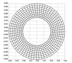
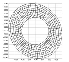
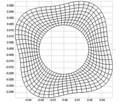
The structure is a circle with internal radius 0.02 m and external radius 0.04 m. All nodal displacements are assumed equal to zero on the internal radius. The following parameters are assumed: modulus of elasticity 6⋅108 Pa, Poisson’s ratio 0.3, density of the material 785 kg/m3.
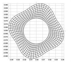
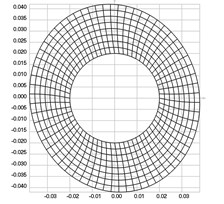
The first nine eigenmodes when 0 rad/s are presented in Fig. 1.
Fig. 1Eigenmodes when the structure does not rotate: a) the first, b) the second, …, i) the ninth eigenmode
a)
b)
c)
d)
e)
f)
g)
h)
i)
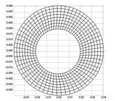
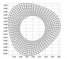
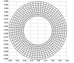
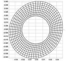
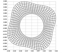
The first nine eigenmodes when rad/s are presented in Fig. 2.
From the performed investigation it was determined that centrifugal forces have effect to the eigenfrequencies and eigenmodes of the structure. But their effect to the general shape of the eigenmodes is not very great and in general the corresponding eigenmodes look similar.
Standing waves on the surface of the roller are clearly seen in some of the higher eigenmodes. They influence the quality of operation of the investigated device. Such change of thickness of the roller is clearly seen in a number of eigenmodes: in the sixth and seventh eigenmodes three places of increased thickness and three places of decreased thickness are clearly seen, in the eighth and ninth eigenmodes four places of increased thickness and four places of decreased thickness are clearly seen.
Experimental investigations indicate that because of the changes of thickness of the rollers quality of printing products becomes unacceptable. Thus as seen from the obtained numerical results excitation of eigenmodes with substantial changes of thickness of the roller must be avoided.
Fig. 2Eigenmodes when the structure rotates: a) the first, b) the second, …, i) the ninth eigenmode
a)
b)
c)
d)
e)
f)
g)
h)
i)
3. Measurement of bending vibrations of a rotating element in a folding machine
3.1. Numerical model for the analysis of bending vibrations of a rotating structure
The stiffness matrix of the plane stress problem has the form:
where is the matrix of elastic constants for the plane stress problem and is the thickness of the structure.
The loading vector of centrifugal forces for the angular velocity 1 rad/s has the form:
By solving the static problem the vector of nodal displacements is determined.
The stiffness matrix for the plate bending problem has the form:
where is modulus of elasticity, is Poisson’s ratio and:
The supplementary stiffness matrix has the form:
where:
The total stiffness matrix corresponding to rotation by the angular velocity has the form
The mass matrix has the form:
where:
3.2. Eigenmodes of bending vibrations of the rotating element of the folding machine
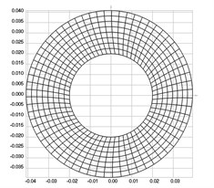
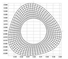
The structure is a circle with internal radius 0.02 m and external radius 0.04 m. Thickness of the structure 0.0001 m All generalized nodal displacements are assumed equal to zero on the internal radius. The following parameters are assumed: modulus of elasticity 6⋅108 Pa, Poisson’s ratio 0.3, density of the material 785 kg/m3.
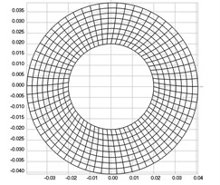
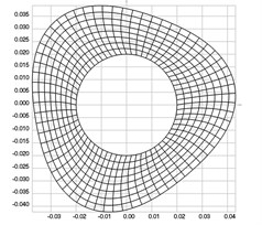
The first nine eigenmodes when 0 rad/s are presented in Fig. 3.
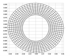
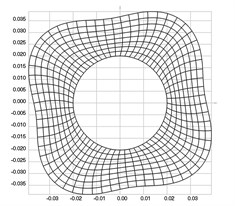
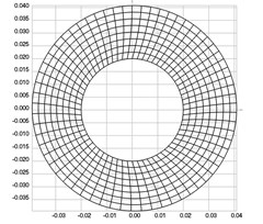
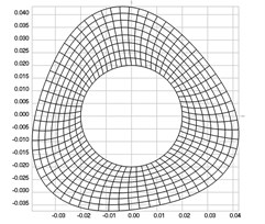
The first nine eigenmodes when rad/s are presented in Fig. 4.
From the performed investigation it was determined that centrifugal forces have effect to the eigenfrequencies and eigenmodes of the structure. But their effect to the general shape of the eigenmodes is not very great and in general the corresponding eigenmodes look similar.
Standing bending waves on the surface of the roller are clearly seen in some of the higher eigenmodes. They influence the quality of operation of the investigated device. Such bending waves of the roller are clearly seen in a number of eigenmodes: in the second and third eigenmodes one maximum and one minimum of transverse deflections on the outer diameter of the roller are seen, in the fourth and fifth eigenmodes two maximums and two minimums of transverse deflections on the outer diameter of the roller are seen, in the sixth and seventh eigenmodes three maximums and three minimums of transverse deflections on the outer diameter of the roller are seen, in the eighth and ninth eigenmodes four maximums and four minimums of transverse deflections on the outer diameter of the roller are seen.
Experimental investigations indicate that because of transverse vibrations of the rollers quality of printing products becomes unacceptable. Thus as seen from the obtained numerical results excitation of eigenmodes with substantial transverse vibrations of the roller must be avoided.
Fig. 3Eigenmodes when the structure does not rotate: a) the first, b) the second, …, i) the ninth eigenmode

a)

b)

c)

d)

e)

f)

g)

h)

i)
4. Experimental measurements of displacements of the roller of the folding machine
4.1. Experimental method and setup used for investigations
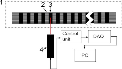
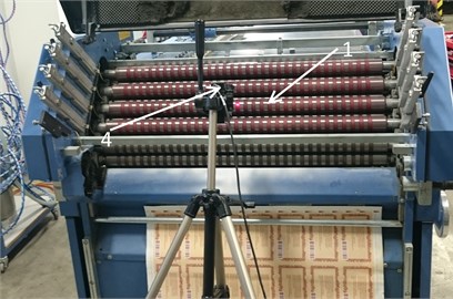
The measurements of vibrations of the roller were carried out using the displacement measurement laser head “Microtrack LTC 200-100” (see Fig. 5(a) and Fig. 5(b)). Laser light source was directed to working ring off the roller. Operation of laser head was controlled by control unit which outputted roller ring displacement in analogue signal. The analogue signal was digitalized at data acquisition unit and final data processing was carried out at personal computer.
Roller ring displacement signal from measurement head was recorded during several roller rotations. Acquired signal when was passed through low pass filter to display low frequency displacements that are caused by roller rotation. Based on the experience of operators of folding machines measurements were carried out rotating the roller at the velocity equal to 90 m/min.
Fig. 4Eigenmodes when the structure rotates: a) the first, b) the second, …, i) the ninth eigenmode

a)

b)

c)

d)

e)

f)

g)

h)

i)
Fig. 5The view of equipment and structure of measurement system: a) structure of measurement system, b) equipment used for investigations: 1 – folding roller; 2 – segment of the folding roller; 3 – working ring; 4 – laser measurement head “Microtrack LTC 200-100”; Laser head controller, data acquisition unit, personal computer with signal processing software
a)
b)
4.2. Experimental results
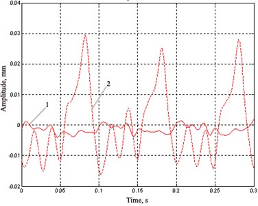
Measurements of vibrations of the roller of the folding machine were carried out before the renewal of it and after the renewal. The obtained results of measurements of vibrations of the roller of the folding machine at the velocity equal to 90 m/min are shown in Fig. 6.
Renewal of the roller of the folding machine has led to the change of the measured displacements. The displacements of the roller reduced from 30 μm before renewal to 15 μm after renewal. Such reduction positively affects the quality of folding and operation of the investigated device.
Fig. 6The results of measurements of displacements of the roller at the velocity equal to 90 m/min: 1 – after renewal; 2 – before renewal
All authors declare that all of them have made contributions to the paper.
5. Conclusions
Experimental measurements of displacements of vibrations of the roller of the folding machine have shown that renewal of the folding roller is an important factor for ensuring of the quality of printing products. The displacements after renewal are reduced up to 2 times if compared with the displacements before renewal.
From the performed investigations it was determined that centrifugal forces have effect to the eigenfrequencies and eigenmodes of the structure. But their effect to the general shape of the eigenmodes is not very great and in general the corresponding eigenmodes look similar. Thus it is necessary to avoid excitation of resonance vibrations according to some of the eigenmodes in order to ensure sufficient quality of operation of the folding device.
References
-
Huang H., Hagman A., Nygards M. Quasi static analysis of creasing and folding for three paperboards. Mechanics of Materials, Vol. 69, Issue 1, 2014, p. 11-34.
-
Barbier C., Larsson P. L., Östlund S. Numerical investigations of folding of coated papers. Composite Structures, Vol. 67, Issue 4, 2005, p. 383-394.
-
Barbier C., Larsson P. L., Östlund S. On dynamic effects at folding of coated papers. Composite Structures, Vol. 67, Issue 4, 2005, p. 395-402.
-
Barbier C., Larsson P. L., Östlund S. Experimental investigation of damage at folding of coated papers. Nordic Pulp and Paper Research Journal, Vol. 17, Issue 1, 2002, p. 34-38.
-
Sim K., Youn H. J., Oh K. D., Lee H. L., et al. Fold cracking of coated paper: the effect of pulp fiber composition and beating. Nordic Pulp and Paper Research Journal, Vol. 27, Issue 2, 2012, p. 445-450.
-
Bathe K. J. Finite Element Procedures in Engineering Analysis. Prentice-Hall, New Jersey, 1982.
-
Zienkiewicz O. C. The Finite Element Method in Engineering Science. Mir, Moscow, 1975, (in Russian).
-
Levy S., Wilkinson J. P. D. The Component Element Method in Dynamics with Application to Earthquake and Vehicle Engineering. McGraw-Hill, New York, 1976.
About this article

