Abstract
This paper considers the longitudinal coupled vibration of an elastic bearing concrete pipe pile with the saturated soil. The outer and inner saturated soil are governed by the dynamic consolidation theory originally presented by Biot. The governing equations of soil are transferred to ordinary differential equations by Laplace transform. The volumetric strain and pore pressure of soil are obtained by directly solving the coupling equations of soil without introducing potential functions. The analytical expressions of the displacements and shear stresses of the soil are then obtained. The pile response is derived on the basis of 1D elastic theory and the perfect contacts between the pile and soils. The displacement and velocity of the pile in time domain are obtained by using numerical inverse transformation. Selected numerical results are presented to portray the influence of the existences of soils, pile geometry and dynamic permeability coefficients of soils on the vibration characteristics of the pipe pile. At last, the displacement response between a pipe pile and solid pile are compared.
1. Introduction
Many theories for pile dynamics have been developed to provide useful guidelines for engineering design of pile foundations and techniques for dynamic testing of piles. Nogami and Konagai [1, 2] used an approximate time domain method to compute the response of single piles subjected to harmonic excitation, and then extended the method to the response of pile groups. Gazetas et al. [3] developed a simple method for computing the dynamic steady-state axial response of floating pile groups embedded in homogeneous and non-homogeneous soil. Wang et al. [4] proposed an analytical solution for the vertical dynamic response of an inhomogeneous viscoelastic pile. The interaction between the pile and soil were simulated by Voigt model, therefore, the real coupled vibration between the pile and surrounding soil were not considered. Novak et al. [5] developed a plane strain model assuming an elastic layer consisting of many independent infinitesimally thin horizontal layers. This model reflected the fundamental characteristics of the interaction between the pile and the surrounding soil but neglected the strain of the soil in the vertical direction. Nogami and Novak [6] developed a more rigorous model of vertically loaded end-bearing pile by assuming that the surrounding soil has no radial displacement and considering the pile-soil interaction in the vertical direction. Militano and Rajapakse [7] used Laplace transform method to deduce the frequency domain solutions for an elastic pile subjected to transient torsional and axial loadings in multi-layered elastic soil, and then obtained the time domain solutions by using a numerical Laplace inversion procedure. Hung et al. [8] studied the Seismic behavior of pile in liquefiable soil by centrifuge shaking table tests.
The above studies are based on the assumption that the soil around pile is a single phase continuum. However, the soil is generally a two-phase material consisting of a solid skeleton and pores, which are saturated with fluid. The first theory of wave propagation in saturated medium was established by Biot [9, 10]. Based on this theory, Zhou et al. [11]studied the vertical transient dynamic response of a pile embedded in a poroelastic half-space. Using the differential operator splitting and variable separation method, Yu et al. [12] investigated the time-harmonic response of an end-bearing pile in elastic saturated soil layer. Wang et al. [13] studied the longitudinal vibration of an elastic bearing pile in saturated soil layer by using potential function method.
Most of the previous studies focus on the solid pile. The concrete pipe piles are also widely used in practical engineering, such as prestressed concrete pipe piles and large-diameter cast-in-situ concrete pipe piles [14-16]. The dynamic response of a pipe pile is different from that of a solid pile because of the interaction between the pile and the inner soil. In this paper, an analytical solution for the longitudinal response of an elastic bearing concrete pipe pile in saturated soil is proposed. The frequency domain solution is obtained by directly solving the governing equations of soils without introducing potential functions. The time domain displacement and velocity responses of the pipe pile are obtained using numerical inverse transformation method. Numerical results are presented to analyze the longitudinal vibration characteristics of the concrete pipe pile.
2. Governing equations
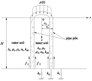
The computational model is shown in Fig. 1. A dynamic longitudinal uniform pressure is applied on the pile head. is the pile length. and are the outer and inner radii of the pile section, respectively. , , and are the complex Lame’s constants of the outer and inner soil, respectively. , , , , and are the densities, porosities and permeability coefficients of the outer and inner soil, respectively. and are the outer and inner soil resistances, respectively. It is assumed that the outer and inner soil are homogeneous and viscoelastic with frequency-independent material damping of the hysteretic type, and the soil medium is two-phase material consisting of incompressible soil grains and fluid. The pile is modeled by 1D elastic theory and has perfect contact with the outer and inner soil. The soil resistances under the soils and pile are modeled by the Winkler model, where the elastic coefficients under the outer soil, inner soil and pile are , and , respectively. The initial displacements and stresses of the pile-soil system are considered as zero.
Fig. 1Computational model
2.1. Governing equations of the outer soil
Zienkiewicz et al. [17, 18] pointed out that the convective acceleration terms of the fluid can be neglected for computation convenience. The governing equations of the outer soil undergoing axisymmetric motion, in absence of compression of the solid matrix and pore fluid, can be written as [10]:
where:
and are the radial and vertical displacements of the solid phase of the outer soil, respectively; and are the radial and vertical relative displacements between the fluid and solid phase of the outer soil, respectively; is the pore pressure of the outer soil; is the dynamic permeability of the outer soil; is the density of the pore fluid.
2.2. Governing equations of the inner soil
Similarly, the governing equations of the inner soil can be expressed as:
where:
and are the radial and vertical displacements of the solid phase of the inner soil, respectively; and are the radial and vertical relative displacements between the pore fluid and solid phase of the inner soil, respectively; is the pore pressure of the inner soil; is the dynamic permeability of the inner soil.
2.3. Wave equation of the concrete pipe pile
The motion of the concrete pipe pile is governed by the 1D elastic theory [19]:
where is the longitudinal displacement of the pile; , and are the Young’s modulus, mass density and section area of the pile, respectively.
3. Solutions for the equations
3.1. Solutions for the governing equations of the outer soil
The differentiations and yield:
Performing Laplace transform on Eqs. (12) and (13) and combining them, one obtains:
where ; is the Laplace transform of .
The solution for Eq. (14) can be easily obtained as:
where ; and are the first and second kind of modified Bessel functions of order zero, respectively.
The boundary conditions for the outer soil can be expressed as follows:
where is the normal stress of the outer soil.
It can be obtained from Eqs. (16)-(18) that:
and satisfy the following transcendental equation:
Thus can be expressed as:
, the Laplace transform of can be obtained from Eq. (12):
where ; .
Substituting Eqs. (22) and (23) into Eqs. (1)-(5), the solutions for the displacements of the outer soil can be obtained as:
where:
, , and are the Laplace transforms of , , and , respectively.
Substituting Eqs. (24) and (26) into Eq. (19) yields:
where:
The vertical displacement of the outer soil at the interface between the outer soil and the pile can be expressed as:
where .
The resistance of the outer soil, equal to the shear stress of the outer soil at the interface between the outer soil and the pile, can be obtained as:
where:
is the Laplace transform of .
3.2. Solutions for the governing equations of the inner soil
A similar solving procedure can be followed for the inner soil. The boundary conditions of the inner soil are as follows:
where is the normal stress of the inner soil.
In view of the above boundary conditions of the inner soil, the solutions for the inner soil can be derived as follows:
where:
, , , , and are the Laplace transforms of , , , , and , respectively.
The vertical displacement of the inner soil at the interface between the inner soil and the pile is expressed as:
where .
The resistance of the inner soil can be expressed as:
where:
is the Laplace transform of .
3.3. Solution for the wave equation of the pile
Performing Laplace transform on Eq. (11) and substituting Eqs. (30) and (43) into Eq. (11), one obtains:
where ; is the Laplace transform of .
The solution for Eq. (44) can be easily derived as:
where:
The displacements of the pile and the soils at the pile-soil interfaces are continuous:
Using (46) and (47), it can be obtained that:
Assuming , and , then . Given , one can obtain:
By invoking the orthogonality of eigenfunctions , and can be obtained:
where:
The boundary conditions at the top and bottom of the pile are as follows:
where is the Laplace transform of .
Substituting Eq. (45) into Eqs. (52) and (53), and can be obtained:
where:
All of the coefficients have been determined. Substituting the above coefficients into Eq. (45), the vertical displacement response of the pile can be expressed as:
The velocity response of the pile in Laplace domain can be written as:
Given , the Laplace transform can be considered as one-side Fourier transform. The frequency domain velocity admittance of the pipe pile at the pile head is defined as [4, 20]:
The time-domain displacement and velocity of the pile can be obtained by numerical inverse Fourier transform:
4. Numerical results and discussions
Numerical results are presented to verify the correctness of this solution and analyze the vibration characteristics of the pile-soil system. In the following analysis, the velocity admittance in frequency domain as well as the displacement and velocity responses in time domain of the pile are expressed as dimensionless values.
4.1. Velocity admittance in frequency domain
To verify the accuracy of the solution derived in this paper, the present solution is compared with that for an end bearing solid pile. By setting and , the elastic bearing pipe pile can be reduced to an end bearing solid pile. Fig. 2 shows the comparison of the velocity admittance between the reduced solution in this paper with the solution proposed by Yu et al. [13], where the frequency is transformed to dimensionless values by order of . It can be noted that great agreement is obtained between the two solutions.
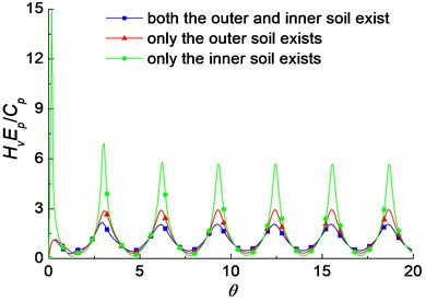
The difference between the pipe pile and solid pile is the existence of the inner soil. The outer soil and inner soil both provide resistance to the pile under dynamic loading. Fig. 3 shows the influence of the existences of the outer and inner soil on the velocity admittance of pile. It is noted that the oscillation amplitudes when only the outer soil exists are larger than those when both of the outer and inner soil exist. It shows that the existence of the inner soil has valuable influence, and the interaction between the pile and the inner soil cannot be neglected. Furthermore, the oscillation amplitudes of the velocity admittance of pile when only the inner soil exists are larger than those when only the outer soil exists, especially at the initial frequencies. It indicates that the outer soil provides more resistance than the inner soil, and the influence of the outer soil is more obvious than the inner soil.
Fig. 2Comparison of the velocity admittance between the present solution and Yu et al. (2008)
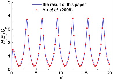
Fig. 3The influence of the existences of the outer and inner soil on the velocity admittance
The influence of the geometry of the pipe pile on the velocity admittance is shown in Fig. 4. It is noted that with the decrease of , the oscillation amplitudes increase. That means the smaller slenderness ratio, the larger oscillation amplitudes of velocity admittance. It is because the impedance of pile and radiation damping increase as the slenderness ratio increases. It is also found that the oscillation amplitudes decrease with the decrease of . That means the smaller thickness of the pile wall, the smaller oscillation amplitudes of velocity admittance. The influence of the dynamic permeability coefficients of the soils on the velocity admittance is shown in Fig. 5. It is noted that the oscillation amplitudes of the velocity admittance increase slightly with the increase of the dynamic permeability coefficients of the soils.
Fig. 4The influence of the pile geometry on the velocity admittance
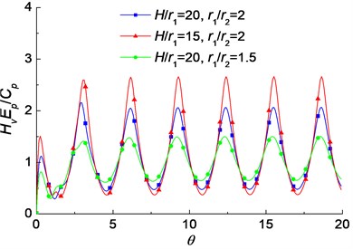
Fig. 5The influence of the dynamic permeability coefficients of the soils on the velocity admittance

4.2. Velocity response in time domain
The semisinusoidal impulse load is usually used to simulate the loading in dynamic pile testing [4, 20]. The time history of the semisinusoidal impulse is shown in Fig. 6(a), where is the amplitude of the impulse load; is the pulse width; is the dimensionless time, and . Firstly the results of the proposed solution are compared with 3D dynamic finite element analysis performed with the software ABAQUS. Eight-node, isoparametric finite elements are used to model the pipe pile and soil (Fig. 7). Infinite elements were placed on the surrounding boundary to reduce the total number of elements and provide “quiet” boundaries to prevent stress wave reflected at the far boundaries coming back to the domain of interest. The comparison of the velocity response at the pile head subjected to a semisinusoidal impulse is shown in Fig. 8. It can be seen that the proposed analytical solution are in close agreement with the FEM result.
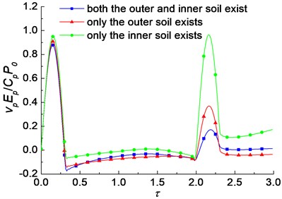
The influences of the soil existences, pile geometry and dynamic permeability coefficients of soils on the time domain velocity response at the pile head subjected to a semisinusoidal impulse are presented in Figs. 9-11. It can be found from Fig. 9 that the reflected wave signals of the pile top in the velocity curves when only the outer soil exists are larger than those when both the outer and inner soil exist, while those when only the inner soil exists are much larger than the two others. Fig. 10 indicates that the reflected wave signals increase with the decrease of and decrease with the decrease of . Fig. 11 shows that the reflected wave signals increase slightly with the increase of the dynamic permeability coefficients of the soils.
Fig. 6Transient loading considered in the analysis
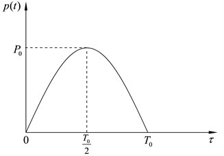
a) Semisinusoidal impulse
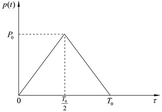
b) Triangular impulse
Fig. 7The 3D FEM mesh used for the numerical simulation of the problem
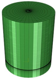
Fig. 8Comparison between the analytical solution and FEM result
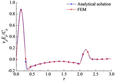
Fig. 9The influence of the existences of the outer and inner soil on the reflected wave signals
4.3. Displacement response in time domain
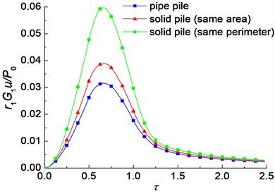
The triangular pulse is one of the commonly used types of transient loading in vibroengineering, which is shown in Fig. 6(b). Fig. 12 shows the time histories of non-dimensional displacement of the pile head of a pipe pile, a solid pile with the same area and a solid pile with the same perimeter. It is found that the displacement of a pipe pile is much smaller than that of a solid pile. The peak displacement of the pipe pile is about 23.5 % smaller than that of the solid pile with the same area, and almost half of that of the solid pile with the same perimeter. It can be concluded that use of pipe piles can efficiently decrease the vibration range of pile foundations.
Fig. 10The influence of the pile geometry on the reflected wave signals
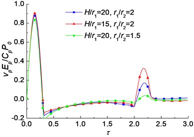
Fig. 11The influence of the dynamic permeability coefficients of the soils on the reflected wave signals
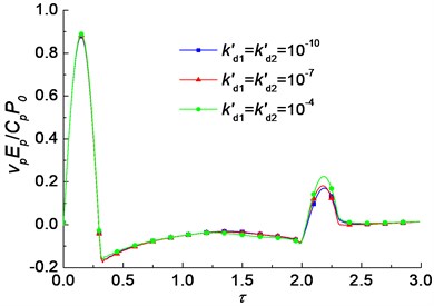
Fig. 12Time histories of non-dimensional displacement of the pile head between pipe piles and solid piles
5. Conclusions
The longitudinal coupled vibration of a concrete pipe pile with saturated soil is studied in this paper. The frequency domain solution is obtained by directly solving the governing equations of soils without introducing potential functions. The solving process and the solution are more concise, and the physical conceptions are more precise. The time domain results are obtained by using numerical inverse transformation. Some selected numerical results are given to analyze the effects of pile geometry and soil existences on the coupled vibration characteristics of the concrete pipe pile and saturated soil. The following conclusions can be obtained:
1) For a pipe pile, the inner soil also provides resistance during the vibration. The dynamic interaction between the pile and the inner soil must be considered. Nevertheless, the influence of the outer soil is much larger than that of the inner soil.
2) The oscillation amplitudes of velocity admittance and reflected wave signals increase with the decrease of slenderness ratio, while they decrease with the decrease of the outer and inner radius ratio. Furthermore, they increase with the increase of the dynamic permeability coefficients of the soils.
3) The peak displacement of the pipe pile is about 23.5 % smaller than that of the solid pile with the same area, and almost half of that of the solid pile with the same perimeter. Use of pipe piles can efficiently decrease the vibration range of pile foundations.
References
-
Nogami T., Konagai K. Time domain axial response of dynamically loaded single piles. ASCE Journal of Engineering Mechanics, Vol. 112, Issue 11, 1986, p. 1241-1252.
-
Nogami T., Konagai K. Time domain axial response of dynamically loaded pile groups. ASCE Journal of Engineering Mechanics, Vol. 113, Issue 3, 1987, p. 417-430.
-
Gazetas G., Dobry R. Dynamic pile-soil-pile interaction. Part I: analysis of axial vibration. Earthquake Engineering and Structural Dynamics, Vol. 20, Issue 2, 1991, p. 115-132.
-
Wang K. H, Wu W. B., Zhang Z. Q., Leo C. J. Vertical dynamic response of an inhomogeneous viscoelastic pile. Computers and Geotechnics, Vol. 37, Issue 4, 2010, p. 536-544.
-
Novak M., Nogami T., Aboulella F. Dynamic soil reactions for plane strain case. ASCE Journal of the Engineering Mechanics Division, Vol. 104, Issue 4, 1978, p. 953-959.
-
Nogami T., Novak M. Soil-pile interaction in vertical vibration. Earthquake Engineering and Structural Dynamics, Vol. 4, Issue 3, 1976, p. 277-293.
-
Militano G., Rajapakse R. K. N. D. Dynamic response of a pile in a multi-layered soil to transient torsional and axial loading. Geotechnique, Vol. 49, Issue 1, 1999, p. 91-109.
-
Hung W. Y., Lee C. J., Chung W. Y., Tsai C. H., Chen T., Huang C. C., Wu Y. C. Seismic behavior of pile in liquefiable soil ground by centrifuge shaking table tests. Journal of Vibroengineering, Vol. 16, Issue 6, 2014, p. 2712-2721.
-
Biot M. A. General theory of three-dimensional consolidation. Journal of Applied Physics, Vol. 12, Issue 2, 1941, p. 155-164.
-
Biot M. A. Theory of propagation of elastic waves in a fluid-saturated porous solid. I: low-frequency range. Journal of the Acoustical Society of America, Vol. 28, Issue 2, 1956, p. 168-178.
-
Zhou X. L., Wang J. H., Jiang L. F., Xu B. Transient dynamic response of pile to vertical load in saturated soil. Mechanics Research Communications, Vol. 36, Issue 5, 2009, p. 618-624.
-
Yu J., Shang S. P., Ren H., Wang H. D. Vertical dynamic response of pile in saturated soil. Engineering Mechanics, Vol. 25, Issue 10, 2008, p. 187-193, (in Chinese).
-
Wang G. M., Li Q., Wang K. H. Simplified model for vertical vibration of pile in single-layer saturated soil and its analytical solution. Chinese Journal of Rock Mechanics and Engineering, Vol. 25, Issue 2, 2006, p. 4233-4240, (in Chinese).
-
Tan Y., Lan H. L. Vibration effects attributable to driving of PHC pipe piles. Journal of Performance of Constructed Facilities, Vol. 26, Issue 5, 2011, p. 679-690.
-
Liu H. L., Chu J., Deng A. Use of large-diameter cast–in situ concrete pipe piles for embankment over soft clay. Canadian Geotechnical Journal, Vol. 46, Issue 8, 2009, p. 915-927.
-
Liu H. L., Ng C. W., Fei K. Performance of a geogrid-reinforced and pile-supported highway embankment over soft clay: case study. Journal of Geotechnical and Geoenvironmental Engineering, Vol. 133, Issue 12, 2007, p. 1483-1493.
-
Zienkiewicz O. C., Chang C. T., Bettess P. Drained, undrained, consolidating and dynamic behavior assumptions in soils. Geotechnique, Vol. 30, Issue 4, 1980, p. 385-395.
-
Zienkiewicz O. C., Shiomi T. Dynamic behavior of saturated porous media; the generalized Biot formulation and its numerical solution. International Journal for Numerical and Analytical Methods in Geomechanics, Vol. 8, Issue 1, 1984, p. 71-96.
-
Bishop R. E. D., Johnson D. C. The Mechanics of Vibration. Cambridge University Press, 1979, p. 245-247.
-
Wu W. B., Wang K. H., Zhang Z. Q., Chin J. L. Soil-pile interaction in the pile vertical vibration considering true three-dimensional wave effect of soil. International Journal for Numerical and Analytical Methods in Geomechanics, Vol. 37, Issue 17, 2013, p. 2860-2876.
About this article

This work was supported by the National Natural Science Joint High Speed Railway Key Program Foundation of China (Grant No. U1134207), the Program for New Century Excellent Talents in University (Grant No. NCET-12-0843) and the National Natural Science Foundation of China (Grant No. 51378177).
