Abstract
A sub-optimal point-to-point trajectory planning method for mobile manipulators operating in the workspace including obstacles taking into account the damping of the end-effector vibrations is presented. The proposed solution is based on extended Jacobian approach and redundancy resolution at the acceleration level. Fulfilment of the condition stopping the mobile manipulator at the destination point is guaranteed, which leads to elimination of the end-effector vibrations and significantly increases positioning accuracy. The effectiveness of the presented method is shown and compared to the classical Jacobian pseudo inverse approach. A computer example involving a mobile manipulator consisting of a nonholonomic platform (2, 0) class and SCARA-type holonomic manipulator operating in two-dimensional task space including obstacle is also presented.
1. Introduction
Mobile manipulator combining the mobility of the platform and dexterity of the manipulator can replace several stationary manipulators, moving between multiple production workstations. In such system the mobile platform allows to enlarge the workspace and the manipulator mounted on its top provides the high positioning accuracy. The main task of the mobile robot in this application is to place the end-effector in a specified point, which will enable it to perform a task on a given workstation. In this case, the trajectory of the end-effector is not significant, it is important to achieve a particular point in the workspace, avoiding possible collisions. Moreover, configuration obtained by holonomic manipulator after reaching the desired end-effector position is also significant. Achieving configuration with high manipulability measure will allow to perform a task on a given workstation without the necessity of reconfiguration. Further, such an approach results in minimizing platform movements, which are undesirable during task execution since it leads to increase in the end-effector tracking error [1, 2].
Combining the mobility of the platform with the dexterous capability of the manipulator causes that the mobile manipulator gains kinematic redundancy. The redundant degrees of freedom render it possible to accomplish complex tasks in complicated workspaces with obstacles, but redundancy also causes the solution of the mobile manipulator task to be difficult because of its ambiguity. In the literature, different approaches to solving such problems have been developed. Seraji in [3] used the augmented Jacobian matrices to obtain the mobile manipulator motion at the kinematic level. A classic solution based on the pseudo inverse of Jacobian matrix and the secondary task used for resolving redundancy of a mobile manipulator was proposed by Bayle et al. in the works [4, 5]. Fruchard et al. presented in [6] a kinematic control method based on the traverse function approach. A solution at the kinematic level to the inverse kinematics problem using optimization of performance index describing an energy lost was presented by Galicki in the work [7] to solve point-to-point problems in the workspace with obstacles. An endogenous configuration space approach was used by Tchoń and Jakubiak in [8] to solve inverse kinematic problem for a mobile manipulator.
This paper presents a sub-optimal point-to-point trajectory planning method for mobile manipulators operating in the workspace including obstacles, which takes into account the damping of the end-effector vibrations. The robot’s trajectory is planned in a manner to maximize the manipulability measure to avoid manipulator singularities. This additional condition allows to reduce redundancy of the mobile manipulator and to use the square full rank extended Jacobian matrix. Collision avoidance is accomplished by perturbing the manipulator motion close to obstacles. Opposite to similar approaches presented method incorporates nonholonomic constraints in a Pfaffian form explicitly to the control algorithm, so it does not require transformation to a driftless control system, which is not unique. Moreover, presented method guarantees the mobile platform to stop after reaching the destination point in the workspace. This feature ensures the elimination of the end-effector vibration at the end point and significantly increases positioning accuracy. To solve point-to-point problem the classic Jacobian pseudo inverse method [4] can be used, however, this approach does not ensure elimination of the end-effector vibration after reaching desired final point.
2. Problem formulation
The robotic task is to move the end-effector in the -dimensional task space from the given initial point to the final point . A mobile manipulator composed of a nonholonomic platform and holonomic manipulator with kinematic pairs of the 5th class is considered to plan a trajectory. It is described by the vector of generalized coordinates:
where is the vector of the generalized coordinates of the whole mobile manipulator, , are the vectors of the coordinates of the nonholonomic platform and the holonomic manipulator, respectively, , are the numbers of coordinates describing the nonholonomic platform and the holonomic manipulator, .
The kinematic equation of the mobile manipulator can be expressed in the form:
where is a -elemental vector, point in the workspace and function denotes -dimensional mapping describing the position and orientation of the end-effector.
At the initial moment of motion the manipulator is (by assumption) in the collision-free configuration for which the end-effector is in the initial point with zero velocity:
Introducing the end-effector tracking error defined as:
the task of the mobile manipulator can be presented in general form as follows:
Using the mobile manipulators involves additional kinematic (in general) nonholonomic constraints reducing their local mobility. They can be described in the Pfaffian form as:
where is Pfaffian full rank matrix and is the number of nonholonomic constraints.
Conditions resulting from the constraints connected with the obstacles existing in the workspace for manipulator configuration can be written as a set of inequalities:
where is a scalar function which describes collision-free conditions of the manipulator with the obstacles and stands for a total number of collision avoidance conditions.
The dependencies Eqs. (3)-(8) formulate the robotic task, whose solution is the trajectory of the mobile manipulator that satisfies constraints Eqs. (7)-(8) in each time instant.
3. Trajectory generation at the acceleration level
To solve the problem defined in the above section, two methods of trajectory planning are presented. The first one is classic Jacobian pseudo inverse approach [9] with secondary objective functions used to avoid collisions with obstacles. The second one is a solution taking into account the transversality conditions and extended Jacobian proposed by the authors, which allows to eliminate the drawback of the classic approach.
3.1. Classical Jacobian pseudo inverse method
The solution of the point-to-point problem Eq. (3)-(7) using Jacobian pseudo inverse is similar to the method used to solve the problem of end-effector trajectory tracking presented in [2]. According to this approach the end-effector tracking error Eq. (4) has to be extended as follows:
where ; denotes null matrix.
As stated in [2] may be interpreted as error between a current and final configuration, mappings ,…, are responsible for reaching the given final point and the mappings ,…, are responsible for the fulfilment of constraints Eq. (7).
For simplicity of further calculations the following notation is introduced:
where , and .
In order to solve the trajectory planning problem, the following system of differential equations is proposed (see works [10] and [11] for stationary manipulators):
where , are diagonal matrices with positive coefficients, ensuring the stability of the first equation, and is diagonal matrix with positive coefficients ensuring the stability of the second equation.
The dependence Eq. (11) is a system of homogeneous differential equations with constant coefficients. Proposed form of the equations ensures that their solution is asymptotically stable for positive coefficients , and , which implies fulfilment of the conditions Eq. (5)-(6). Additionally, if nonholonomic conditions are fulfilled at the initial moment of the motion (e.g. if initial velocity is equal to zero), they are also fulfilled during the entire movement.
After simple calculations Eq. (11) can be transformed into the following form:
where is the pseudo inverse of matrix , and .
The dependence Eq. (13) allows to determine the trajectory from the initial point to the final point satisfying nonholonomic constraints Eq. (7). In order to take into account the collision avoidance conditions Eq. (8) the secondary objective function approach [12] is used. For this purpose vector representing perturbations of mobile manipulator accelerations in neighbourhood of obstacles, pushing the robot away from the obstacles, is introduced:
where is assumed to be non-negative continuous scalar penalty function, which equals zero outside the neighbourhood of the th obstacle, increasing towards the obstacle [13].
Finally, dependence Eq. (12) is generalised by adding an additional component to satisfy secondary objective function Eq. (13) as follows:
where is the projection matrix of the vector in the null space of , which does not allow to violate the primary objective Eq. (12), denotes identity matrix.
The method described above allows to find trajectory of mobile manipulator performing the task Eqs. (3)-(6), fulfilling nonholonomic constraints Eq. (7) and collision avoidance conditions Eq. (8), however, it has a significant drawback. Combination of the mobile platform with the manipulator causes that even relatively simple constructions have high number degrees of freedom and typically is redundant for many tasks. The existence of redundant degrees of freedom makes it possible to perform the task in infinitely different ways. The solution presented above does not impose any additional conditions on the motion of the mobile manipulator, so after reaching the final point the robot will not stop. These undesirable motions may cause unnecessary energy consumption, lead to vibrations of the end-effector and consequently the desired point can not be achieved with appropriate precision (see Section 4). As a result, realisation of the next task, which would be carried out by mobile manipulator after reaching point will be difficult.
3.2. Extended Jacobian approach
As mentioned above, using the classic method based on Jacobian pseudo inverse Eq. (14) can lead to undesirable end-effector vibrations after reaching the point . The reason of this drawback is the movement of the mobile manipulator after attaining by the end-effector its desired location. In the case of point-to-point problem the platform should be used to achieve the position in which the point is in the range of the end-effector and after reaching this point the mobile manipulator should stop. As a consequence an additional constraint imposed on mobile manipulator velocity should be considered in the following form:
Fulfilment of constraint Eq. (15) will reduce vibrations of the end-effector and significantly increase the positioning accuracy. This additional constraint can be introduced as a new secondary objective in a similar manner as in [2]. However, in such case there are several secondary objectives which can be conflicting and simultaneous optimisation of them cannot be possible. Additionally, the found solution depends on the choice of arbitrarly given weights and first of all, there is no guarantee of the fulfilment of secondary objectives. Because of these reasons using secondary objective to take into account condition Eq. (15) does not ensure its fulfilment, so there is no guarantee that the mobile manipulator will stop after reaching the point and vibrations of the end-effector will not be reduced. Therefore, in this section another trajectory planning method, free of these disadvantages, using extended Jacobian is presented.
To extend Jacobian matrix additional condition has to be taken to reduce redundancy of mobile manipulator. A number of different indices could be taken into consideration, but it seems reasonable to use of the redundant degrees of freedom to avoid manipulator singular configurations. For this purpose the instantaneous performance index is introduced as follows:
Minimisation of performance index Eq. (16) leads to maximisation of mobile manipulator manipulability measure [14]. Consequently, after reaching the desired point the manipulator will attain high dexterity, which will allow to carry out the next task without the necessity of reconfiguration. Finally, the original robotic task formulated by dependencies Eqs. (3)-(8) is complemented by the additional condition Eq. (15) and minimisation of performance index Eq. (16). At the beginning, the solution of the point-to-point problem ensuring zero velocity at the end of the movement and maximisation of manipulability measure without collision avoidance conditions is presented.
Necessary condition to obtain the minimum of performance index is that the differential of at equals zero:
where is -dimensional vector and is -dimensional vector, the differential of generalised coordinates. Based on the solution presented in [15, 16] necessary condition Eq. (17) taking into account Eqs. (5)-(7) takes the form called transversality conditions [17]:
where is square matrix constructed from linear independent columns of , is matrix obtained by excluding from and denotes identity matrix.
Using a similar approach as in previous section, end-effector tracking error Eq. (4) may be extended to the following form:
As in the previous section, the mapping may be interpreted as a measure of error between a current configuration and non-singular, final configuration in desired point . The first components of are responsible for reaching the given final point , the next dependencies are responsible for minimisation of the performance index Eq. (16) and the -last components are responsible for the fulfilment of constraints Eq. (7). Similarly as in Jacobian pseudo inverse approach to find the trajectory of the mobile manipulator the following dependencies are proposed:
where and are diagonal matrices with positive coefficients, ensuring the stability of the first equation, is diagonal matrix with positive coefficients ensuring the stability of the second equation,
Proposed form of the system of homogeneous differential equations Eq. (20) ensures that their solution is asymptotically stable for positive coefficients , and . The property of asymptotic stability implies fulfilment of the dependencies Eqs. (5)-(7), moreover if initial configuration is non-singular, the robotic motion is free of singularities during the movement to the final point .
Finally, the trajectory of the mobile manipulator can be determined by simple transformations from the dependence Eq. (20) as:
where: , , .
Introducing the additional criteria Eq. (16) and consequently using the transversality conditions Eq. (18) results in the extended Jacobian being the square matrix. Moreover, using the criteria Eq. (16) leads to avoiding singular configurations, so extended Jacobian is also full rank matrix and therefore the use of Jacobian pseudo inverse is not needed. The solution of differential equations is asymptotically stable, so:
Moreover, because the extended Jacobian is the square full rank matrix and consequently condition Eq. (15) is fulfilled.
Mobile manipulator trajectory obtained from differential Eq. (21) ensures execution of the task Eqs. (5)-(6), fulfils the nonholonomic constraints Eq. (7), minimises performance index Eq. (16) and guarantees fulfilment of constraint Eq. (15). For collision-free trajectory planning similar approach as in previous section may be used. To push the robot away from the obstacles neighbourhood mobile manipulator accelerations are perturbed as follows:
where is the pseudoinverse of matrix , matrix is chosen to fulfil nonholonomic constraints Eq. (7) and is a vector of accelerations perturbations Eq. (13).
Finally, trajectory generator Eq. (23) allows to find non-singular collision-free trajectory from the initial point to the final point ensuring zero velocity at the end of the movement. Such solution leads to eliminating vibrations of the end-effector in the final point and significantly increases positioning accuracy and therefore removes the main drawback of the method presented in Section 3.1. Moreover, maximisation of the manipulability measure results in high dexterity of the manipulator after task accomplishment and allows to perform the next task without the necessity of reconfiguration.
4. Numerical example
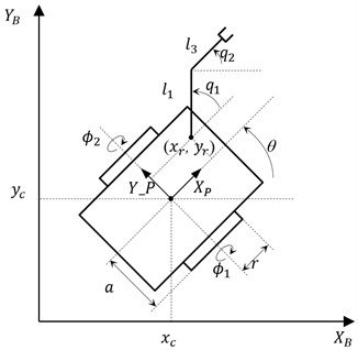
In the numerical example, a mobile manipulator consisting of a nonholonomic platform of (2, 0) class and a SCARA type holonomic manipulator, shown in Fig. 1, working in a two-dimensional task space is considered. The mobile robot is described by the vector of generalised coordinates:
where is the platform centre location, is the platform orientation, , are angles of driving wheels and , are joints’ angles of the holonomic manipulator.
The mobile manipulator works in plane of the base coordinate system, its kinematic equation is given as:
where and are the lengths of the manipulator arms.
Fig. 1Kinematic scheme of the mobile manipulator
The motion of the platform is subject to one holonomic and two nonholonomic constraints, so constraints Eq. (7) in this case take the following form:
where is the radius of driving wheels, and is half-distance between the wheels.
The kinematic parameters of the mobile manipulator are given as (all physical values are expressed in the SI system): 1.0, 1.0, 0.3, 0.075, 0.75, The task of the manipulator is to move the end-effector from the initial point to the final point . In the workspace there is one obstacle represented by a circle with radius 0.5 and the centre point placed at . The obstacle is surrounded by a safety zone with radius 0.4. The simulation time is set to 35 seconds.
In order to compare trajectory generators introduced in Section 3, two cases of performing this task are considered. In the first one the trajectory of the mobile robot is determined using the method based on Jacobian pseudo inverse Eq. (14), in the second one extended Jacobian approach Eq. (23) is used. In both cases the values of gain coefficients are assumed as: , , . In the initial moment of the motion the mobile manipulator does not move, the platform centre is in position 0, , its orientation amounts and configuration of the holonomic manipulator is taken as , , so the end-effector is located in the initial point . In both cases two simulations are carried out: in the first one collisions avoidance conditions are not considered in the second one the obstacle is taken into account.
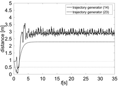
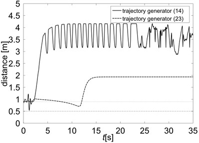
Fig. 2 presents distances between mobile manipulator and the centre of the obstacle. The dashed gray line represents the radius of the obstacle, the dotted gray line represents the radius of the obstacle neighbourhood. On the left of Fig. 2 the results of simulations without collision avoidance conditions are presented. In both cases (trajectory generators Eq. (14) and Eq. (23)) it can be seen that the mobile manipulator potentially collides with the obstacle in the first stage of the motion. The right side of Fig. 2 shows the distances when the collision avoidance conditions are taken into account. As it is seen, in both cases, the mobile manipulator penetrates the safety zone of the obstacle, but does not collide with it. In the case of trajectory generator based on Jacobian pseudo inverse (solid line), the robot moves faster, but its distance from the obstacle changes throughout the simulation, that means it does not stop after reaching the final point. In the case of trajectory generator using extended Jacobian (dashed line) the robot moves more slowly, but after time greater than 15 [s] its distance from the obstacle remains constant.
Fig. 2Distances between the mobile manipulator and the centre of the obstacle: a) simulation without collisions avoidance conditions, b) collision-free motion
a)
b)
Fig. 3 presents comparison of the end-effector tracking errors for trajectory generators Eq. (14) and Eq. (23). For clarity of presentation the first stage of the task execution is omitted and the tracking errors are depicted only for the stage when the end-effector is near the final point . As can be seen use of the generator Eq. (14) leads to undesirable end-effector vibrations, which affect the positioning error of the order of 10-3 [m]. Application of generator Eq. (23) using extended Jacobian results in positioning error monotonically to converge to zero and consequently leads to elimination of the end-effector vibrations and significantly increase positioning accuracy.
Fig. 3Norm of end-effector tracking error for trajectory generators Eq. (14) and Eq. (23)
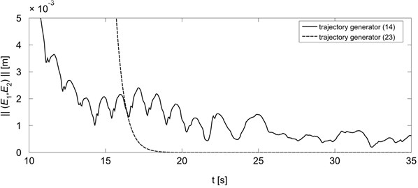
Fig. 4 presents the norm of the mobile manipulator velocities (platform wheels and holonomic manipulator joints) during the execution of the task for both generators. As can be seen, in the case of use of trajectory generator based on Jacobian pseudo inverse the mobile manipulator does not stop after reaching the final point (15 [s]). The norm of robot velocities remains at approximately constant level (there are slight changes, barely visible at this scale) which affects end-effector vibrations show in Fig. 3. In the case of trajectory generator Eq. (23) mobile manipulator stops after reaching point (18 [s]), which leads to elimination of end-effector vibration and results in increase in positioning accuracy.
Fig. 4Norm of mobile manipulator velocities for trajectory generators Eq. (14) and Eq. (23)
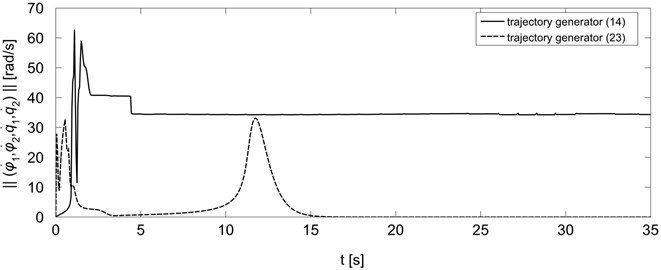
Fig. 5Manipulability measure for trajectory generators Eq. (14) and Eq. (23)
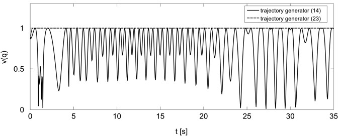
An additional advantage of using extended Jacobian approach is increase of holonomic manipulator dexterity. Changes of manipulability measure are presented in Fig. 5. As can be seen, the manipulability measure obtained for generator Eq. (14) has a large amplitude changes and despite the large initial value being close to zero during the motion. In the case of generator Eq. (23) manipulability measure quickly reaches a maximum value and remains constant until the end of the task, so after reaching the final point manipulator attains high dexterity and it can perform the next task without necessity of reconfiguration.
Results of numerical simulations presented above confirm the correctness of the proposed method of the end-effector vibration elimination introduced in Section 3.2. All simulations have been carried out in a Matlab 7 environment running on an ordinary personal computer with Intel Core i7 processor. The sampling time in each simulation has been equal to 0.01 s, computational times have been comparable to the resulting execution times. The obtained results indicate that the method can be used to real-time trajectory planning.
5. Conclusions
In the paper a point-to-point trajectory planning method for a mobile manipulator operating in the workspace including obstacles is presented. Unlike most of the existing research, this work takes into account the end-effector vibrations arising at the desired final point, which significantly decreases positioning accuracy. The problem is solved by using extended Jacobian approach at the acceleration level. The collision avoidance is accomplished by local perturbing of the mobile manipulator motion in the neighbourhoods of the obstacles. The proposed method incorporates nonholonomic constraints in a Pfaffian form explicitly to the control algorithm, which allow to avoid constraints transformation to a driftless control system. The solution ensures that mobile manipulator stops after reaching desired final point and achieves a high manipulability measure at the end of the motion. As shown by the numerical simulations this approach leads to elimination of the end-effector vibrations and significantly increases positioning accuracy. Moreover, at the final point the mobile manipulator obtains configuration ensuring high dexterity which allows the execution of a next task without the necessity of reconfiguration. The effectiveness of the proposed solution is confirmed by the results of computer simulations.
References
-
Galicki M. Two-stage constraint control of mobile manipulators. Mechanism and Machine Theory, Vol. 54, 2012, p. 18-40.
-
Pajak G. End-effector vibrations reduction in trajectory tracking for mobile manipulator. Journal of Vibroengineering, Vol. 17, Issue 1, 2015, p. 101-111.
-
Seraji H. A unified approach to motion control of mobile manipulators. International Journal of Robotics Research, Vol. 17, Issue 2, 1998, p. 107-118.
-
Bayle B., Fourquet J. Y., Renaud M. A coordination strategy for mobile manipulation. Proceedings of 6th Internationl Conference Intelligent Autonomous Systems (IAS-6), Venice, Italy, 2000, p. 981-988.
-
Bayle B., Fourquet J. Y., Renaud M. Manipulability of wheeled mobile manipulation: application to motion generation. International Journal of Robotics Research, Vol. 22, Issues 7-8, 2003, p. 565-581.
-
Fruchard M., Morin P., Samson C. A framework for the control of nonholonomic mobile manipulators. International Journal of Robotics Research, Vol. 25, Issue 8, 2006, p. 745-780.
-
Galicki M. Inverse kinematics solution to mobile manipulators. International Journal of Robotics Research, Vol. 22, Issue 12, 2003, p. 1041-1064.
-
Tchoń K., Jakubiak J. Endogenous configuration space approach to mobile manipulators: a derivation and performance assessment of Jacobian inverse kinematics algorithms. International Journal of Control, Vol. 76, 2003, p. 1387-1419.
-
Liegeois A. Automatic supervisory control of the configuration and behavior of multibody mechanisms. IEEE Transactions on SMC, Vol. 7, Issue 12, 1977, p. 868-871.
-
Pajak I., Galicki M. The planning of suboptimal collision-free robotic motions. Proceedings of 1st International Workshop Robot Motion and Control, 1999, p. 229-243.
-
Pajak G., Galicki M. Collision-free trajectory planning of the redundant manipulators. Proceedings of 6th International Conference on Methods and Models in Automation and Robotics, 2000, Vol. 2, p. 605-610.
-
Siciliano B., Sciavicco L., Villani L., Oriolo G. Robotics. Modeling, Planning and Control. Springer, 2009.
-
Morecki A. Fundamentals of Robotics. WNT, 1999, (in Polish).
-
Yoshikawa T. Manipulability of robotic mechanisms. International Journal of Robotics Research, Vol. 4, Issue 2, 1985, p. 3-9.
-
Pająk G., Motion planning for mobile surgery assistant. Acta of Bioengineering and Biomechanics, Vol. 16, Issue 2, 2014, p. 11-20.
-
Pająk G., Sub-optimal trajectory planning for mobile manipulators. Robotica, 2014, p. 1-20.
-
Galicki M. Optimal planning of a collision-free trajectory of redundant manipulators. International Journal of Robotics Research, Vol. 11, Issue 6, 1992, p. 549-559.
About this article

