Abstract
Horizontally vibrating characteristics of a tubular pile in saturated soil layer are studied in this paper. Governing equations of the pile is deduced based on the popular Timoshenko theory. Analytical solutions of the pile response are derived based on the continuous boundary conditions in the pile-soil interface. Accordingly, analytical expressions of the pile impedances are obtained. Based on it, a comparison with the Euler-Bernoulli Model is performed to verify this solution. Parametric analyses are carried out to study horizontal responses of the tubular pile.
1. Introduction
Since mono-piled ocean towers are widely used to supported superstructures like wind turbine, offshore platforms, dynamic behavior of these laterally loaded piles is an area of extensive research. These piles designed for resisting lateral loadings are typically analyzed following different pile-soil interaction models [1-3], in which the Euler-Bernoulli theory is adopted to model the horizontally vibrating piles and the soil is simulated through the Winkler Foundation Model, infinitesimally thin layer or 3D continuum media, respectively.
The widely used Euler-Bernoulli Model, adopted in the conventional modelling of piles, is applicable for beams with / > 10 i.e. slenderness ratio > 10 [4]. However, offshore structures like wind turbine generators always adopt very large diameter tubular piles with very low aspect ratio as foundations [5]. For these monopiles, the application of Euler-Bernoulli theory may not be appropriate since the shear deformation is significant compared with the bending deflection during horizontal vibration. Meanwhile, the Euler-Bernoulli Model fails to consider the shear deformation, which can be reflected by the Timoshenko theory [6]. Although piles are mostly simulated by Euler-Bernoulli theory, a few studies are reported to apply the Timoshenko Model in monopiles [7, 8].
This paper shows applications of the Timoshenko theory in analyses of tubular piles with large diameter, to extend the existing analytical approach for horizontally loaded pipe piles [4, 9, 10]. It offers a generalized analytical approach for large diameter pipe piles considering shear deformations and inertial effects in the process of pile horizonal vibrating, which has been rarely investigated as the authors know. Analytical expressions for the pile lateral displacement, rotation angel, bending moment and shearing force are derived based on the continuity condition of the pile-to-soil system. A few numerical examples are performed to compare the difference between Euler-Bernoulli theory and Timoshenko theory in modelling the large diameter pipe pile, and reveal horizontal dynamic characteristics of the pile.
2. Problem definition
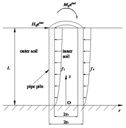
A single large diameter tubular pile with pile length , radius and modelled by Timoshenko model and surrounded by two-phase saturated soil is detailed in Fig. 1(a). A horizontal force and a moment are applied on the tubular pile head ( is the circular frequency). and are the lateral resisting forces coming from the outer soil and inner soil, respectively. A cylindrical coordinate system shown in Fig. 1(a) is chosen for the analytical analyses of the pile-to-soil system.
The soil medium is supposed to behave as a viscoelastic, isotropic and homogeneous saturated soil based on the Biot’s theory [11]. The pipe pile assumed as a Timoshenko beam with flexibility . There is no slippage or separation between the tubular pile and the two-phase soil (including inner and outer soil). The normal and shear stress atop the soil layer and displacements at the bottom of the two-phase medium are assumed to be zero.
Fig. 1Computational model
a) Schema of the pile-soil system
b) Computing element
3. Differential equations of the pipe pile
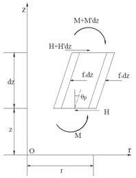
The internal forces (shearing force , bending moment ) and deformations (horizontal displacement , rotation angle ) of a differential element for the tubular pile based on Timoshenko model are presented in Fig. 1(b). Apostrophe at the top right corner denotes differentiation with respect to . Taking inertia moment and shearing deformation into account, using the equilibrium equations of the horizontal dynamic load and bending moment acting to differential element of the pipe pile and neglecting the second order terms give:
where is the mass density of the tubular pile.
According to Timoshenko theory, the internal forces can be written as:
where , and are, respectively, cross sectional area, shear modulus and shearing factor.
Substitutions of Eqs. (8), (9) into Eqs. (6), (7) gives:
Consequently, differential equations of the pipe pile based on Timoshenko model can be obtained from Eqs. (10) and (11) as:
4. Determination of the tubular pile responses
4.1. Review of soil analysis
The dynamic horizontal resistance of the saturated soil to lateral pile motion can be obtained through the following expression [9, 12]:
where is the soil reaction factor, is an undetermined coefficient, is the soil mode and subscript denotes the th mode ( 1, 2, 3, …).
The th soil mode is expressed through a simple frequency independent function:
where .
Detailed, the outer and inner soil reaction factor , are expressed through the modified Bessel functions, respectively:
where , , and are determined coefficients.
Accordingly:
where is an undetermined constant.
4.2. Analytical Solution for the tubular pile
Eqs. (3) and (4) are coupled with each other in views of and , decomposed as:
where , .
Substituting Eqs. (10) into Eq. (11) yields:
Eq. (13) is an ordinary differential equation with inhomogeneity, whose solution can be derived as:
and - are coefficients.
According to the perfect contact boundary condition of the pile-to-soil system, lateral displacements at the pile-soil interfaces are continuous:
Accordingly:
Multiplying on both sides of Eq. (15) to integrate on the range, [0, ], yields:
Substituting Eq. (18) into Eq. (17) results in:
Now Eq. (14) can be re-written as:
Using the same solving procedure, the solution of (12) can be obtained as:
Therefore, (bending moment) and (shearing force) of the tubular pile can be obtained by:
Assuming that horizontal displacement , rotation angle , bending moment and shearing force at pile head are , , and , respectively. Therefore, undetermined coefficients - can be determined by the method of initial parameter. As for the limited paper space, the detailed determination process of - are excluded here.
Based on the definition method for impedances proposed by Novak [13], the dimensionless horizontal dynamic impedance , rocking dynamic impedance and horizontal-rocking dynamic impedance can be expressed as follows, respectively:
5. Validation and analysis
A few numerical examples are selected to make comparisons between the results of the Euler-Bernoulli theory and the Timoshenko theory, and to analyze the horizontal dynamic responses of the tubular pile based on the Timoshenko theory. Unless otherwise specified, details of parameters used in this study are listed as follows: 10 m; 0.5 m; 0.3 m; 25 GPa; 2500 kg/m3; 2200 kg/m3; 1000 kg/m3; 0.99; 1000 MPa; 0.3, 10-5m/s. Variations of the three stiffness factors (, , ) and damping factors (, , ) with frequency are similar. Accordingly, and are taken as examples for the numerical analysis.
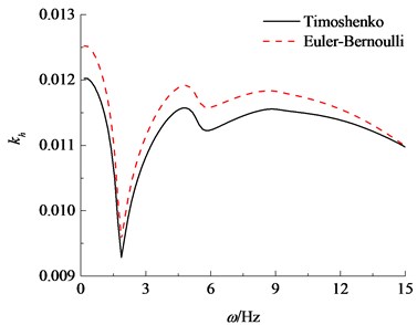
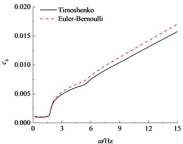
Figs. 2 compares the dynamic stiffness and damping factors (, ) calculated by the Timoshenko model with those by the Euler-Bernoulli model. It is observed that the variation tendency of the stiffness and damping factors calculated by the both models are uniform, which represents the validity of the proposed solution. While the calculation results obtained by the Timoshenko model are significantly less than those obtained by the Euler-Bernoulli model. This is due to the fact that effects of shear deformation and inertia are taken into account, in addition to the bending deflection of the pipe pile in the Timoshenko model. The result calculated by the Euler-Bernoulli model is bigger than normal. This is bound to bring about potential safety hazard, especially for the large diameter pipe pile. Accordingly, it is reasonable to simulate the large diameter pipe pile by Timoshenko model.
Fig. 2Comparisons of horizontal impedance between the Euler-Bernoulli and Timoshenko theories
a) Real component
b) Imaginary component
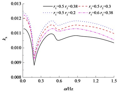
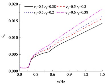
Fig. 3 takes the horizontal dynamic stiffness factor and damping factor as examples to illustrate influences of the radius i.e. and on the complex impedances of the tubular pile modelled by the Timoshenko model. It is observed that horizontal dynamic stiffness and damping components tends to increase with the decrease of the inner radius and the increase of the outer radius . Notice that cross section area of the tubular pile for the case of 0.5 and 0.2 is equal to the case of 0.6 and 0.38, approximately. Comparison of the two cases finds that stiffness component of the tubular pile with 0.5 and 0.2 is larger than that with 0.6 and 0.38, while the damping factor is reverse. This implies that, for cases of tubular piles with approximately equal cross section area, stiffness component of the tubular pile with comparatively larger wall thickness is greater, while the damping factor of a pipe pile with larger mean radius (/2 + /2) is greater.
Fig. 3Variation of horizontal impedance with inner and outer pile radius based on the Timoshenko theory
a) Real component
b) Imaginary component
6. Conclusions
Interaction between the saturated soil and a large diameter tubular pile in horizontal vibration is theoretically examined. The analytical solution is brought to a form which makes it possible to predict the dynamic stiffness and damping for the large diameter pipe pile based on the Timoshenko model. Comparisons between the Timoshenko model and the Euler-Bernoulli model are presented to illustrate the influence of shear deformation and inertial effect on the dynamic responses.
References
-
Zhang C., Yu J., Huang M. Winkler load-transfer analysis for laterally loaded piles. Canadian Geotechnical Journal, Vol. 53, Issue 7, 2016, p. 1110-1124.
-
Shadlou M., Bhattacharya S. Dynamic stiffness of pile in a layered elastic continuum. Géotechnique, Vol. 64, Issue 4, 2014, p. 303-319.
-
Hu A. F., Fu P., Xia C. Q., et al. Lateral dynamic response of a partially embedded pile subjected to combined loads in saturated soil. Marine Georesources and Geotechnology, Vol. 35, Issue 6, 2017, p. 788-798.
-
Gupta B. K., Basu D. Applicability of Timoshenko, Euler-Bernoulli, and Rigid beam theories in analysis of laterally loaded monopiles and piles. Géotechnique, Vol. 68, Issue 9, 2018, p. 772-785.
-
Shadlou M., Bhattacharya S. Dynamic stiffness of monopiles supporting offshore wind turbine generators. Soil Dynamics and Earthquake Engineering, Vol. 88, 2016, p. 15-32.
-
Shames I. H. Energy and Finite Element Methods in Structural Mechanics. CRC Press, 1985.
-
Byrne B. W., Mcadam R., Burd et al. H. J. New design methods for large diameter piles under lateral loading for offshore wind applications. 3rd International Symposium on Frontiers in Offshore Geotechnics, Oslo, Norway, 2015.
-
Ankit A., Datta N., Kannamwar A. N. Free transverse vibration of mono-piled ocean tower. Ocean Engineering, Vol. 116, 2016, p. 117-128.
-
Zheng C., Liu H., Ding X. Lateral dynamic response of a pipe pile in saturated soil layer. International Journal for Numerical and Analytical Methods in Geomechanics, Vol. 40, Issue 2, 2016, p. 159-184.
-
Datta, Kannamwar A. N. Free transverse vibration of mono-piled ocean tower. Ocean Engineering, Vol. 116, 2016, p. 117-128.
-
Biot M. A. Theory of propagation of elastic waves in a fluid-saturated porous solid. I. Low-frequency range. The Journal of the acoustical Society of America, Vol. 28, Issue 2, 1956, p. 168-178.
-
Ding X., Luan L., Zheng C., et al. Influence of the second-order effect of axial load on lateral dynamic response of a pipe pile in saturated soil layer. Soil Dynamics and Earthquake Engineering, Vol. 103, 2017, p. 86-94.
-
Novak M. Dynamic stiffness and damping of piles. Canadian Geotechnical Journal, Vol. 11, Issue 4, 1974, p. 574-598.
