Abstract
In this paper, the impact resistance of a fastening belt of the underwater vehicle life raft is studied, which is based on Germany BV043/85 standard. Performing finite element simulation for the fastening belt with ANSYS Workbench software. Calculating the deformation and stress distribution of the fastening belt under impact loading. This method can accurately reflect the impact resistance of the fastening belt. Comparing with the design requirements can verify the reliability of the fastening belt.
1. Introduction
Ships use inflatable life raft as a life-saving equipment in most of time. To apply inflatable life raft for underwater vehicles, the research group designed a new inflatable life raft release device. When the underwater vehicle encounters an accident during the voyage, people who need to escape from the underwater vehicle can release the inflatable life raft under water. It can form a small rescue platform on the water for people. It can greatly improve the probability of survival and rescue. The whole set of life raft equipment is composed of an automatic inflating life raft, two pressure-bearing hemispheric shells, a fastening belt, an ejection mechanism and an installation platform. The inflatable life raft is placed inside two pressure-bearing hemispheric shells, and the fastening belt fastens the two hemispheric shells to the mounting bracket. After releasing the fastening belt, the spherical shell goes upon the water because of buoyancy. When near the sea level, a pressure sensor makes the raft to be inflated automatically. In the whole device, whether the fastening belt can fix the pressure spherical shell on the mounting bracket effectively is the precondition for the whole device to work reliably. The fastening belt will be subjected to a variety of impact forces under water. The impact force from below will cause the maximum deformation of the fastening belt. This study can provide a support for the optimization design of the fastening belt.
2. Stress analysis of fastening belt
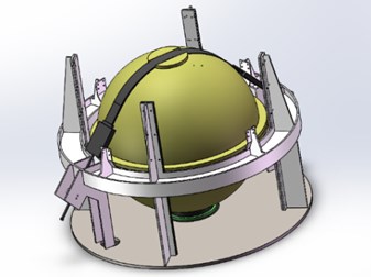
Life raft ball is fixed on the installation platform before releasing. There are four guide supports around the installation platform, which can limit the horizontal displacement of the life raft ball. The fastening belt shall make the vertical displacement less than the depth of the groove at the bottom of the installation platform. The two ends of the fastening belt are fixed by an adjustable screw device. The middle part of the fastening belt fixes on the gap upon the upper hemisphere. The fastening belt composition by three parts, the middle part is a steel wire belt composed of multiple steel wire ropes. Steel wire contacts with the surface of the sphere directly. The end of the wire rope is rubber blocks. Rubber block can provide downward displacement and pressure through the pre-tightening force. The end of the rubber block is connecting rods for connecting the rubber block and mounting platform. Fig. 1 is a schematic diagram of the overall installation of life raft.
Life raft works in the sea 300 meters below. The hydraulic pressure will cause deformation of life raft ball. The hydraulic pressure can be calculated by pressure formula . The density of water is 1.03 g/cm3.The acceleration of gravity is 9.8 N/kg. The hydraulic pressure can be calculated as 3.028 MPa. The sphere is affected by buoyancy, because it is hollow. The buoyancy force can calculated by (9.8 N/kg). The buoyancy is 5738.15 N. The magnitude of gravity can be determined by the formula . The magnitude of gravity is 1822.7 N. It is necessary to apply a pre-tightening force on the fastening belt during installation to make the rubber block deformed. So that the fastening belt can generate a downward displacement and pressure. The ball will be firmly pressed on the installation platform by fastening belt.
The life raft upward movement distance will increase when under the impact. if upward movement distance is longer than groove height at the bottom (15 mm). The whole life raft ball will not be able to maintain a balance on the installation platform. It will affect the normal work of the life raft. To solve this problem, it’s necessary to assess the impact resistance of the fastening belt. And the impact load shall be applied to the life raft in the calculation process. The specific value and form are referred by BV043/85 standard.
Fig. 1Schematic diagram of the overall installation of life raft
3. Fastening belt modeling
In this paper, the transient structural analysis system is adopted. Based on the static structural analysis, this module can load the impact force or acceleration to solve the stress distribution of the model in a very short time [1]. First, using SolidWorks software to design the 3D model, and import the model into ANSYS Workbench through the seamless data interface between SolidWorks and ANSYS Workbench [2].
Fig. 2Grid partitioning in the ANSYS Workbench
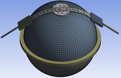
The life raft ball is made of S-type glass fiber. Young’s modulus is 8.5×10⁴MPa. Poisson’s ratio is 0.22. Density is 2.45 g/cm3.The raft ball is meshed by MultiZone. The middle of the fastening belt constituted with wire belt. The wire belt is made of 316L Stainless steel. Young’s modulus is 2.06×10⁵MPa. Poisson’s ratio is 0.28. Density is 7.98 g/cm3.Wire belt is meshed by Hex-Dominant [3]. The rubber block on both sides of the fastening belt is made of butadiene rubber. Young’s modulus is 6.1 MPa. Poisson’s ratio is 0.49. Density is 10 g/cm3.Rubber block is meshed by Sweep. Element size is set to 20 mm. The connecting rod is treated as same as the wire belt [4]. Fig. 2 shows the grid partitioning.
After processing, the whole life raft model has 9305 elements and 23452 nodes.
4. Analysis of impact resistance of fastening belt
4.1. Input of impact analysis
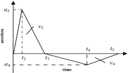
In this paper, the BV043/85 standard issued by Germany in 1985 was adopted as the input value of impact [5]. In BV043/85 standard, a positive and negative triangular wave can be determined according to the maximum displacement spectrum. Maximum velocity spectrum and maximum acceleration spectrum of the impact response spectrum [6]. The waveform of positive and negative triangular waves is shown in Fig. 3.
Fig. 3The waveform of positive and negative triangular waves
The positive and negative triangular waves can be represented by the following piecewise function:
According to the provisions in BV043/85[7], the first peak acceleration a2 is about 0.6 times the maximum acceleration . First area of a triangle is about 3/4 of the maximum speed . The second negative triangle area is the same size as the first triangle area. The final velocity is zero, and two integrals of this acceleration process result in displacement. Moreover, make and is more appropriate [8]. Through this relations, the following formula can used to define the positive and negative triangular waves:
In consideration of the working environment of the life raft, the parameters of positive and negative triangular waves were selected that 0.01 m, 1.2 m/s, 125 g, 9.8 m/s2. The parameters of positive and negative triangular waves can be calculated by the formula: 75 g, –43.58 g, 0.97959 ms, 27.2 ms, 43.8 ms. This values can be loaded directly into the model[9].
4.2. Load and boundary conditions
Firstly, the coordinate system is established at the bottom of the life raft. Every load directions is subject to this coordinate system. Underwater life raft is subject to 3.028 MPa hydraulic pressure, which acting on the surface of the life raft ball. Due to the hollow structure of the sphere, it is subject to 5738.15 N buoyancy of water. Buoyancy acts on the bottom of the raft and its direction is vertical upward. The life raft is still under the action of gravity in hand, and its size is 1822.7 N. The impact load is applied to the entire model in form of acceleration. It is vertically upward with a maximum positive value of 735 m/s2 and a maximum negative value of 427 m/s2. According to the design manual, the pre-tightening force needs to be set at least 10000 N. In this paper, selecting 10000 N as the input value, which is applied on the connecting rod at both ends.
4.3. Stress distribution and deformation of fastening belt before impact loaded
Through the calculation of ANSYS Workbench, the stress and deformation of the fastening belt can be obtained. Also, the upward movement distance of the life raft ball can be computed. Fig. 4 is the deformation situation and Stress distribution when not subjected to impact load. It is observed that deformation of the fastening belt is 3.001 mm. It is far less than 10 mm required by the project. It can be seen that the stress at the rubber block and steel wire belt is far less than the stress limit of the material.
Fig. 4Deformation and stress distribution of the fastening belt without impact loading
a) Deformation distribution
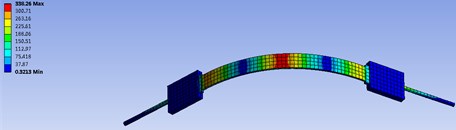
b) Stress distribution
4.4. Stress distribution and deformation of fastening belt after impact loaded
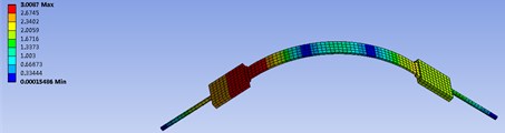
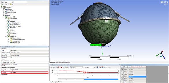
Fig. 5 shows the deformation and Stress distribution of the fastening belt under impact load. It is not difficult to find that the deformation has increased to 7.7483 mm. But it is still under the allowable range. Fig. 5 shows the stress distribution at this time. It can be seen that the maximum stress at the rubber block is 321.3 kPa. It is also far less than the tensile strength of the rubber material (14.7 MPa). Therefore, the rubber block will not break. Fig. 6 shows the upward movement about the bottom of the life raft ball after impact load applied. The maximum value is 3.5247 mm, which is far less than the depth of the mounting platform (15 mm). This means the draft ball will not leave the platform and the fastening belt is very reliable.
Fig. 5Deformation and stress distribution of the fastening belt under impact load
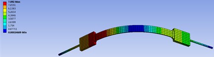
a) Deformation distribution
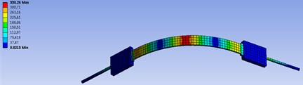
b) Stress distribution
Fig. 6The distance of life raft ball that moves upward after loading the impact load
5. Conclusions
Through modeling and doing finite element analysis with ANSYS Workbench, loading pressure, gravity, buoyancy and impact acceleration according to the actual situation. The deformation and stress distribution of the fastening belt are calculated. After comparing the maximum shape variable and maximum stress value with the design requirements and the tensile limit of material. It is determined that the rubber block and steel wire belt would not breakdown. Meanwhile, the upward distance of the life raft ball is less than the depth of the installation platform. It means that the ball would not break away from the installation platform. It can be considered that the fastening belt can perform the function of fixing and fastening the life raft ball in the working environment. The reliability of the fastening belt has also been verified. It is proved that this method can also be used to verify the impact resistance analysis of other underwater mechanical structures.
References
-
Yang Baolong Analysis of Automobile Disc Brake Performance Based on ANSYS Workbench. Guangxi University, Nan Ning, 2013.
-
LiuJianhu Current status and development approaches of anti-explosion and anti-impact technology for naval vessels. Chinese Ship Research, Vol. 11, Issue 1, 2016, p. 46-56.
-
Yun Wen High-precision pipeline system impact simulation method and test verification based on ANSYA. Marine Engineering, Vol. 39, Issue 1, 2017, p. 73-85.
-
ZhuXiang Impact test and finite element analysis of new composite column. Engineering Mechanics, Vol. 33, Issue 8, 2016, p. 158-166.
-
Zhnag Xiaoyang Comments on the anti-impact standards of major naval installations. Ship Mechanics, Vol. 15, Issue 11, 2011, p. 1322-1334.
-
Jiang Tao Analysis and application of positive and negative triangular wave in ship impact design. Journal of Naval Air Engineering college, Vol. 25, Issue 2, 2010, p. 145-148.
-
You Liwen Application of positive and negative triangular waves in the design of shipboard impact resistance. Ship Science and Technology, Vol. 32, Issue 7, 2010, p. 28-31.
-
DingXianwe Research status of the anti-impact form energy of ship integrated power system. Journal of Weapon Equipment Engineering, Vol. 39, Issue 1, 2018, p. 37-40.
-
Shen Zhongxiang Design and performance analysis of ship piping system. Marine Science and Technology, Vol. 39, Issue 5, 2017, p. 108-113.
About this article

