Abstract
In order to analyze the vibration characteristics of mistuned multistage bladed disks of an aero-engine compressor, a finite element reduction model of mistuned multistage bladed disks is established based on substructure modal synthesis method. The accuracy of the substructure model was verified by comparing calculation accuracy of the substructure model and the integral model. The influence of different modal truncation numbers on the calculation results are discussed. The vibration modes of each stage of the bladed disks are obtained, the forced response is analyzed from the perspective of strain energy. The result shows that modal truncation number, rotation softening effect, and speed have significant effects on the dynamic frequency calculation results of the multistage bladed disks. The typical mode shapes of the first 200 orders of multistage bladed disks are obtained. With the increase of mistuning standard deviation, the strain energy of multistage bladed disk system decreases gradually.
Highlights
- The finite element reduction model of multistage bladed disk was established
- The modal shapes of typical orders of multistage bladed disks are obtained.
- The vibration of the mistuned bladed disk is analyzed from the perspective of strain energy.
1. Introduction
As the heart of aircraft, the aero-engine bears the load of high temperatures, high pressures and high speeds. Its working reliability and structural integrity have always been the main problems restricting the development of high-performance engine. One of the core problems is the mistuning bladed disk vibration. Theoretically, the aero-engine compressor bladed disk system is commonly assumed to be a circular symmetrical structure, that is, tuned bladed disk. However, in reality it is not the case. Shape, mass, stiffness and natural frequency of each blade are slightly different due to factors such as material, manufacturing tolerances, wear and flutter suppression, that is, mistuning. Mistuning will cause vibration energy of the bladed disk system to concentrate on a few blades, resulting in serious vibration localization, fatigue failure, and then reduce the performance and operation life of the compressor. Because the mistuning destroys the cyclic symmetry of the bladed disk system, the cyclic symmetry model cannot be used for analysis. If the integral bladed disk model is used for dynamic analysis, the number of elements and nodes is huge, which makes the calculation difficult. Therefore, for the dynamic analysis of mistuned multistage bladed disk system, it is necessary to adopt an appropriate reduction model to greatly reduce the number of degrees of freedom of mistuned multistage bladed disk and improve the calculation speed on the premise of meeting the calculation accuracy.
The aero-engine compressor is composed of multistage disks. Interstage coupling controls the energy propagation between the disks and is regarded as the main factor leading to the difference dynamic performance between single-stage and multistage disks. However, the influence of interstage coupling is usually ignored in mistuned vibration analysis of single-stage disks [1-3].
Scholars have less research on the vibration characteristics of multistage. Bladh [1] studied the influence of interstage coupling on the dynamic performance of tuned and mistuned multistage bladed disk structure, pointed out that the dynamic characteristics of single-stage rotor depend on the selection of interstage coupling boundary conditions, and considered that the influence of interstage coupling should be considered when the excitation frequency is located in the frequency steering region of the structure. Song [2] and others studied the reduction model of multistage bladed disk rotor based on the analysis of single-stage rotor sector and concluded that the multistage rotor has mistuning response characteristics different from that of single-stage rotor. Therefore, it is necessary to deeply study the mistuning effect of multistage bladed disk structure. In order to study the maximum mistuning forced response amplitude and the worst mistuning mode of multistage bladed disk structure, Liao Haitao [3] proposed a general method to determine the maximum mistuning forced response amplitude and the worst mistuning mode by using the hybrid method of genetic algorithm and sequential quadratic programming by setting the mistuning variable as the optimization variable. Based on the lumped parameter model of typical three degree of freedom sec-tor single-stage and coupled two-stage bladed disk structures, the maximum mistuning amplitude amplification coefficient and the worst mistuning mode of the blade stiffness mistuning of the corresponding harmonic system are calculated, and the phenomenon of mistuning jump localization is revealed. An example shows that the blade has strong vibration response localization at the blade position of mistuning jump, The expression factors directly related to the localization of vibration response are constructed. Chiu [4, 5] proposed that the modal number of the system is related to the total number of blades. With the increase of bladed disk stages, the rotor system will become unstable. Xu [6] considered the coupling effect of multistage blade bending deformation and shaft torsional deformation, introduced the centrifugal stiffening effect of blade, and established the coupling vibration model including multi blade, two-stage blade disk and shaft. The differential equations of multistage disk shaft coupling vibration are derived by using Hamilton principle. The mass matrix and stiffness matrix of the system are obtained by numerical integration method, and then the coupling modes of the system are solved. The effects of natural frequency of blade disk, blade length, blade disk spacing and blade torsional angle on vibration characteristics are stud-ied. Rzadkowski [7] considered the influence of multistage coupling on the rotor dynamics of eight mistuning bladed disks on a solid shaft, calculated the overall rotation modes of eight flexible mistuning bladed disks on the shaft assembly, and obtained the natural frequencies, resonance conditions and coupling effects of blades, shafts, disks with blades and the whole shaft with disks. It was found that the mistuning system caused stronger multistage coupling than the tuned system, The greater the mistuning, the stronger the multistage coupling. Laxalde [8] proposed a stochastic reduced order modeling method for mistuned multistage bladed disk assembly. In the perturbation framework, the multi-level cyclic symmetric modeling method is used to establish the baseline reduced order model. The uncertainty is introduced into the component level modal space and further propagated in the global modal space. This leads to a compact model suitable for statistical analysis based on Monte Carlo simulation. Li [9] according to the theory of fracture mechanics and taking the stress intensity factor as the fracture criterion, proposed a three-dimensional equivalent notch model, which is simpler and more convenient than the traditional crack simulation model. And its effectiveness is analyzed. For the harsh working environment of the blade, the through cracks at the edge and middle of the blade root are considered respectively. Tran [10] uses the multi-level cyclic symmetry reduction and component mode synthesis method to establish a simplified model of multi-level cyclic structure (such as blade disk component). The component mode synthesis method can be used alone or combined with multi-level cyclic symmetry reduction to obtain the reduced model of multi-level structure. Souza [11] proposed a modeling method for analyzing the nonlinear vibration of multistage bladed disk system with inter blade disharmony and cracked blades. The modeling-strategy is based on an effective piecewise reduced order modeling method based on cyclic symmetry analysis and component pattern synthesis. A reduced order model is constructed for a single stage and assembled by projecting the motion of the interface of adjacent stages onto a set of harmonic shape functions. The analysis program allows stages to have different numbers of blades and mismatched computational grids on the interface of adjacent stages. In addition, the modeling framework is independent of the modeling methods of each stage, which makes it possible to use various existing modeling methods of a single stage. Yu [12] established the blade disk rotor system according to the finite element method. A substructure modal synthesis super element method (SMSM) with fixed interface and free interface is proposed to obtain the vibration characteristics of rotor system. Then, the free vibration results are compared with those calculated by cyclic symmetry analysis method to verify the correctness of this analysis. Sazhenkov [13] established a model platform, the platform consisted of dummy blades pair with a wedged damper. Based on the finite element method, the numerical model is simplified by Craig – Bampton and Guyan algorithm. The three-dimensional shape, nonlinear contact force, friction force, various operating loads and conditions of the parts are considered and verified by experiments. The relationship between the blade amplitude and the centrifugal load on the damper is obtained. In addition, the effect of friction coefficient on the amplitude of resonant blade is also studied. The optimum working range with maximum damping efficiency is defined. The effects of the opposite and in-phase modes of adjacent blades on the efficiency of the damper are studied. Kumar [14] focussed on the development of stochastic reduced order model for probabilistic characterisation of bladed disc systems with random spatial inhomogeneities. High fidelity finite element modelling is used to mathematically model the system. A two-step reduction strategy is applied involving reduction in the state space dimension and reduction in the stochastic dimensions. The efficacy of the proposed framework is demonstrated through two numerical examples -an academic bladed disc system and an industrial turbine rotor blade. Jena [15-23] aims at the failure of fiber reinforced composite beam structure when cracks appear. The effects of fiber orientation on FRP composite beams under different crack positions and crack depths are evaluated by analytical method, finite element method and Sugeno fuzzy method. The results show that the fiber orientation, crack location and depth have a great influence on the natural frequency and vibration mode of free vibration.
Most of the above scholars' research on the multistage bladed disk focuses on the modal vibration characteristics of the secondary disk. The models used are Lumped parameter model or cantilever beam model, and the finite element model of the multistage bladed disk system is not used. This paper based on the substructure modal synthesis method, a finite element reduction model of mistuned multistage bladed disk is established, and the accuracy of the model is verified. The vibration characteristics of mistuned multistage bladed disk are obtained through modal analysis and forced response analysis.
2. Substructure modal synthesis method
In order to reduce the calculation scale of the bladed disk system, improve the calculation and analysis efficiency, it is necessary to reduce the degrees of freedom of the mistuned multistage bladed disks. The structural dynamic equation can be expressed as:
where , , , , , , , and are mass matrix, damping matrix, Coriolis force matrix, the stiffness matrix of the structure, centrifugal stiffening effect matrix of rotating blades, rotation softening matrix, force acting on the substructure model, displacement vector, and number of blades respectively.
The general forced vibration equation of the -th substructure finite element reduced order models can be expressed as:
where , is damping matrix, and is Coriolis force matrix, where , and are given by:
where and are the first-order and second-order natural frequencies, respectively, and are the corresponding modal damping ratios.
The Coriolis force matrix obtained as:
where is the shape function matrix; n is the total number of elements; is the rotational matrix. The rotational matrix obtained as:
where is the stiffness matrix of the structure, is the centrifugal stiffening effect matrix of the rotating blades, and is the rotation-softening matrix.
The displacement vector is composed of the degree of freedom at the boundary and the internal freedom of the non-interface, that is:
The Eq. (2) can be presented as below:
where, is the interface force. Let the substructure of the interface to be fixed, even if , it is possible to obtain as follows:
From this, the normalized mode is solved, that is , where, – low order modal, – high order modal.
This modal set satisfies the following conditions:
where, , , is a identity matrix.
When the higher order mode sets are omitted, and the lower order mode set is selected to form the master modal set of the substructures, that is:
If the fixed interface method is used, can be expressed as:
Definition is the constrained modal set:
The Ritz base vector of the substructure:
Coordinate transformation is:
Through the Eq. (15), it can achieve the transformation of the equation of motion from physical coordinates to modal coordinates:
where:
The coordinate transformation of Eq. (15), which uses only low-order mode and ignores the high-order mode, that is used to adapt the mode truncation, so the node degree of freedom is greatly reduced, will be made for obtaining the substructure formula deduced from the Eq. (15):
If the rigid connection interface is considered, through the force balance and displacement coordination condition, it is possible to obtain as follows:
The non-independent coordinate can be transformed into the equation of motion of the generalized coordinate in the following form:
That is:
The Eq. (21) is transformed into the equation of motion of the generalized coordinate by using this form :
where, , , , .
The Eq. (22) can be adopted to solve the natural frequency of the system and the vibration mode under the generalized coordinates . The vibration mode under the generalized coordinates can be returned to the physical coordinates by the coordinate transformation from Eq. (21) and form transformation from Eq. (15), thus the vibration mode of the physical system coordinates can be obtained.
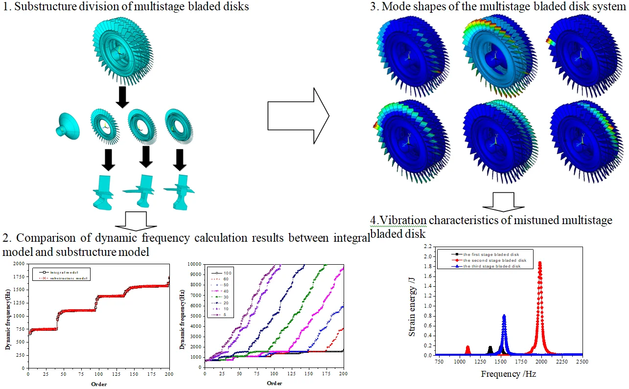
Fig. 1Substructure division process of multistage bladed disks
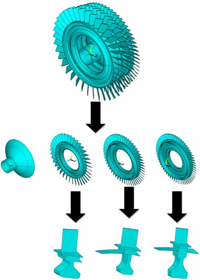
The finite element model of three-stage bladed disk is based on ANSYS 15.0. A three-stage bladed disks are divided into substructures is shown in Fig. 1. So as to model of three-stage bladed disk in ANSYS, solid185 elements are used. The mechanical properties of the three-stage bladed disk is shown in Table 1.
Table 1The mechanical properties of the three-stage bladed disk
Blade material property | Property value | Disk material property | Property value |
Mass density | 4400kg⋅m−3 | Mass density | 8200kg⋅m−3 |
Modulus of elasticity | 114 GPa | Modulus of Elasticity | 166 GPa |
Poisson’s ratio | 0.3 | Poisson’s ratio | 0.3 |
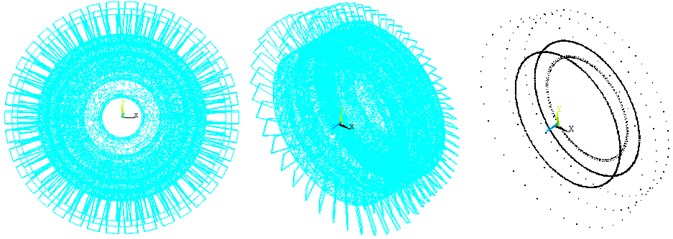
The blade of each stage bladed disk and disk connected with it are divided into one substructure. The first stage bladed disk is divided into 38 substructures, the second stage bladed disk is divided into 52 substructures, and the third stage bladed disk is divided into 60 substructures. The finite element model of the three-stage bladed disk system after the substructure integrated condensed super element is shown in Fig. 2.
Fig. 2Finite element model of multistage bladed disks after condensing super element
3. Modal analysis
In this section, finite element analysis is used o obtain the natural frequency and mode shape, ANSYS package (Released version 15.0) is used. Through the modal analysis between the integral model and the substructure model, the first 500 natural frequencies and vibration modes are obtained respectively, and compared to verify the accuracy of the substructure model and determine the appropriate modal truncation number. The block diagram of modal analysis is shown in Fig. 3.
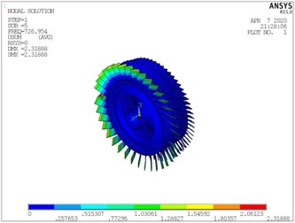
The aero-engine compressor bladed disks system is a high-speed rotating power system. Whether the effect of rotating speed is considered will affect the accuracy of the dynamic analysis. As shown in Fig. 4 and Table 2, the natural frequency calculation comparison between the integral bladed disks model and the substructure model is shown. The effect caused by the rotation of the bladed disk is considered in the calculation, and the dynamic frequency of the bladed disks system is obtained. It can be seen from the figure that the substructure model is in good agreement with the calculation results of the integral blade disk model within 225 order, which shows that the substructure model still has high calculation accuracy and can meet the calculation requirements on the premise of ignoring the high-order modes, reducing the number of degrees of freedom of the model and improving the calculation speed.
In order to verify the accuracy of the calculation results of the substructure model, the mode shapes of the integral bladed disks model and the substructure model are compared, and the comparison results are shown in Fig. 5. It can be seen from the figure that the vibration modes of the substructure under each mode are consistent with the calculation results of the integral bladed disk model, and the calculation accuracy of the substructure model is high, which can meet the requirements of the next dynamic calculation.
Fig. 3The block diagram of modal analysis
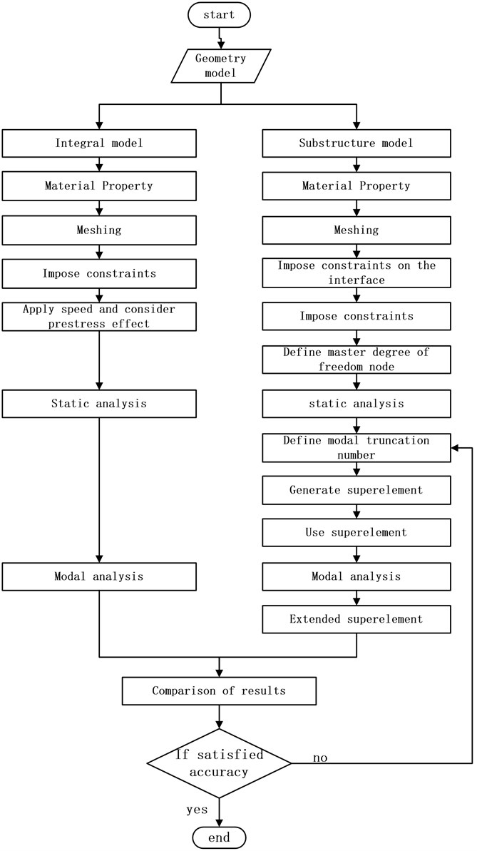
Fig. 4Comparison of dynamic frequency calculation results between integral model and substructure model
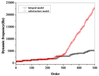
a) 500 order
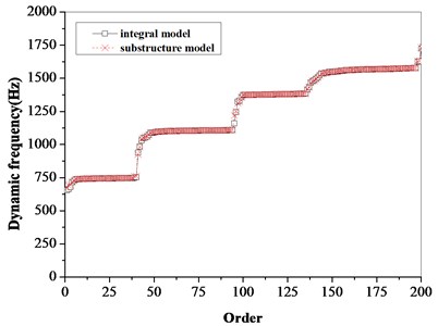
b) 200 order
Table 2Comparison of dynamic frequency calculation results between integral model and substructure model
Order | Natural frequency (Hz) | Absolute error (%) | |
Integral model | Substructure model | ||
1 | 655.07 | 673.62 | –0.02832 |
2 | 662.14 | 691.52 | –0.04437 |
3 | 679.52 | 695.56 | –0.0236 |
4 | 715.88 | 717.13 | –0.00175 |
5 | 724.64 | 726.69 | –0.00283 |
6 | 737.13 | 737.05 | 0.000109 |
7 | 738.29 | 738.07 | 0.000298 |
8 | 739.4 | 739.49 | –0.00012 |
9 | 740.03 | 739.82 | 0.000284 |
10 | 741.11 | 740.84 | 0.000364 |
11 | 741.57 | 741.29 | 0.000378 |
12 | 742.01 | 742.03 | –2.7E-05 |
13 | 742.55 | 742.42 | 0.000175 |
14 | 742.69 | 742.6 | 0.000121 |
15 | 742.92 | 742.8 | 0.000162 |
16 | 743.07 | 742.98 | 0.000121 |
17 | 743.35 | 743.19 | 0.000215 |
18 | 743.43 | 743.48 | –6.7E-05 |
19 | 743.55 | 743.95 | –0.00054 |
20 | 743.83 | 744.03 | –0.00027 |
21 | 744.32 | 744.14 | 0.000242 |
22 | 744.63 | 744.29 | 0.000457 |
23 | 744.71 | 744.58 | 0.000175 |
24 | 744.92 | 744.62 | 0.000403 |
25 | 745 | 744.64 | 0.000483 |
26 | 745.07 | 744.88 | 0.000255 |
27 | 745.11 | 745.11 | 0 |
28 | 745.56 | 745.26 | 0.000402 |
29 | 745.62 | 745.31 | 0.000416 |
30 | 745.69 | 745.35 | 0.000456 |
31 | 745.75 | 745.55 | 0.000268 |
32 | 745.77 | 745.57 | 0.000268 |
33 | 746.12 | 745.75 | 0.000496 |
34 | 746.29 | 745.83 | 0.000616 |
35 | 746.44 | 745.88 | 0.00075 |
Fig. 5Comparison of modal shapes between integral model and substructure model
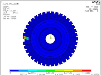
a) The fourth order of integral model

b) The fourth order of substructure model
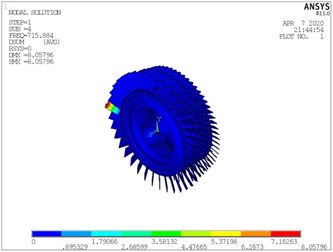
c) The fourth order of integral model
d) The fourth order of substructure model
e) The fifth order of integral model
f) The fifth order of substructure model
g) The fifth order of integral model
h) The fifth order of substructure model
The basic idea of degree of freedom reduction by substructure modal synthesis method is to ignore the high-order modes and intercept the low-order modes. On the premise of meeting the calculation accuracy of the low-order model, the number of degrees of freedom of the dynamic model is reduced by selecting the appropriate mode truncation number, so as to improve the calculation speed. Fig. 6 shows the dynamic frequency comparison of the three-stage bladed disk system when different modal truncation numbers are selected. It can be seen from the figure that the accuracy of low-order modal calculation increases with the increase of modal truncation number. From Fig. 6(b), when the modal truncation number is greater than 30, the first 25 modal calculation results can meet the requirements. When the modal truncation number is greater than 60, the accuracy of the first 175 modal results is higher.
Fig. 6Effect of different modal truncation numbers on dynamic frequency of multistage bladed disk system
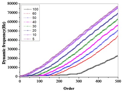
a) 500 order
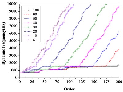
b) 200 order
For rotating machinery, the rotary softening effect has a certain impact on the dynamics of the bladed disk system. The rotary softening effect is considered in the calculation of multistage bladed disks, and the calculation results shown in Fig. 7 are obtained. It can be seen from the figure that the rotating software effect has a certain impact on the dynamic characteristics of the bladed disk system.
Fig. 7Effect of rotary softening on dynamic frequency of bladed disks
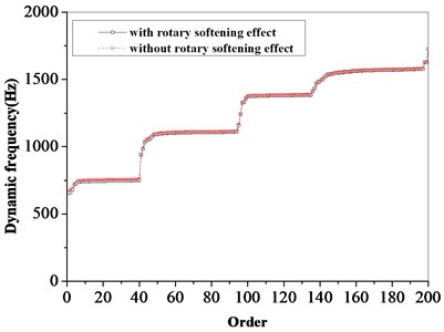
a) Integral model

b) Substructure model
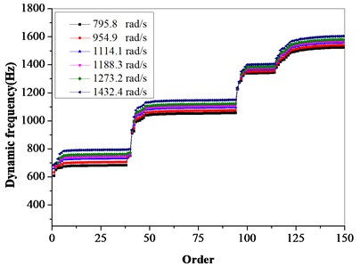
The rotating speed of the bladed disk system has a certain impact on the dynamic frequency of the bladed disk system. It can be seen from Table 3 and Fig. 8 that the dynamic frequency gradually increases with the increase of rotating speed.
The first 200 order dynamic frequencies and mode shapes of multistage bladed disk system are shown in Table 4.
Table 3Effect of rotating speed on dynamic frequency of bladed disks
Order | Speed rad/s | |||||
795.8 | 954.9 | 1114.1 | 1188.3 | 1273.2 | 1432.4 | |
1 | 607.49 | 632.59 | 660.58 | 673.86 | 685.53 | 687.02 |
2 | 650.31 | 671.85 | 688.52 | 692.8 | 697.57 | 696.34 |
3 | 662.54 | 679.43 | 693.04 | 696.82 | 700.07 | 729.1 |
4 | 664.15 | 682.56 | 704.67 | 717.27 | 732.62 | 764.37 |
5 | 666.3 | 688.64 | 714.12 | 726.95 | 742.09 | 772.93 |
6 | 674.65 | 697.64 | 723.85 | 737.06 | 752.67 | 784.49 |
7 | 675.57 | 698.59 | 724.84 | 738.07 | 753.71 | 785.59 |
8 | 676.92 | 699.97 | 726.27 | 739.53 | 755.2 | 787.17 |
9 | 677.14 | 700.23 | 726.57 | 739.85 | 755.55 | 787.56 |
10 | 678.03 | 701.15 | 727.53 | 740.84 | 756.56 | 788.63 |
11 | 678.47 | 701.6 | 727.98 | 741.3 | 757.02 | 789.11 |
12 | 679.16 | 702.3 | 728.71 | 742.03 | 757.77 | 789.89 |
13 | 679.5 | 702.66 | 729.09 | 742.42 | 758.17 | 790.31 |
14 | 679.65 | 702.82 | 729.26 | 742.6 | 758.36 | 790.52 |
15 | 679.83 | 703.01 | 729.46 | 742.8 | 758.56 | 790.73 |
16 | 680.07 | 703.22 | 729.65 | 742.98 | 758.73 | 790.88 |
17 | 680.22 | 703.39 | 729.84 | 743.19 | 758.96 | 791.13 |
18 | 680.5 | 703.68 | 730.13 | 743.48 | 759.25 | 791.43 |
19 | 681.01 | 704.17 | 730.61 | 743.95 | 759.72 | 791.89 |
20 | 681.05 | 704.23 | 730.68 | 744.03 | 759.8 | 791.99 |
21 | 681.14 | 704.33 | 730.79 | 744.14 | 759.91 | 792.11 |
22 | 681.37 | 704.53 | 730.96 | 744.29 | 760.05 | 792.2 |
23 | 681.66 | 704.84 | 731.26 | 744.58 | 760.31 | 792.37 |
24 | 681.69 | 704.85 | 731.28 | 744.62 | 760.39 | 792.55 |
25 | 681.73 | 704.87 | 731.3 | 744.64 | 760.41 | 792.59 |
26 | 681.92 | 705.09 | 731.54 | 744.88 | 760.65 | 792.82 |
27 | 682.19 | 705.35 | 731.78 | 745.12 | 760.87 | 793.02 |
28 | 682.32 | 705.48 | 731.92 | 745.26 | 761.02 | 793.19 |
29 | 682.38 | 705.54 | 731.97 | 745.31 | 761.07 | 793.24 |
30 | 682.42 | 705.58 | 732.01 | 745.35 | 761.11 | 793.27 |
31 | 682.66 | 705.81 | 732.22 | 745.55 | 761.3 | 793.42 |
32 | 682.67 | 705.82 | 732.24 | 745.57 | 761.32 | 793.48 |
33 | 682.85 | 706 | 732.42 | 745.75 | 761.51 | 793.65 |
34 | 682.92 | 706.07 | 732.5 | 745.83 | 761.59 | 793.75 |
35 | 682.96 | 706.11 | 732.54 | 745.88 | 761.64 | 793.8 |
Fig. 8Effect of rotating speed on dynamic frequency of bladed disks
It can be seen from Table 4 that the vibration of the first 40 stage bladed disks system is mainly concentrated in the first stage bladed disk, the vibration mode is mainly the first-order bending vibration of the blades. The 41st and 42nd modes are mainly the coupled vibration of the second-stage and third-stage blades. The first-order bending vibration of the second stage blades is the main mode of 43th-94th. the 99th-135th vibration modes are mainly the first-order torsion vibration of the first stage blades. the 136th-197thare the first-order bending vibration of the third stage blades. the 198th-200th are the coupled vibration of the three-stage blades and disks.
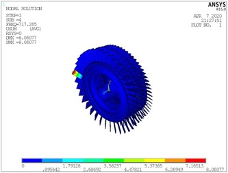
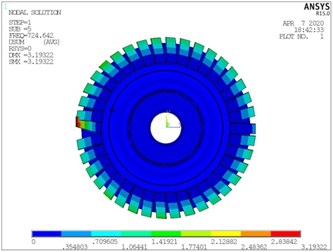
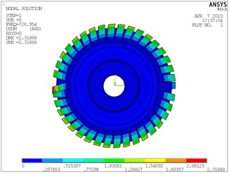
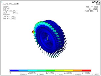
Table 4First 200th order dynamic frequencies and mode shapes of the multistage bladed disk system
Order number | Dynamic frequency/Hz | Vibration mode | Mode pattern of a typical order |
1 | 655.073 | First-order bending vibration of the first-stage blades | 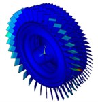 |
2 | 662.144 | Coupled vibration of the first-stage and second-stage blades and disks | 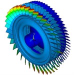 |
3-4 | 679.515-715.884 | First-order bending vibration of the first-stage blades | 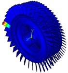 |
5-40 | 724.642-751.635 | First-order bending vibration of the first-stage blades | 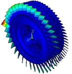 |
41-42 | 938.904-982.939 | Coupled vibration of the second-stage and third-stage blades | 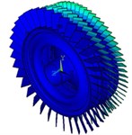 |
43-94 | 1031.86-1109.85 | First-order bending vibration of the second-stage blades | 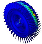 |
95 | 1159.27 | Coupled vibration of the first-stage and second-stage blades and disks | 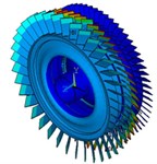 |
96 | 1242.65 | Coupled vibration of the three-stage blades and disks | 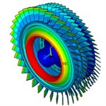 |
97 | 1323.47 | First-order blades torsion vibration of the first-stage | 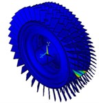 |
98 | 1331.06 | Coupled vibration of the three-stage blades and disks | 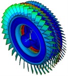 |
99-135 | 1357.57-1385.17 | First-order blade torsion vibration of the first-stage blades | 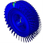 |
136-197 | 1413.1-1577.73 | First-order bending vibration of the third-stage blades |  |
198-200 | 1625.72-1724.05 | Coupled vibration of the three-stage blades and disks | 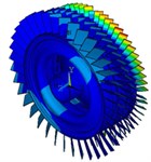 |
4. Vibration characteristics of mistuned multistage bladed disks
The flow excitation acting on the compressor blades is often simply to a single point sinusoidal excitation acting on the blade tip. According to the modal vibration analysis results, the excitation frequency range is 650 Hz-2500 Hz. the mistuning value is normally distributed, and the vibration characteristics of multistage bladed disks with mistuning standard deviation of 1 % - 5 % are calculated.
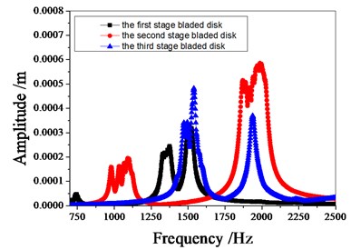
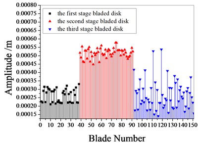
Fig. 9 shows the amplitude frequency characteristics of the multistage bladed disks system. as can be seen from Fig. 9, the mistuning causes the amplitude peak resonance band of the second stage blades disk to widen. the amplitude peak of the second stage bladed disk increases gradually with the increase of mistuning standard deviation near 1980 Hz. Fig. 10 shows the maximum amplitude of each blade of multistage bladed disks system when the excitation frequency is 1980 Hz. the blades with large amplitude are concentrated in the second stage bladed disk. It can be seen from Table 5 that the mistuning increases the maximum vibration amplitude of the bladed disk system, the maximum vibration amplitude of bladed disk system occurs when the standard deviation of mistuning is 2 %.
Fig. 9Amplitude frequency characteristics of bladed disk system
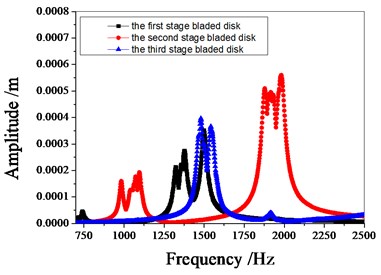
a) Tuned bladed disk
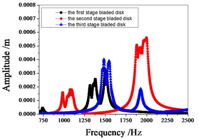
b) 1 % mistuned bladed disk
c) 2 % mistuned bladed disk
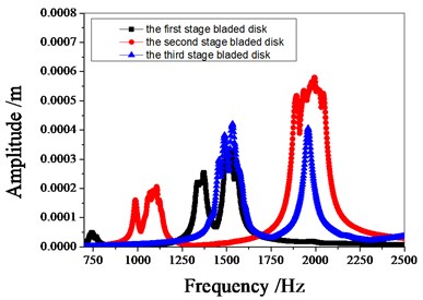
d) 3 % mistuned bladed disk
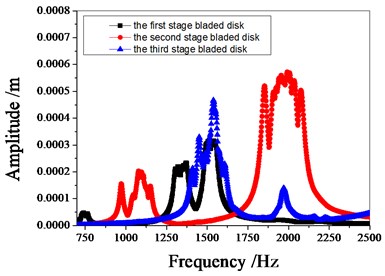
e) 4 % mistuned bladed disk
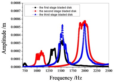
f) 5 % mistuned bladed disk.
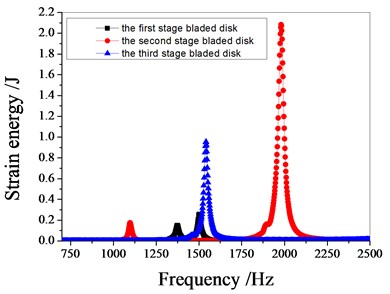
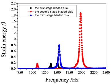
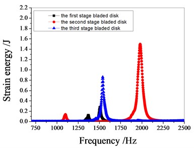
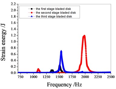
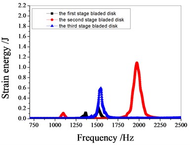
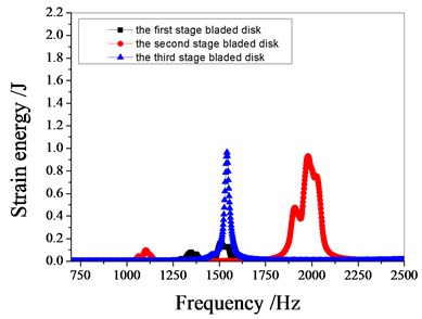
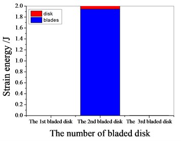
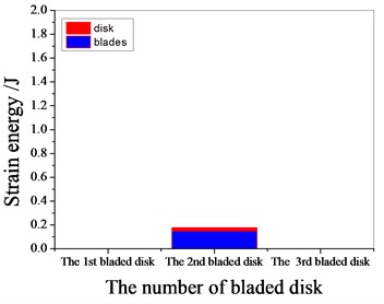
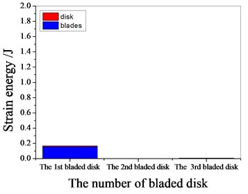
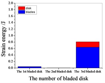
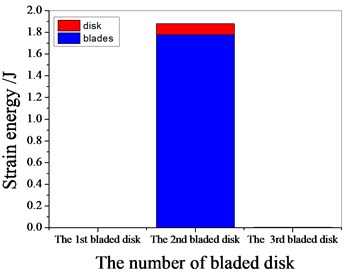
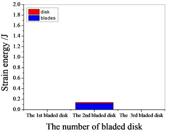
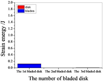
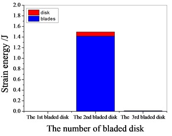
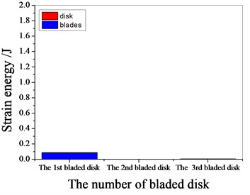
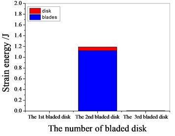
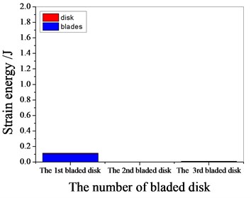
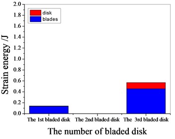
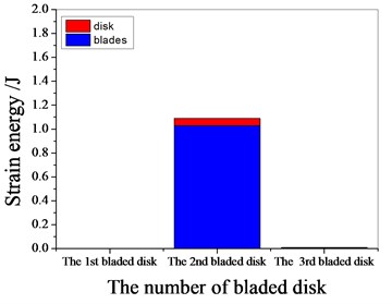
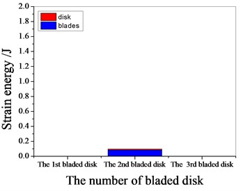
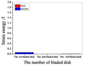
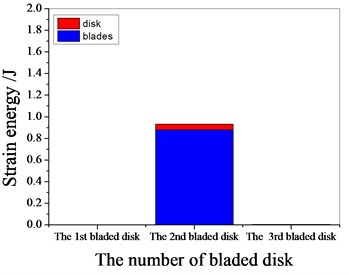
Fig. 11 shows the characteristics of strain energy of multistage bladed disk system with excitation frequency. the resonant frequencies of the blade disk system are around 1100 Hz, 1370 Hz, 1540 Hz and 1980 Hz respectively. When the resonance frequency is 1100 Hz, the strain energy of the bladed disk system is mainly contributed by the second stage bladed disk. When the resonance frequency is 1370 Hz, the strain energy of the bladed disk system is mainly contributed by the first stage bladed disk. When the resonance frequency is 1540 Hz, the strain energy of the bladed disk system is mainly contributed by the third stage bladed disk. When the resonance frequency is 1980 Hz, the strain energy of the bladed disk system is mainly contributed by the second stage bladed disk. with the increase of the standard deviation of mistuning, the maximum strain energy of the bladed disk system decreases gradually.
Fig. 10The maximum amplitude of each blades
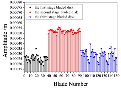
a) Tuned bladed disk
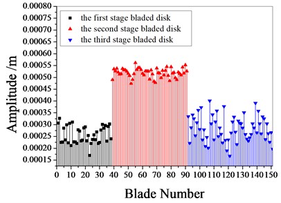
b) 1 % mistuned bladed disk
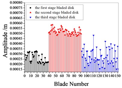
c) 2 % mistuned bladed disk
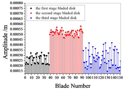
d) 3 % mistuned bladed disk
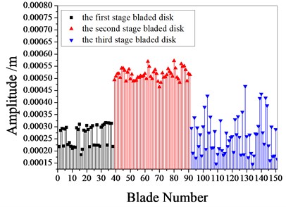
e) 4 % mistuned bladed disk
f) 5 % mistuned bladed disk
Table 5The maximum amplitude of the multistage bladed disk system.
Mistuning | The maximum amplitude (×10-4 m) | |||
The first stage | The second stage | The third stage | The maximum amplitude of bladed disk | |
0 % (tuned) | 3.505 | 5.545 | 3.509 | 5.545 |
1% | 3.269 | 5.61 | 3.772 | 5.61 |
2% | 3.28 | 5.856 | 4.824 | 5.856 |
3% | 3.238 | 5.688 | 4.207 | 5.688 |
4% | 3.159 | 5.69 | 4.676 | 5.69 |
5% | 3.312 | 5.777 | 4.173 | 5.777 |
Fig. 11Strain energy of bladed disk
a) Tuned bladed disk
b) 1 % mistuned bladed disk
c) 2 % mistuned bladed disk
d) 3 % mistuned bladed disk
e) 4 % mistuned bladed disk
f) 5 % mistuned bladed disk
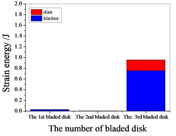
Figs. 12-17 shows the distribution of strain energy of each blade disk at the resonance peak of tuned and mistuned bladed disk system.
It can be seen from Fig. 11 to Fig.17, the resonance frequency is around 1100 Hz or 1980 Hz, the strain energy is mainly concentrated in the second stage bladed disk, dominated by blade vibration, the resonance frequency is near 1980 Hz and the strain energy is large. the resonance frequency is around 1370 Hz or 1540 Hz, and the strain energy is mainly concentrated in the first stage bladed disk and the third stage blade disk, the resonance frequency is around 1370 Hz, the strain energy is small, and the vibration of the first stage bladed disk is mainly. the resonance frequency is around 1540 Hz, and the strain energy is large, mainly the third stage blade disk vibration. with the increase of mistuning standard deviation, the vibration energy of each stage of bladed disk decreases gradually.
Fig. 12Strain energy of tuned bladed disk

a) 1097.7 Hz

b) 1373 Hz
c) 1541.7 Hz
d) 1978.3 Hz
Fig. 13Strain energy of 1 % mistuned bladed disk
a) 1097.7 Hz
b) 1373 Hz
c) 1541.7 Hz
d) 1978.3 Hz
Fig. 14Strain energy of 2 % mistuned bladed disk
a) 1101.4 Hz
b) 1369.65 Hz

c) 1539.85 Hz
d) 1980.15 Hz
Fig. 15Strain energy of 3 % mistuned bladed disk

a) 1094 Hz
b) 1367.8 Hz
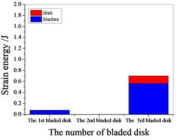
c) 1538 Hz
d) 1987.55 Hz
Fig. 16Strain energy of 4 % mistuned bladed disk

a) 1099.55 Hz
b) 1365.95 Hz
c) 1532.45 Hz
d) 1974.6 Hz
Fig. 17Strain energy of 5 % mistuned bladed disk
a) 1103.25 Hz
b) 1373.35 Hz

c) 1541.7 Hz
d) 1980.15 Hz
5. Conclusions
The vibration characteristics of multistage mistuned bladed disk system were studied. Based on the substructure modal synthesis method, the finite element reduction model of multistage bladed disk was established, the accuracy of substructure model and integral bladed disk model is compared, and the influence of different modal truncation numbers on the calculation accuracy of substructure model is discussed. Through the modal analysis of multistage bladed disk, the effects of rotating softening effect and rotating speed on the dynamic frequency of blade disk system are analyzed. the modal shapes of typical orders of multistage bladed disks are obtained. Through the forced response analysis of the mistuned multistage bladed disk, the amplitude frequency characteristics of the tuned and mistuned bladed disk are obtained, the influence of different mistuned standard deviations on the vibration characteristics of the bladed disk system is discussed, and the vibration of the mistuned bladed disk is analyzed from the perspective of strain energy. The following points are concluded through modal analysis and vibration analysis:
1) with the increase of modal truncation number, the calculation accuracy of substructure model increases gradually.
2) the rotating speed has a significant influence on the dynamic frequency of multistage bladed disk system. with the increase of rotating speed, as a result the dynamic frequency increases.
3) the first-order bending vibration of the blade is the main form of the low-order vibration of the first 200 order multistage blade disk.
4) the maximum strain energy of each stage bladed disk system decreases with the increase of mistuning standard deviation.
References
-
R. Bladh, M. P. Castanier, and C. Pierre, “Effects of multistage coupling and disk flexibility on mistuned bladed disk dynamics,” Journal of Engineering for Gas Turbines and Power, Vol. 125, No. 1, pp. 121–130, Jan. 2003, https://doi.org/10.1115/1.1498267
-
S. H. Song, M. P. Castanier, and C. Pierre, “Multi-stage modeling of turbine engine rotor vibration,” in ASME 2005 International Design Engineering Technical Conferences and Computers and Information in Engineering Conference, pp. 1533–1543, Jan. 2005, https://doi.org/10.1115/detc2005-85740
-
Liao, H. T., Wang, J. J., Li, and Q. H., “Mistuned forced response characteristics analysis of mistuned multi-stages bladed disks,” Journal of Vibration and Shock, Vol. 30, No. 2, pp. 29–36, Mar. 2011, https://doi.org/10.13465/j.cnki.jvs.2011.03.037
-
Y.-J. Chiu and D.-Z. Chen, “The coupled vibration in a rotating multi-disk rotor system,” International Journal of Mechanical Sciences, Vol. 53, No. 1, pp. 1–10, Jan. 2011, https://doi.org/10.1016/j.ijmecsci.2010.10.001
-
Y.-J. Chiu, X.-Y. Li, Y.-C. Chen, S.-R. Jian, C.-H. Yang, and I.-H. Lin, “Three methods for studying coupled vibration in a multi flexible disk rotor system,” Journal of Mechanical Science and Technology, Vol. 31, No. 11, pp. 5219–5229, Nov. 2017, https://doi.org/10.1007/s12206-017-1015-2
-
Xu, Z. L., Zhou, Z., and X., “Torsional coupled vibration characteristics of multi-stage blade disc-shaft system of aeroengine,” Journal of Traffic and Tansportation Engineering, Vol. 19, No. 3, pp. 79–88, Jun. 2019, https://doi.org/10.19818/j.cnki.1671-1637.2019.03.009
-
R. Rzadkowski and A. Maurin, “Multistage coupling of eight mistuned bladed disk on a solid shaft: Part 1-free vibration analysis,” in ASME Turbo Expo 2012: Turbine Technical Conference and Exposition, pp. 531–540, Jun. 2012, https://doi.org/10.1115/gt2012-68391
-
D. Laxalde and C. Pierre, “Modelling and analysis of multi-stage systems of mistuned bladed disks,” Computers and Structures, Vol. 89, No. 3-4, pp. 316–324, Feb. 2011, https://doi.org/10.1016/j.compstruc.2010.10.020
-
Z. Li, T. Zhao, H. Kou, H. Zhang, and H. Yuan, “Vibration characteristics of multi-stage blade-disk-shaft integrated structure with three-dimensional crack,” Journal of Vibration Engineering and Technologies, Vol. 9, No. 4, pp. 597–611, Jun. 2021, https://doi.org/10.1007/s42417-020-00251-0
-
D.-M. Tran, “Reduced models of multi-stage cyclic structures using cyclic symmetry reduction and component mode synthesis,” Journal of Sound and Vibration, Vol. 333, No. 21, pp. 5443–5463, Oct. 2014, https://doi.org/10.1016/j.jsv.2014.06.004
-
K. D. ’Souza, A. Saito, and B. I. Epureanu, “Reduced-order modeling for nonlinear analysis of cracked mistuned multistage bladed-disk systems,” AIAA Journal, Vol. 50, No. 2, pp. 304–312, Feb. 2012, https://doi.org/10.2514/1.j051021
-
Y. Yu, X. Jin, Y. Fu, and T. Zhao, “Study on the coupled vibration characteristics of a two-stage bladed disk rotor system,” Applied Sciences, Vol. 11, No. 18, p. 8600, Sep. 2021, https://doi.org/10.3390/app11188600
-
N. Sazhenkov, I. Semenova, M. Nikhamkin, and S. Semenov, “A substructure-based numerical technique and experimental analysis of turbine blades damping with underplatform friction dampers,” Procedia Engineering, Vol. 199, pp. 820–825, 2017, https://doi.org/10.1016/j.proeng.2017.09.085
-
R. Kumar, S. F. Ali, S. Jeyaraman, and S. Gupta, “Uncertainty quantification of bladed disc systems using data driven stochastic reduced order models,” International Journal of Mechanical Sciences, Vol. 190, p. 106011, Jan. 2021, https://doi.org/10.1016/j.ijmecsci.2020.106011
-
P. C. Jena, D. R. Parhi, and G. Pohit, “Dynamic Investigation of FRP cracked beam using neural network technique,” Journal of Vibration Engineering and Technologies, Vol. 7, No. 6, pp. 647–661, Dec. 2019, https://doi.org/10.1007/s42417-019-00158-5
-
Parida S. P., Jena P. C., and Dash R. R., “Dynamic analysis of laminated composite beam using Timoshenko beam Theory,” International Journal of Engineering and Advanced Technology, Vol. 8, No. 6, pp. 190–196, 2019.
-
Jena P. C., Dash R. R., Parhi D. R., and Pohit G., “Fault measurement in composite structure by fuzzy-neuro hybrid technique from the natural frequency and fibre orientation,” Journal of Vibration Engineering and Technologies, Vol. 5, No. 2, pp. 124–36, Apr. 2017.
-
P. C. Jena, D. R. Parhi, and G. Pohit, “Dynamic study of composite cracked beam by changing the angle of bidirectional fibres,” Iranian Journal of Science and Technology, Transactions A: Science, Vol. 40, No. 1, pp. 27–37, Mar. 2016, https://doi.org/10.1007/s40995-016-0006-y
-
Pankaj Charan, Dayal R. Parhi, and G. Pohit, “Theoretical, numerical (FEM) and experimental Analysis of composite cracked beams of different boundary conditions using vibration mode shape curvatures,” International Journal of Engineering and Technology, Vol. 6, No. 2, pp. 509–518, May 2014.
-
S. P. Parida and P. C. Jena, “Dynamic analysis of cracked FGM cantilever beam,” in Lecture Notes in Mechanical Engineering, Singapore: Springer Singapore, 2020, pp. 339–347, https://doi.org/10.1007/978-981-15-2696-1_33
-
B. B. Bal, S. P. Parida, and P. C. Jena, “Damage assessment of beam structure using dynamic parameters,” Lecture Notes in Mechanical Engineering, pp. 175–183, 2020, https://doi.org/10.1007/978-981-15-2696-1_17
-
P. Charan Jena, “Identification of crack in SiC composite polymer beam using vibration signature,” Materials Today: Proceedings, Vol. 5, No. 9, pp. 19693–19702, 2018, https://doi.org/10.1016/j.matpr.2018.06.331
-
P. C. Jena, “Free Vibration analysis of short bamboo fiber based polymer composite beam structure,” Materials Today: Proceedings, Vol. 5, No. 2, pp. 5870–5875, 2018, https://doi.org/10.1016/j.matpr.2017.12.185
About this article

This research was funded by project of the National Natural Science Foundation of China (No. 51805076, No. 51775093 and No. U1708255), Doctoral research initiation fund of Liaoning Provincial (2020-BS-156), Shenyang Youth Science and technology innovation talent project (RC200006) and Scientific research fund project of Liaoning Provincial Department of Education (LG202008), the construction plan of scientific research and innovation team of Shenyang Ligong University (SYLU202101), Comprehensive reform project of graduate education of Shenyang Ligong University (2021DSTD004, 2021PYPT006).
