Abstract
Vibratory treatment is widely used in various industries for performing finishing technological operations, e.g., lapping, polishing, glazing, strengthening (hardening), etc. The problems of maximizing the treatment accuracy and performance of vibratory technological equipment provide the necessity of optimizing the motion trajectory (path) of the corresponding working member. The main purpose of these investigations is to substantiate the possibilities of generating the translational (reciprocating) motion and plane (plane-parallel) oscillations of the working members of vibratory lapping-polishing machines. The research methodology consists of the following stages: substantiating the ideas of improving the vibratory lapping-polishing machines; designing the dynamic diagrams of the machines’ oscillatory systems; developing the mathematical models to describe their dynamic behavior; numerical modeling of the machines’ motion conditions. The obtained results present the possible motion trajectories (paths) of the working member (lap, polisher, grazer, etc.). The main scientific novelty of these investigations is substantiating the idea and possibilities of implementing various motion conditions of the working member for adjusting the vibratory lapping-polishing machine in accordance with the technological requirements, as well as for increasing the wear-out period and durability (normal operating period) of the working member. The obtained results can be used for improving the performance and accuracy of similar vibratory lapping-polishing machines.
Highlights
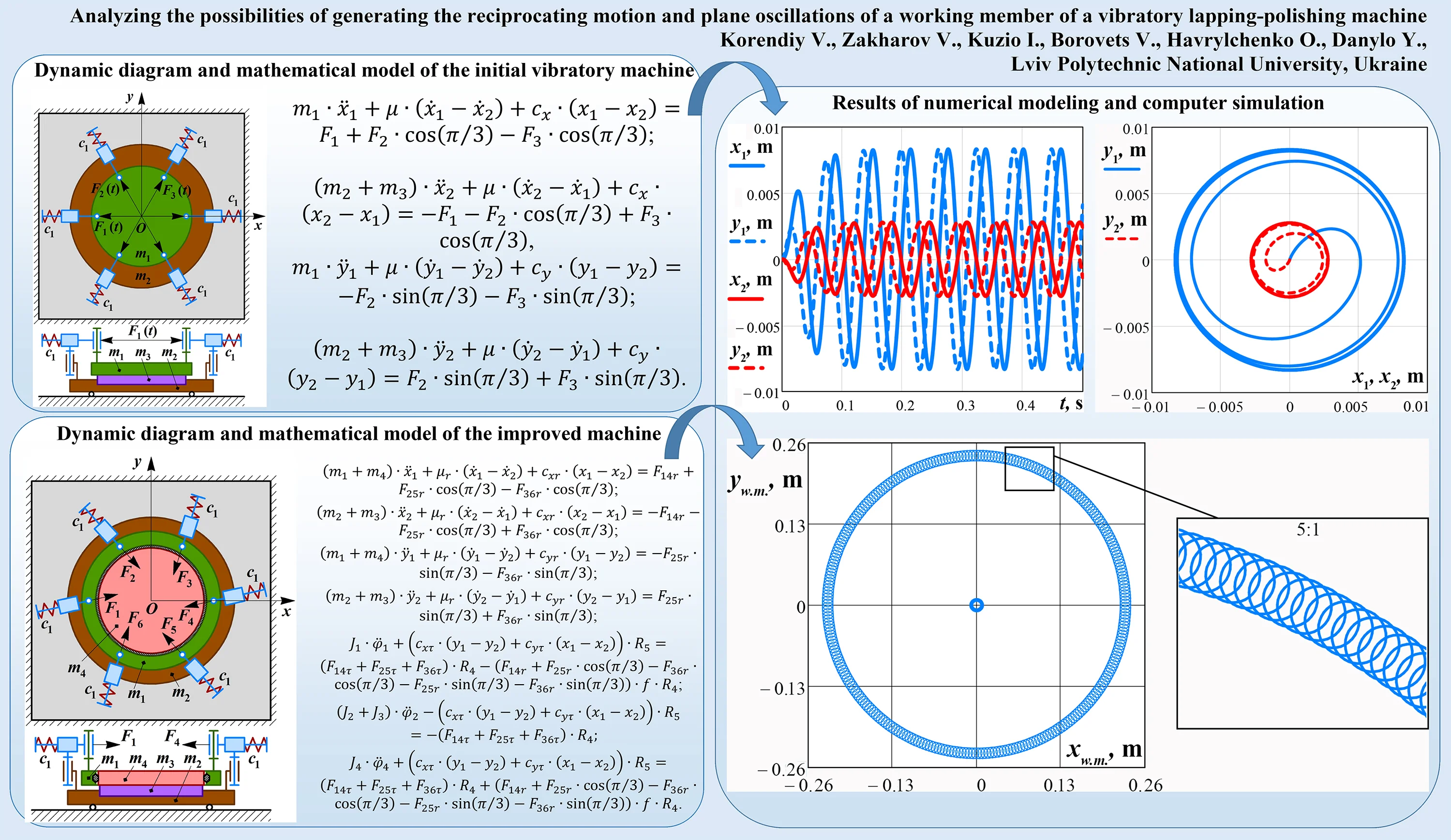
- The initial two-mass and the improved three-mass designs of the machine’s oscillatory systems are considered, and the corresponding mathematical models describing their motion conditions are derived.
- The numerical modeling of the system oscillations is carried out in the MathCad software. Each point of the working member and carrier of the initial machine moves in a circle of a specific radius.
- The improved machine allows the working member to perform plane oscillations where its center point is in the reciprocating motion, and the peripheral points slowly rotate around this center.
1. Introduction
Vibratory treatment is usually used for performing various finishing technological operations, e.g., lapping, polishing, glazing, grinding, strengthening (hardening), etc. As an example, the vibratory finishing treatment can be implemented while manufacturing semiconductors [1]. As well, the mentioned above technological operations are widely used in pharmaceutical, chemical, agricultural, mining, machine-building industries, etc. In many cases, the vibratory treatment is performed using bowls (chambers, containers, etc.) subjected to simultaneous rotation and vibrations. The dynamics of the vibratory machine with a rotating container filled with the working medium and the parts being treated are investigated in [2]. The papers [3, 4] consider the metal removal processes during the vibratory treatment of various workpieces in a fluidized medium with abrasive granules. While conducting the vibratory finishing treatment, it is necessary to provide the prescribed accuracy at the maximal performance and durability of the corresponding technological equipment. In this case, much attention should be paid to the kinematics and dynamics of the working member (lap, polisher, glazer, etc.) allowing for decreasing its wear and extending the wear-our period.
The vast majority of the existing lapping-polishing machines are based on planetary-type mechanisms, which provide two simultaneous rotary motions of the working members (laps, polishers) and the carriers (with the workpieces being treated). The differences between the double-sided lapping processes applied for the parts with concave and convex surface shapes are thoroughly investigated in [5]. The paper [6] is focused on developing the simulation model for studying the residual stresses on the surfaces of the workpiece and the substrate during the double-sided lapping process. In [7], the authors analyzed the influence of the workpiece rotational speed on the grit’s paths generated during the double-sided planetary-type lapping. The peculiarities of implementing the vibratory polishing for improving the roughness and tolerance parameters of machine parts after depositing hard coatings are studied in [8]. The enhanced driving system of a single-sided planetary-type lapping machine is proposed in [9]. The paper [10] is devoted to developing a novel method of evaluating the friction and wear levels during the lapping process. In [11], the influence of various lapping conditions on the roughness parameters is studied taking into account the characteristics of the working medium and the material of the workpieces being treated. The novel method of dressing the metal working members of lapping machines is proposed and experimentally tested in [12].
Unlike numerous publications devoted to the lapping-polishing processes, the present research is focused on performing the non-traditional finishing treatment with the help of vibratory equipment. The initial design of the electromagnetically-driven vibratory lapping machine was proposed in [13]. The dynamics of the lapping process is thoroughly studied in [14, 15], and the corresponding experimental investigations are analyzed in [16]. Based on the authors’ previous investigations, the enhanced methods of generating the reciprocating motion and plane oscillations of the working member (lap, polisher, grazer, etc.) will be proposed to improve the efficiency of the finishing process and the quality of the surfaces being treated.
2. Research methodology
2.1. Dynamic diagram and mathematical model of the vibratory lapping-polishing machine with reciprocating motion of the working member
The simplified dynamic diagram of the two-mass oscillatory system of the lapping-polishing machine with reciprocating motion of the working member is presented in Fig. 1(a). The system consists of six electromagnets (solenoids) that are hinged in a circle on the lower carrier holding the workpiece being treated. The movable plungers (armatures) of the solenoids are spring-loaded and joined with the upper working member (lap, polisher, grazer, etc.) in a circle as well. The masses of the upper working member, lower carrier, and the workpiece are , , and , respectively. The stiffness of the springs is . Each pair of radially mounted electromagnets generate the periodically changing forces , , and , which are shifted in time and have the same amplitude value and forced frequency . Let us apply the inertial coordinate system with its origin at point (center of the upper working member in its state of rest).
In order to describe the position of the upper working member (mass ) and the lower carried with the workpiece being treated (masses and ) in the inertial frame , the corresponding generalized coordinated , , , are used. The following mathematical model describing the system oscillations is derived using the Euler-Lagrange equations:
where the excitation forces can be determined as follows: , , , and the reduced stiffness coefficients projected on the and axes are the following: ; is the coefficient of viscous friction acting between the surfaces of the working member (lap, polisher, grazer, etc.) and the workpiece being treated.
Considering the proposed dynamic diagram of the machine’s oscillatory system (Fig. 1(a)), it is expected that the working member performs the reciprocating (translational) motion or, so-called, circular oscillations. In such a case, each point of the working surface has the same motion direction, speed, and acceleration. This allows to substantiate the uniformity of the finishing treatment (lapping, polishing, etc.) at each point of the workpiece surface.
Fig. 1Dynamic diagrams of the vibratory machines: a) initial design; b) improved design
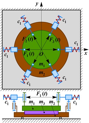
a)
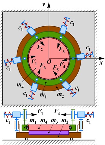
b)
2.2. Substantiating the idea of generating plane oscillations of the working member
During the operation of the considered oscillatory system of the lapping-polishing machine, the reciprocating motion (circular oscillations) of the working member can cause the formation of grooves (notches) and increases the intensity of its wear. This leads to the necessity of dressing the working member more often. In order to improve the quality and efficiency of the vibratory finishing process, it is proposed to slowly rotate the working member around the vertical axis passing through its mass center. In such a case, the working member performs plane (plane-parallel) oscillations: its central point moves in a circle, and all the other points of the working surface move in the same circle and slowly rotate around the point .
The simplified dynamic diagram of the improved vibratory lapping-polishing machine is presented in Fig. 1(b). Unlike the previous design, in the improved one, the working member (mass ) is placed inside the carrying disk (mass ) with the possibility of rotating around its central point . The special rubber disk is placed between the upper carrier and the working member to generate its plane oscillations (reciprocating motion with the center and rotating around this point). In such a case, the electromagnets are hinged to the lower carrier (mass ), and their movable plungers (armatures) are spring-loaded and joined with the upper carrying disk in a circle. The directions of the disturbing electromagnetic forces , , , , , and are inclined at the angle to the chord lines connecting the radially located hinges of the armatures (plungers). The radial components of the mentioned forces generate the reciprocating motion (circular oscillations) of the working member similar to the one obtained in the previous machine design (see Fig. 1(a)). The tangential components of the disturbing forces generate the rotation of the working member around its central point due to occurring of the dry friction between the rubber disk and the working member.
In order to describe the central point positions of the upper carrier (mass ) and the lower carried with the workpiece being treated (masses and ) in the inertial frame , the corresponding generalized coordinated , , , are used. The angular positions of the lower and upper carriers are defined by the angles and , respectively. The plane oscillations of the working member (mass ) can be described by the position of its central point – , (neglecting the deformation of the rubber disk), and by the angle defining its rotation around the point . The following simplified mathematical model describes the motion conditions of the considered three-mass oscillatory system:
where the radial and tangential components of the excitation forces are as follows: , , , , , ; the radial and tangential components of the stiffness coefficients projected on the and axes are the following: , , , ; the radial components of the viscous friction coefficient are as follows: ; is the radius of the working member; is the radius of mounting the hinges that connect the upper carrier with the plunders (armatures) of the electromagnets (solenoids); , , , are the moments of inertia of the upper carrier, lower carrier, workpiece, and working member, respectively; is the coefficient of dry friction occurring between the rubber disk and the working member.
3. Results and discussion
3.1. Numerical modeling of the working member reciprocating motion
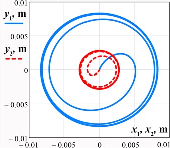
Let us perform the numerical modeling of the working member reciprocating motion by solving the system of differential equations Eq. (1) in the MathCad software using the Runge-Kutta methods. The following input parameters are used [14]: 0.42 kg, 0.5 kg, 0.75 kg, 100.5 rad/s (16 Hz), 4 N, 3700 N/m, and 20 (N∙s)/m. The results of numerical modeling – time dependencies of the working member and lower carrier displacements along horizontal and vertical axes, and their mass center paths (trajectories) – are shown in Fig. 2(a) and Fig. 2(b), respectively. Horizontal and vertical amplitudes of the working member reach 8 mm, and of the lower carrier – 2.7 mm. The transient operation mode lasts about 0.2 s. Considering the simulated trajectory (path) of the working member and the lower carrier, it can be concluded that the initially stated idea about their reciprocating motion (translational (circular) oscillations) is satisfied: the working member moves in a circle of the radius 8 mm, while the lower carrier with the part being treated has a circular path of the radius 2.7 mm. Therefore, the proposed machine design allows for providing a uniform speed and the same motion direction at each point of the working surface. In such a case, the improved accuracy and efficiency of the vibratory finishing treatment can be reached.
Fig. 2Results of numerical modeling of the working member and lower carrier oscillations: a) time response curves; b) motion path (trajectory)
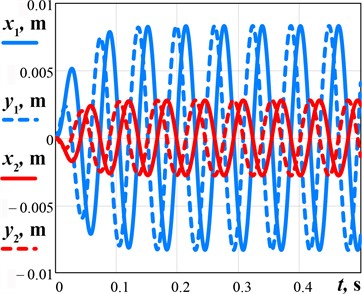
a)
b)
3.2. Generating the plane oscillations of the lap (polisher, glazer)
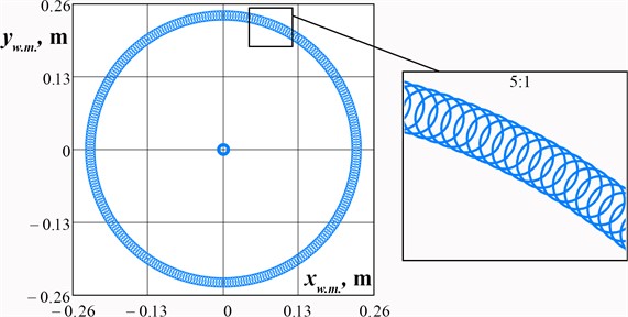
Considering the case when 15°, 0.2 m, 0.23 m, 0.6, 0.004 kg∙m2, 0.014 kg∙m2, 0.018 kg∙m2, 0.009 kg∙m2, let us perform numerical modeling of the working member oscillations in the MathCad software using the system of differential Eq. (2). The obtained results are shown in Fig. 3. The center point of the working member performs the reciprocating motion (translational oscillations) in a circle of the radius 8 mm, while the peripheral (satellite) points move in similar paths and slowly rotate around the center of the working member. This proves the initially stated hypothesis. In distinction to the previous machine design, the improved one can provide the plane (plane-parallel) oscillations of the working member.
Fig. 3Results of numerical modeling of the working member oscillations of the improved machine
4. Conclusions
The paper is devoted to analyzing the possibilities of generating the reciprocating motion (circular (translational) oscillations) and plane (plane-parallel) oscillations of the working member of a vibratory lapping-polishing machine. Two basic designs of the machine’s oscillatory systems are considered, and the corresponding mathematical models describing their motion conditions are derived. The numerical modeling of the working member oscillations is carried out in the MathCad software with the help of the Runge-Kutta methods. Considering the initial design of the machine, each point of the working member moves in a circle of a radius 8 mm, while the lower carrier with the part being treated has a circular path of a radius 2.7 mm. The improved machine allows the working member to perform plane oscillations where its center point is under the conditions of the reciprocating motion (translational oscillations) in a circle of the radius 8 mm, and the peripheral (satellite) points move in similar paths and slowly rotate around the center of the working member. The obtained results can be used for improving the accuracy of vibratory lapping-polishing machines.
References
-
R. Guminilovych, P. Shapoval, I. Yatchyshyn, and S. Shapoval, “Modeling of chemical surface deposition (CSD) of CdS and CdSe semiconductor thin films,” Chemistry and Chemical Technology, Vol. 9, No. 3, pp. 287–292, Sep. 2015, https://doi.org/10.23939/chcht09.03.287
-
V. Borovets, O. Lanets, V. Korendiy, and P. Dmyterko, “Volumetric vibration treatment of machine parts fixed in rotary devices,” in Lecture Notes in Mechanical Engineering, pp. 373–383, 2021, https://doi.org/10.1007/978-3-030-68014-5_37
-
J. Kundrák, M. Morgan, A. V. Mitsyk, V. A. Fedorovich, and A. I. Grabchenko, “Mathematical simulation of the vibration treatment of parts in a liquefied abrasive working medium,” The International Journal of Advanced Manufacturing Technology, Vol. 120, No. 7-8, pp. 5377–5398, Jun. 2022, https://doi.org/10.1007/s00170-022-08843-8
-
A. Mitsyk, V. Fedorovich, and A. Grabchenko, “Wave nature of the abrasive granules action on the surface of parts during vibration processing,” in Lecture Notes in Mechanical Engineering, pp. 176–189, 2023, https://doi.org/10.1007/978-3-031-16651-8_17
-
B. Pan, R. Kang, X. Zhu, D. Du, W. Huang, and J. Guo, “Formation mechanism of concave and convex surface shapes in double-sided lapping,” Journal of Materials Processing Technology, Vol. 309, p. 117749, Nov. 2022, https://doi.org/10.1016/j.jmatprotec.2022.117749
-
J. Guo et al., “Stress-induced deformation of thin copper substrate in double-sided lapping,” Chinese Journal of Mechanical Engineering, Vol. 36, No. 1, pp. 1–10, Feb. 2023, https://doi.org/10.1186/s10033-022-00824-y
-
L. Yang, X. Guo, R. Kang, X. Zhu, and Y. Jia, “Effect of kinematic parameters considering workpiece rotation on surface quality in YAG double-sided planetary lapping with the trajectory method,” The International Journal of Advanced Manufacturing Technology, Vol. 123, No. 7-8, pp. 2679–2690, Dec. 2022, https://doi.org/10.1007/s00170-022-10288-y
-
C. Micallef, K. Walton, Y. Zhuk, and A. I. Aria, “Surface finishing and residual stress improvement of chemical vapour deposited tungsten carbide hard coatings by vibratory polishing,” Surface and Coatings Technology, Vol. 439, p. 12844, 2022, https://doi.org/10.1016/j.surfcoat.2022.128447.https://doi.org/10.1155/2020/8015465
-
Z. Chen, D. Wen, J. Lu, J. Yang, and H. Qi, “Surface quality improvement by using a novel driving system design in single-side planetary abrasive lapping,” Materials, Vol. 14, No. 7, p. 1691, Mar. 2021, https://doi.org/10.3390/ma14071691
-
Z. Geng, P. Zhou, L. Meng, Y. Yan, and D. Guo, “Prediction of surface profile evolution of workpiece and lapping plate in lapping process,” Journal of Manufacturing Science and Engineering, Vol. 144, No. 8, p. 08100, Aug. 2022, https://doi.org/10.1115/1.4053279
-
T. Deaconescu and A. Deaconescu, “Developing an analytical model and computing tool for optimizing lapping operations of flat objects made of alloyed steels,” Materials, Vol. 13, No. 6, p. 1343, Mar. 2020, https://doi.org/10.3390/ma13061343
-
L. Zhao et al., “A real-time dressing method for metal lapping pads based on the thermal deformation effect,” The International Journal of Advanced Manufacturing Technology, Vol. 120, No. 1-2, pp. 945–958, May 2022, https://doi.org/10.1007/s00170-022-08869-y
-
V. Korendiy, V. Zakharov, V. Gurey, P. Dmyterko, I. Novitskyi, and O. Havrylchenko, “Modelling the operation of vibratory machine for single-sided lapping of flat surfaces,” Vibroengineering PROCEDIA, Vol. 38, pp. 1–6, Jun. 2021, https://doi.org/10.21595/vp.2021.22001
-
V. Korendiy, O. Kachur, V. Zakharov, and I. Kuzio, “Studying the dynamics of a vibratory finishing machine providing the single-sided lapping and polishing of flat surfaces,” Engineering Proceedings, Vol. 24, No. 1, Sep. 2022, https://doi.org/10.3390/iecma2022-12898
-
V. Korendiy, O. Kachur, V. Zakharov, I. Kuzio, O. Havrylchenko, and T. Hurey, “Dynamics and control of vibratory finishing machine with translational motion of lapping-polishing plates,” Vibroengineering PROCEDIA, Vol. 44, pp. 8–14, Aug. 2022, https://doi.org/10.21595/vp.2022.22842
-
V. Korendiy, O. Kachur, V. Zakharov, I. Kuzio, I. Hurey, and R. Predko, “Experimental study of the lap motion trajectory of vibratory finishing machine,” Vibroengineering PROCEDIA, Vol. 46, pp. 1–7, Nov. 2022, https://doi.org/10.21595/vp.2022.23002
About this article

The authors have not disclosed any funding.
The datasets generated during and/or analyzed during the current study are available from the corresponding author on reasonable request.
The authors declare that they have no conflict of interest.
