Abstract
The presented research continues the authors’ previous investigations on the dynamics of a wheeled vibration-driven robot. The main purpose of this paper consists in conducting the experimental studies of the robot motion conditions. The methodology of research is divided into three basic stages: designing the 3D-model of the robot in the SolidWorks software and implementing its experimental prototype; experimental studying the motion conditions and carrying out the corresponding measurements; analyzing the obtained results and forming the conclusions. The main findings (results) are presented in the form of time response curves of the basic kinematic characteristics of the robot motion: displacements, velocities, and accelerations of the robot’s wheeled platform and of the disturbing (impact) body. The novelty of this research consists in substantiating the possibilities of applying the vibro-impact working regimes to improve the kinematic characteristics and operational efficiency of the wheeled vibration-driven robot. The obtained results can be profitably used by designers and researchers of mobile locomotion systems, particularly those for inspecting the pipelines.
Highlights
- The 3D-model of the wheeled vibration-driven robot is designed in the SolidWorks software and implemented as an experimental prototype.
- The experimental investigations of the robot motion conditions are performed and the corresponding measurements are carried out.
- The results are presented as time dependencies of the robot’s kinematic characteristics: displacements, velocities, and accelerations of the robot’s wheeled platform and the disturbing (impact) body.
- The possibilities of applying the vibro-impact working regimes to improve the kinematic characteristics and operational efficiency of the wheeled vibration-driven robot are substantiated.
1. Introduction
Vibration-driven locomotion systems are of significant interest among scientists and researchers all over the world. Numerous research papers are dedicated to studying the dynamics, operational conditions, control systems, and parametric optimization of mobile robots driven by various vibratory actuators. Let us review some of the publications dealing with vibration-driven locomotion systems. The double-mass capsule-type system actuated by a harmonically disturbed internal mass is studied in [1]. The experimental prototype of a similar system has been investigated in [2]. Several enhanced designs of the single-module vibration-driven capsules are thoroughly analyzed in [3]. The paper [4] considers the problems of optimizing the parameters of vibratory robots in order to improve their locomotion performance. In [5], the authors studied the influence of various friction types on the dynamic behavior of the vibro-impact locomotion system. Similar investigations with numerous experimental data are presented in [6]. The paper [7] is dedicated to the locomotion speed optimization problems and to the analysis of the reliability issues of the self-propelled capsule-type robot. The possibilities of implementing the mobile vibratory robots for inspecting the pipelines are considered in [8]. Similar research dealing with the dynamic behavior and parameters optimization problems of the self-propelled one-way-moving robot is conducted in [9].
In distinction from the sliding locomotion system, there is a large number of publications dedicated to the wheeled robots driven by various vibratory actuators. In particular, the paper [10] presents the results of experimental investigations of the vibration-driven robot dynamic characteristics. Theoretical studies and numerical modeling of motion conditions of the same robot are conducted in [11] and [12]. The present research continues the authors’ previous investigations on the dynamics of the wheeled vibration-driven robot, particularly those published in [13]-[15]. The paper [13] considers the general case of providing the translational locomotion of the vibration-driven system able to slide along a rough horizontal surface and equipped with a twin crank-type exciter. In [14], the theoretical investigations of motion conditions of the wheeled vibratory robot are carried out. The paper [15] is dedicated to the computer simulation of the wheeled robot dynamics performed with the help of the applied software (SolidWorks, MapleSim). The main purpose of this paper is to conduct the experimental studies of the robot motion conditions. The novelty of this research consists in substantiating the possibilities of applying the vibro-impact working regimes to improve the kinematic characteristics and operational efficiency of the wheeled vibration-driven robot.
2. Research methodology
2.1. General design of the wheeled vibro-impact robot developed in SolidWorks software
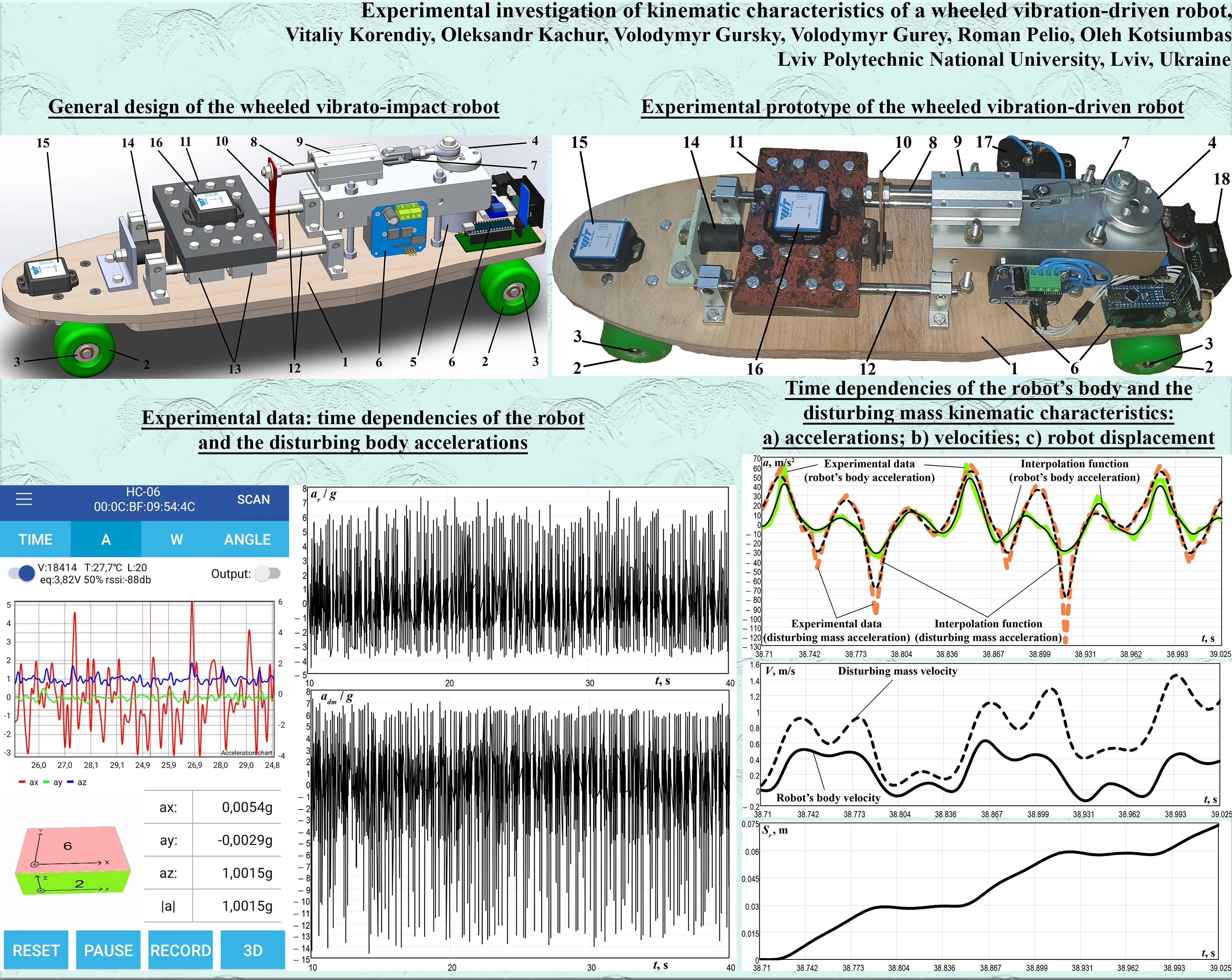
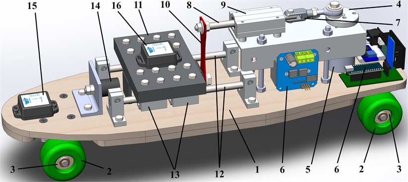
The 3D-model of the wheeled vibration-driven robot was designed in the SolidWorks software (see Fig. 1). The robot’s body 1 is based on the wheeled supports 2. The wheels are allowed to rotate counterclockwise due to applying the roller-type overrunning (free-wheel) clutches 3 that engage in one direction and free-wheel in the other one. The eccentric (crank) 4 is driven by the DC motor 5 controlled by the electronic system 6. With the help of the connecting rod 7, the rotation of the eccentric 4 is transformed to the translational motion of the slider (sliding rod) 8 supported by the linear (guide, pilot) bearing 9. The latter is fixed on the robot’s body 1. The slider 8 is connected to the flat spring 10 actuating the impact (disturbing) body 11. The latter can slide along the guides (guide rods) 12 due to the application of the linear bearings 13. The translational oscillations of the impact body 11 cause the displacements of the robot’s body mass center, and generate the forward step-wise motion of the wheeled platform 1 restricted from the backward motion by the overrunning (free-wheel) clutches 3. In order to increase the robot locomotion speed and improve its operational efficiency, it is proposed to use the vibro-impact working regimes. The latter take place when the disturbing body 11 periodically impacts the rubber damper 14 connected to the wheeled platform 1. In order to carry out experimental investigations on the robot dynamic behavior, the accelerometers 15 and 16 are fixed to the robot’s body and to the disturbing body, respectively.
Fig. 1General design of the wheeled vibrato-impact robot
2.2. Engineering prototype of the robot and experimental technique
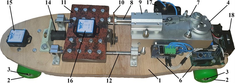
The experimental prototype of the wheeled vibro-impact robot (Fig. 2) has been developed at the Vibroengineering laboratory of Lviv Polytechnic National University. All the position numbers referenced in Fig. 2 correspond to the ones used in the 3D-model (Fig. 1). The experimental prototype is additionally equipped with the constant-voltage source 17 (of the nominal value equal to 15 V), and the voltmeter 18. All the control functions are performed remotely from the mobile phone using the Bluetooth technology. The control system 6 is based on the Arduino hardware and software. The Bluetooth sensors WT901BLECL manufactured by the WitMotion company (see positions 15 and 16 in Fig. 2) allow for simultaneous measuring of the robot and the impact body accelerations at the retrieval rate of 200 Hz and the bandwidth up to 256 Hz. The driving DC motor equipped with the planetary-type gearbox provides the controllable rotation frequency of the eccentric 4 in the range of 0,…, 1000 rpm (0,…, 16.7 Hz). The mass of the whole robot is equal to 3.8 kg, and of the impact body – 1.6 kg.
Fig. 2Experimental prototype of the wheeled vibration-driven robot
The experimental technique consists of two basic stages: studying the motion conditions and making the corresponding measurements; analyzing the obtained results and forming the conclusions. In the first stage, the robot is set into motion at a certain forced frequency controlled by the voltage value applied to the DC motor. The accelerometers’ data is written by the WitMotion application and stored in the memory of the mobile phone. The obtained results are presented in the form of time dependencies of the corresponding accelerations relative to the free-fall (gravity) acceleration . Therefore, the absolute values of these accelerations can be easily calculated. Then, using the MathCad software, the numerical integration of the obtained results is to be performed in order to obtain the time response curves of the robot and the disturbing mass velocities and displacements. The mentioned experimental investigations can be carried out several times for different values of the forced frequency, disturbing mass, spring stiffness, impact gap, and eccentricity of the crank-type vibration exciter.
3. Results and discussion
3.1. Experimental results
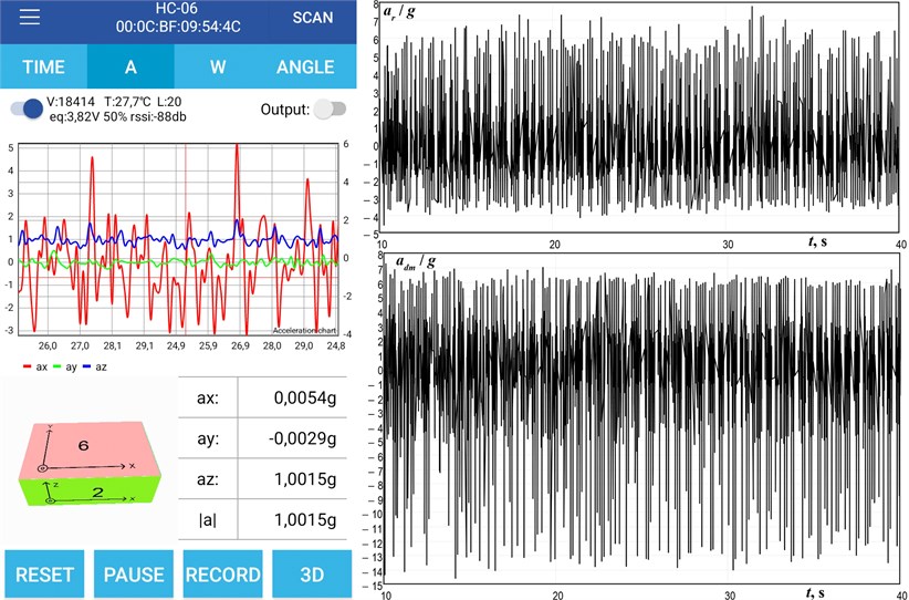
The experimental data has been recorded by the WitMotion application (see Fig. 3) and transformed into the numerical format in the form of the Excel table. The sensor retrieval rate is about 200 Hz; therefore, the time interval of the measured data is approximately 0.005 s. The experimentally obtained time dependencies of the robot’s body and the disturbing mass accelerations are presented in Fig. 3. The maximal values of the wheeled platform acceleration reach 7 (68.7 m/s2), while its deceleration doesn’t exceed 4 (39.2 m/s2). The mentioned parameters of the disturbing mass are equal to 7 (68.7 m/s2) and 14 (137.3 m/s2), respectively. The periodical peaks of the robot’s body and the impact mass accelerations are observed at the same time moments and correspond to the forced frequency of about 8 Hz. This allows for drawing a preliminary conclusion about the vibro-impact motion conditions.
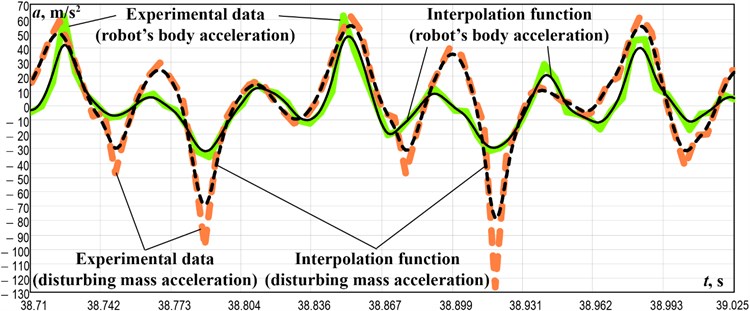
The obtained experimental results have been thoroughly analyzed, and the entire time interval of the carried-out measurements has been divided into several subintervals. The latter take into account the stable indications of the measuring equipment characterized by the constant time steps of 0.005 s. One of such intervals takes place within 38.710,…, 39.025 s (Fig. 4). The numerical interpolation algorithms integrated in the MathCad software allow for quick processing of the discrete experimental data, and generating the continuous (polynomial) acceleration functions with the prescribed accuracy. The examples of such functions are plotted in Fig. 4(a), where the green and orange curves present the experimental data obtained from the robot’s body and the disturbing mass accelerometers (positions 15 and 16 in Fig. 1), and the corresponding black curves interpolate this data in the form of the polynomial function.
Fig. 3Experimental data: time dependencies of the robot and the disturbing body accelerations
3.2. Analyzing the robot kinematic characteristics
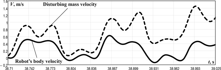
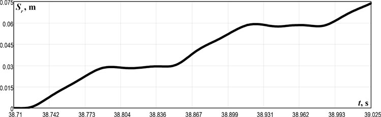
In order to analyze the other kinematic characteristics of the robot’s body motion, it is necessary to perform the numerical integration of the obtained experimental data of the wheeled platform acceleration using the applied software, particularly PTC MathCad. The corresponding results presenting the time dependencies of the robot velocities and displacements are shown in Fig. 4. The robot’s body velocity periodically reaches its maximal values of about 0.6 m/s, while its minimal values fall to –0.1 m/s (Fig. 4 (b)). The disturbing mass velocity periodically changes in the range of 0,…, 1.4 m/s. The general character of the robot motion corresponds to the one previously modeled and simulated in the papers [14] and [15]. The wheeled platform performs the step-wise motion and travels a distance of about 74 mm during the time interval of 0.315 s (within 38.710,…, 39.025 s). Single-step duration is about 0.12,…, 0.13 s, and the distance traveled by the robot during one step is almost 0.03 m (Fig. 4(c)). Therefore, it can be concluded that the robot average speed is approximately 0.23 m/s. The same results can be obtained when analyzing the interpolated time dependencies of the robot velocity in the MathCad software using the following “averaging” formula:
where is the average value of the robot’s wheeled platform velocity; is the forced frequency provided by the controllable driving motor shaft rotation ( ≈ 8 Hz); denotes the starting moment of time for carrying out the numerical calculations; is the continuous function of the robot’s body velocity numerically integrated in the MathCad software using the interpolated polynomial function of the robot acceleration (see Fig. 4(a) and (b)).
Fig. 4Time dependencies of the robot’s body and the disturbing mass kinematic characteristics: a) accelerations; b) velocities; c) wheeled platform displacement
a)
b)
c)
4. Conclusions
The paper focuses on the experimental investigation of the wheeled vibro-impact robot motion conditions. The robot’s 3D-model is designed in the SolidWorks software (Fig. 1) and implemented in practice as an experimental prototype (Fig. 2) at the Vibroengineering laboratory of Lviv Polytechnic National University. The experimental results show that the maximal values of the wheeled platform acceleration reach 7 (68.7 m/s2), while its deceleration doesn’t exceed 4 (39.2 m/s2) (Fig. 3 and 4(a)). The robot’s body velocity periodically reaches its maximal values of about 0.6 m/s, while its minimal values fall to –0.1 m/s (Fig. 4 (b)). The wheeled platform performs the step-wise motion and travels a distance of about 74 mm during the time interval of 0.315 s (within 38.710,…, 39.025 s). Single-step duration is about 0.12,…, 0.13 s, and the distance traveled by the robot during one step is almost 0.03 m (Fig. 4 (c)). Therefore, the robot average speed is approximately 0.23 m/s.
The obtained results can be profitably used by designers and researchers of mobile locomotion systems, particularly those for inspecting and cleaning the pipelines, tubes, tunnels, etc. Further investigations on the subject of the paper can be devoted to analyzing the robot’s design, inertial and stiffness parameters (eccentricity value (crank length), disturbing body mass, initial impact gap, spring stiffness, etc.) on its translational velocity and operational efficiency.
References
-
Y. Liu, M. Wiercigroch, E. Pavlovskaia, and H. Yu, “Modelling of a vibro-impact capsule system,” International Journal of Mechanical Sciences, Vol. 66, pp. 2–11, Jan. 2013, https://doi.org/10.1016/j.ijmecsci.2012.09.012
-
Y. Yan, Y. Liu, J. Páez Chávez, F. Zonta, and A. Yusupov, “Proof-of-concept prototype development of the self-propelled capsule system for pipeline inspection,” Meccanica, Vol. 53, No. 8, pp. 1997–2012, Jun. 2018, https://doi.org/10.1007/s11012-017-0801-3
-
J. Xu and H. Fang, “Improving performance: recent progress on vibration-driven locomotion systems,” Nonlinear Dynamics, Vol. 98, No. 4, pp. 2651–2669, Dec. 2019, https://doi.org/10.1007/s11071-019-04982-y
-
B. Diao, X. Zhang, H. Fang, and J. Xu, “Bi-objective optimization for improving the locomotion performance of the vibration-driven robot,” Archive of Applied Mechanics, Vol. 91, No. 5, pp. 2073–2088, May 2021, https://doi.org/10.1007/s00419-020-01870-5
-
K.-T. Nguyen, N.-T. La, K.-T. Ho, Q.-H. Ngo, N.-H. Chu, and V.-D. Nguyen, “The effect of friction on the vibro-impact locomotion system: modeling and dynamic response,” Meccanica, Vol. 56, No. 8, pp. 2121–2137, Aug. 2021, https://doi.org/10.1007/s11012-021-01348-w
-
V.-D. Nguyen, K.-T. Ho, N.-T. La, Q.-H. Ngo, and K.-T. Nguyen, “An experimental study on the self-propelled locomotion system with anisotropic friction,” in Lecture Notes in Mechanical Engineering, Singapore: Springer Singapore, 2022, pp. 537–545, https://doi.org/10.1007/978-981-16-3239-6_40
-
M. Liao, J. Zhang, Y. Liu, and D. Zhu, “Speed optimisation and reliability analysis of a self-propelled capsule robot moving in an uncertain frictional environment,” International Journal of Mechanical Sciences, Vol. 221, p. 107156, May 2022, https://doi.org/10.1016/j.ijmecsci.2022.107156
-
K. Ragulskis, M. Bogdevičius, and V. Mištinas, “Behaviour of dynamic processes in self-exciting vibration of a pipe robot,” Journal of Vibroengineering, Vol. 10, No. 3, pp. 397–399, Sep. 2008.
-
K. Ragulskis et al., “Investigation of dynamics of a pipe robot with vibrational drive and unsymmetric with respect to the direction of velocity of motion dissipative forces,” Agricultural Engineering, Vol. 52, pp. 1–6, Feb. 2021, https://doi.org/10.15544/ageng.2020.52.1
-
I. A. Loukanov and S. P. Stoyanov, “Experimental determination of dynamic characteristics of a vibration-driven robot,” IOSR Journal of Mechanical and Civil Engineering, Vol. 12, No. 4, pp. 62–73, 2015, https://doi.org/10.9790/1684-12426273
-
I. A. Loukanov, V. G. Vitliemov, and I. V Ivanov, “Dynamics of a mobile mechanical system with vibration propulsion (VibroBot),” International Journal of Engineering Research and General Science, Vol. 4, No. 6, pp. 2320–9364, Jul. 2016.
-
I. A. Loukanov, V. G. Vitliemov, and I. V. Ivanov, “Dynamics of a vibration-driven one-way moving wheeled robot,” IOSR Journal of Mechanical and Civil Engineering, Vol. 13, No. 3, pp. 14–22, 2016, https://doi.org/10.9790/1684-1303051422
-
V. Korendiy, V. Gursky, O. Kachur, V. Gurey, O. Havrylchenko, and O. Kotsiumbas, “Mathematical modeling of forced oscillations of semidefinite vibro-impact system sliding along rough horizontal surface,” Vibroengineering Procedia, Vol. 39, pp. 164–169, Dec. 2021, https://doi.org/10.21595/vp.2021.22298
-
V. Korendiy, V. Gursky, O. Kachur, P. Dmyterko, O. Kotsiumbas, and O. Havrylchenko, “Mathematical model and motion analysis of a wheeled vibro-impact locomotion system,” Vibroengineering PROCEDIA, Vol. 41, pp. 77–83, Apr. 2022, https://doi.org/10.21595/vp.2022.22422
-
V. Korendiy et al., “Motion simulation and impact gap verification of a wheeled vibration-driven robot for pipelines inspection,” Vibroengineering Procedia, Vol. 41, pp. 1–6, Apr. 2022, https://doi.org/10.21595/vp.2022.22521
About this article

