Abstract
The steel-concrete joint, serving as a transition zone between the steel and concrete girders, is the key component for transferring force among the hybrid girder systems. Despite the expected smooth transition of stiffness, high strength, easy fabrication, and verified static resistance, the structural performance of the steel-concrete joint under service loadings in a long-term period remains unclear. In this study, a FE model of a 1/2 steel-concrete joint from a real bridge is established to explore the long-term performance of the structure. Numerical results show that the minimal relative slip between the concrete infill and steel girder indicated the reliable capability of the steel-concrete joint, and the maximum concrete and steel stresses are 8.8 MPa and 192.8 MPa, respectively, which are far less than the material’s ultimate strength. The outcomes of this study can serve as a reference for analyzing the long-term performance of steel-concrete joints in hybrid girder bridges.
Highlights
- Structural behavior of steel-concrete joint was studied by numerical model.
- The influence of creep and shrinkage from concrete infill on local stress of the joints was discussed.
- Long-term performance of steel-concrete joints in hybrid girder was analyzed.
1. Introduction
Steel-concrete hybrid girders, using steel and prestressed concrete (PC) girders along the longitudinal bridge direction, are very competitive in designing large-span bridges. Particularly, the use of a steel girder in the middle span can significantly increase the maximum span and minimize the number of piers, while the adoption of a PC girder in the side span can effectively anchor the long middle span and improve bridge stiffness [1]. To achieve these merits, the design and detailing of steel-concrete joints between the steel and concrete girders become critical. The ideal steel-concrete joint for a hybrid girder should smoothly transfer internal force and stiffness and has high strength, good durability, and good fatigue resistance. In practice, steel-concrete joints of concrete-filled steel cells with bearing plates and mechanic connectors are widely used in recently constructed hybrid girder bridges. According to the arrangement of bearing plates, the joint can be classified as the joint with the front bearing plate, the one with the rear bearing plate, and the one with double bearing plates. Along with the shearing effect provided by the mechanic connectors, the local direct contact effect between bearing plates and concrete infill transfers forces between the PC and steel girders.
In literature, model tests on steel-concrete joints usually originated from real hybrid girder bridges. By using a scale ratio of 1:2, Zhang and Wu [2] and Li et al. [3] investigated the load-displacement curve, load-strain responses, and relative slip of steel-concrete joint subjected to various load combinations. The experimental results indicated that up to 75% of the axial loads at the joint zone were transferred by the local contact effect of bearing plates, while the rest loads flowed into steel cells and were mainly dispersed by shear connectors. He et al. [4] studied the structural response of steel-concrete joints under axial, bending, and twist forces. The experimental results revealed that axial and bending forces mostly governed stresses in steel-concrete joints. Numerical studies have also been established to examine the behavior of steel-concrete joints further [5, 6].
As mentioned earlier, steel-concrete joints play vital roles in dispersing internal forces from PC girders to steel girders. However, due to the evitable occurrence of concrete shrinkage and creep inside steel cells, the load transferred at the joint part would vary with the servicing period. Existing studies seldom focus on the load transition in steel-concrete joints after the bridge has been operating for a long time. To explore possible unsafe stress variation caused by shrinkage and creep of concrete, it is particularly interesting to examine the long-term performance of steel-concrete joints of hybrid girder bridges.
This paper focuses on the structural performance of steel-concrete joints in hybrid girder bridges under a combined effect of external load in servicing period. Based on the configurations of a hybrid girder bridge in China, a full-scale FE solid model of a 1/2 steel-concrete joint was established to simulate the long-term structural behavior. The numerical results including the displacement and strains of the steel-concrete joint were presented and discussed. The outcomes of this study provided a useful reference for the long-term performance of steel-concrete joints in hybrid girder bridges.
2. Numerical work
2.1. Prototype bridge descriptions
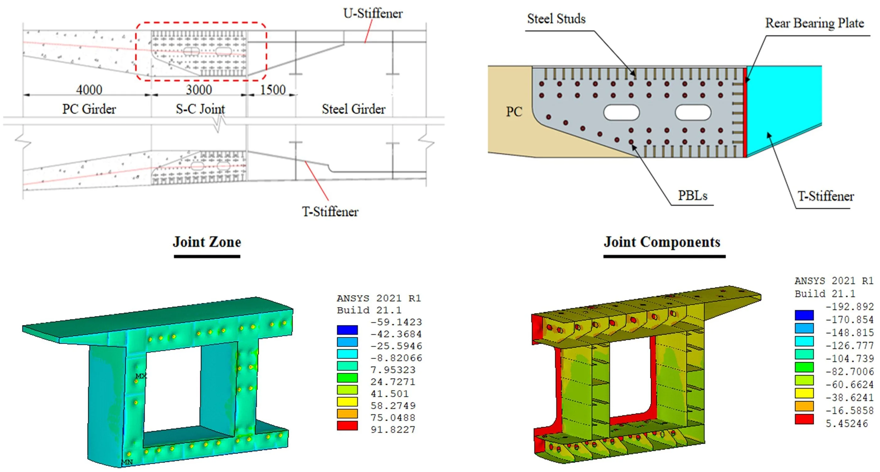
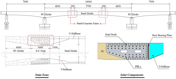
The hybrid girder bridge under construction is located in Guangdong province, China. Fig. 1 shows the main configurations of the background bridge, together with the details of the steel-concrete joint segment. The hybrid girder in the prototype bridge consists of the steel girder at the midspan, two steel-concrete joints, and two PC girders at the side spans. The steel-concrete joint was composed of several concrete-filled steel cells accompanied by rear bearing plates and shear connectors, and the steel cells were filled with C55 concrete. As can be seen in Fig. 1, the joint segment is equipped with rear bearing plates, performed rib (PBL) connectors, and headed studs.
The thickness of the rear steel plate is 50.0 mm. The diameters of perforated plate holes and transverse rebars are 60.0 mm and 25.0 mm, respectively. The diameter and shank length of steel studs are 22.0 mm and 150.0 mm, respectively. The compressive strength and elasticity modulus of C55 is 60.4 MPa and 35.7 GPa, respectively. Q345qE grade steel (with a nominal yield strength of 345.0 MPa) and HRB335 steel rebar (with a nominal yield strength of 335.0 MPa) are adopted for the steel plates and reinforcements at the joint zone. Prestressed tendons with the tensile strength of 1,860.0 MPa anchoring at the rear bearing plate are stressed at 1,395.0 MPa.
Fig. 1Schematics of the prototype bridge
2.2. Finite element model
2.2.1. Elements and material modeling
For ease of calculation, the FE solid model of 1/2 steel-concrete joint is established by the static analysis module of the Ansys software. In the established solid model, the solid65 element is used for the concrete girder, the shell63 element is used for the steel girder, and the combin14 element is used for the steel studs and PBL connectors. Table 1 summarizes the material properties defined in the FE solid model.
Table 1Summary of material properties
Item | Elastic modulus (MPa) | Density (kN/m3) | Poisson’s ratio |
Concrete | 3.57×10⁴ | 25.0 | 0.2 |
Steel | 2.10×10⁵ | 78.5 | 0.3 |
The main objective of this work is to explore the structural response of the steel-concrete joint after one year under the action of 2.0P. The shrinkage and creep effects of concrete members significantly affect the structural response and are considered as follows [7].
Shrinkage effect.
The expressions for shrinkage strain of concrete are expressed as:
where: is shrinkage strain of concrete at the age from to ; is the age of the concrete at the time considered for the calculation (); is the age of the concrete at the time start of shrinkage (), :
where: is the theoretical thickness of the component (mm); ; is the cross-sectional area of the component (mm2); is the perimeter length of the component in contact with the atmosphere (mm); 100 mm:
where: is the average compressive strength for concrete at 28 (MPa); ; is the coefficient related to the type of cement for the current study, 5; = 70 %; 100 %.
Creep effect.
The expressions for the creep coefficient of concrete are expressed as follows:
where: is the creep coefficient of concrete; is the nominal creep coefficient of concrete; is the growth coefficient of concrete creep with time. is the age of the concrete at the time starting creep ():
where: is relative humidity influence factor; is concrete strength influence factor; is the age effect factor of concrete. Other symbols have the same meaning as mentioned early.
Combining the above expressions, the cooling method is used to simulate the shrinkage effect, and the creep criterion is adopted to analyze the creep effect.
2.2.2. Displacement and load boundaries
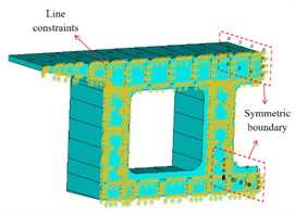
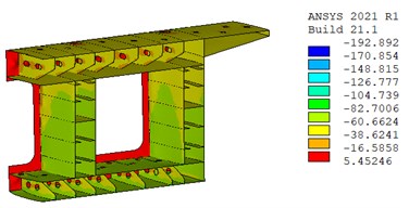
Fig. 2 presents the established FE solid model. As can be seen, the supporting effect of the T-stiffeners in the steel girder is simulated by simplified line constraints. Full restraint is applied to the rear bearing plate and the contacted concrete surface. The nodes at the ends of the shear connectors (e.g., steel studs and PBL connectors) are coupled to the concrete and steel girder, respectively. Symmetric boundary conditions are imposed at the axis of symmetry of the joint.
A system calculation of the bridge using the Midas Civil computer agency was performed to determine the most critical load combination for the joint. The calculation results of loads under the most critical combination are summarized in Table 2. It is observed that the shear force at the joint zone is minuscule and could be neglected as compared with the other forces, while the axial and bending forces are comparatively large and should be considered for the model. Accordingly, only axial and bending loads (2.0P) were applied to the model.
Fig. 21/2 FE solid model of steel-concrete joint
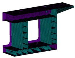
a) Steel grider part
b) Concrete infill part
c) Displacement boundaries
Table 2Design Loads of the steel-concrete joint under the most critical load combination
Item | Axial force (kN) | Bending moment () | Shear force (kN) |
Real bridge | –267,164 | –105,666 | 11,263 |
1/2 FE solid model | –267,164 | –105,666 | 0 |
2.3. FE results and discussion
2.3.1. Displacement distribution
Fig. 3 shows the displacement distribution of steel-concrete joint after one year under 2.0P. As can be seen, the displacement varies along the length of the girder, and the displacement of the zone away from the rear bearing plate is larger, indicating the joint has a significant dispersion effect on the axial force. Positive displacement occurs in the local area around prestressed tendons. Due to the influence of the bending moment, the bottom slab shows a maximum displacement of -0.98 mm compared to the top slab of the joint. The similar displacement distribution of concrete infill and steel girder indicated no obvious slip between them, demonstrating the reliable capability of the steel-concrete joint in transferring force.
Fig. 3Displacement distribution of Steel-Concrete Joint after a year (unit: mm)
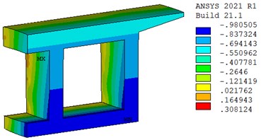
a) Displacement distribution in concrete infill part
b) Displacement distribution in steel grider part
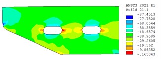
2.3.2. Stress distribution
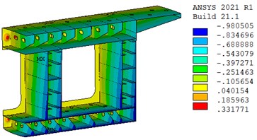
Fig. 4(a) and (b) show the stress distribution of the steel-concrete joint after one year under the action of 2.0P. It can be seen that in addition to the stress concentration at the local position around the prestressed tendons, the compressive stress of the concrete is about 8.8 MPa, and the maximum stress of the steel beam is 192.8 MPa, which is far less than the ultimate strength of the material. In addition, the stress distribution in steel girder and concrete infill also shows that the stress level of the bottom plate is higher than that of the top plate, which is in good agreement with the characteristics of displacement distribution.
Fig. 4Stress distribution of steel-concrete joint after a year (unit: MPa)
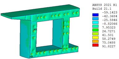
a) Stress distribution in concrete infill part
b) Stress distribution in steel grider part
c) Stress distribution in perforated web (top slab)
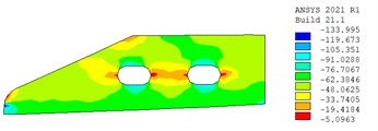
d) Stress distribution in perforated web (bottom slab)
Fig. 4(c) and (d) show the stress distribution in perforated webs. It is clear that the compressive stress is mainly distributed on the perforated webs, and the compressive stress level of the perforated webs at the bottom slab is higher than that at the top slab. Due to the minimal slip between the steel girder and concrete infill, no obvious stress concentration has been observed around the shear connectors (e.g., head studs and PBL connectors), while it has been observed on the long side of the grouted holes. Accordingly, the low-stress level demonstrates that the steel-concrete joint is serving in the elastic stage and still has a large safety margin.
3. Conclusions
This paper investigated the long-term performance of hybrid girder bridges’ steel-concrete joints through numerical method. A full-scale FE model originating from a 1/2 steel-concrete joint of a real hybrid cable-stayed bridge is established to explore the joint’s displacement distribution and stress distribution after one year under the action of 2.0P.
1) The displacement distribution from the FE solid model indicates that little slip occurred between the steel girder and concrete infill. The stress distribution indicated the steel-concrete joint was working in its elastic behaving stage despite maintaining the load level of 2.0P for a year.
2) Minimal vertical displacement observed from the experiment demonstrates good bending stiffness of the steel-concrete joint in connecting the PC and steel girders. The load in steel bolts and the stress in concrete infill had slightly declined due to concrete’s shrinkage and creep effects and the relaxation of steel bolts in the long-term monitoring period.
References
-
J. Nie, Steel-Concrete Composite Bridges. (in Chinese), Beijing, China: China Communications Press Co., 2011.
-
Zhang Qi-Zhi and Wu Bao-Shi, “Model test study of steel and concrete joint section of Jiujiang Changjiang River Highway Bridge,” (in Chinese), Bridge Construction, No. 5, pp. 68–74, 2013.
-
Y. Li, Y. Liu, F. Wang, and F. Yang, “Load transfer mechanism of hybrid pylon joint with cells and bearing plates,” Advances in Civil Engineering, Vol. 2018, pp. 1–12, Dec. 2018, https://doi.org/10.1155/2018/6289721
-
S. He, G. Yang, W. Zhou, Q. Li, and Y. Dong, “Evaluation of shear lag effect in HSS-UHPC composite beams with perfobond strip connectors: experimental and numerical studies,” Journal of Constructional Steel Research, Vol. 194, p. 107312, Jul. 2022, https://doi.org/10.1016/j.jcsr.2022.107312
-
S. He, Q. Li, G. Yang, X. Zhou, and A. S. Mosallam, “Experimental study on flexural performance of HSS-UHPC composite beams with perfobond strip connectors,” Journal of Structural Engineering, Vol. 148, No. 6, p. 04022064, Jun. 2022, https://doi.org/10.1061/(asce)st.1943-541x.0003366
-
Y. Xu, S. He, P. Guan, A. S. Mosallam, J. Zeng, and Z. Wan, “Shear behavior of flexible-sleeve perfobond strip connectors: experimental and analytical studies,” Engineering Structures, Vol. 264, p. 114380, Aug. 2022, https://doi.org/10.1016/j.engstruct.2022.114380
-
“CEB-FIP model code1990 (MC90),” Thomas Telford, London, Comite Euro-International du Beton, 1990.
About this article

The authors express their sincere gratitude for the financial support provided by the Science and Technology Project of Guangzhou, China (Grant No. 202102020652).
The datasets generated during and/or analyzed during the current study are available from the corresponding author on reasonable request.
The authors declare that they have no conflict of interest.
