Abstract
Complex bridges will inevitably have cracks in operation. Dynamic characteristics with crack structures have been researched central issues. In the past, few researches were conducted from the whole structure of bridges with multi-cracks. In the meanwhile, related experimental research and systematic numerical simulation were lacking. In addition, researches on cracks seldom considered the high-order vibration characteristics of structures with multi-cracks. Aimed at this problem, this paper selected the whole bridge structure which was widely applied in engineering to study dynamic characteristics. For the concrete steel bridge with two cracks, this paper established finite element models for concrete steel beam and bridge with cracks under three different conditions and obtained vibration frequency and three order modes through simulation. Then, this paper analyzed and verified the correctness of numerical simulation result through experiment. Based on the verified model, this paper conducted a systematic analysis and summary, and obtained the following findings: The vibration frequency of concrete steel beams with cracks was obviously affected by cracks. The higher the order was, the greater the impact of cracks on frequency would be and the smaller the impact of cracks on the amplitude of modes would be. With the increased crack depth, the impact on the vibration frequency of concrete steel beams was more obvious. Additionally, crack distance also had some impacts on the dynamic characteristics of concrete steel beams. Numerical simulation model and method in this paper provided foundation and reference for continuing to analyze concrete steel beams with other crack forms or other structural forms. In the meanwhile, the three-dimensional analytical contour in this paper could help engineers to more intuitively understand and valuably apply the change rule of impact of crack depth and position on concrete steel beams.
1. Introduction
With the large-scale development of structures, some complex structures including gymnasiums, skyscrapers and long-span bridges have been faced with the damage accumulation of structures due to the action of cyclic loads.
Cracks are one of the most common damage of structures. When a structure is under the action of static or dynamic loads, a small crack may cause a serious damage to the structure. There are many similar situations in published reports. For example, an airplane exploded at the time of takeoff due to the crack of center tank in 1985, which caused serious casualties [1]. In 2004, the cantilever end of a bridge had some cracks due to overload, which led to the falling of the whole bridge deck [2]. Generally speaking, the damage of structures will usually change the physical properties of structures, like mass, damping and stuffiness and cause changes in the dynamic characteristics of structures [3]. Therefore, it is necessary to study the dynamic characteristics of cracks in order to monitor the impact of changes in the dynamic characteristics, confirm whether structures are damaged and distinguish the level and position of structural damage.
Beam structure is a very common structure in civil engineering field, mechanical field, electronic engineering field and biological engineering. Cracks are very common for the beam. For example, the fatigue strength reached the limit to cause the structural cracks under the condition of operation [4-8]. The cracks will not only reduce the local stiffness of a structure, but also have some impacts on the mechanical behavior of the whole structural system. Reported researches on beams with cracks mainly focused on theoretical derivation. Mazaheri studied the free vibration of beams with large-deformation cracks through an iteration method [9]. Allahverdizadeh derived the vibration equation of functional gradient beams and considered the nonlinear characteristics of materials in the vibration analysis of beams with cracks [10]. Wang studied an elastic beam and used Galerkin method to solve the vibration frequency and mode of beams [11]. Wang transformed the vibration problem of beams with cracks into torsional elastic beam and obtained the vibration equation of beams with cracks [12]. Salawu proposed the free vibration problem of steel beams with cracks, which was solved based on energy method [13]. Sadettin adopted the wavelet transform to solve and analyze the first-order vibration of the cantilever beam with cracks [14]. Peng adopted the assumed modal transformation to study the cantilever beam with cracks [15].
Reported researches on the dynamic characteristics of the cantilever beam with cracks seldom applied the concrete steel beam with cracks to the whole concrete steel bridge to study dynamic behavior. In addition, reported researches seldom considered the high-order dynamic characteristics of multi-cracks. Meanwhile, a complete and systematic analysis on the regularity of different crack depths and positions was not conducted due to the limitation of experimental test. Aimed at this problem, this paper built a numerical simulation model for a concrete steel beam with cracks, analyzed its dynamic characteristics, considered the concrete steel beam with two cracks on the concrete steel bridge and analyzed the change of structural vibration frequency under the crack position and depth in the case of different modal deformation in order to provide theoretical guidance for analyzing and detecting the crack of the concrete steel bridge in the future.
2. Finite element simulation
2.1. Model parameters
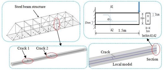
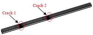
This paper firstly conducted finite element simulation on concrete steel bridge without cracks and with cracks. Fig. 1 showed the model of concrete steel bridges and beams. Model scale was 1:10. Model size of different kind of concrete steel bridges was as follows:
Model 1: Concrete steel bridges were 8 m long and 1.5 m wide. There were no cracks in the concrete steel beam in the concrete steel bridge. The length of the concrete steel beam was 1.5 m; width was 0.03; thickness was 0.015; the level of concrete in the bridge was C30; density was 2400 kg/m3; elasticity modulus was 104N/mm and Poisson’s ratio was 0.35. The concrete steel beam contained some steel bars. The elasticity modulus of the steel bar was 105N/mm.
Model 2: Concrete steel bridges were 8 m long and 1.5 m wide. There were two cracks in each concrete steel beam in the concrete steel bridge. The length of the concrete steel beam was 1.5 m; width was 0.03; thickness was 0.015; the level of concrete in the bridge was C30; density was 2400 kg/m3; elasticity modulus was 104N/mm and Poisson’s ratio was 0.35. The concrete steel beam contained some steel bars. The elasticity modulus of steel bar was 105N/mm. These positions which were 400 mm and 600 mm away from both sides were a crack with a depth of 2 mm in the direction of width respectively.
Model 3: Concrete steel bridges were 8 m long and 1.5 m wide. There were two cracks in each concrete steel beam in the concrete steel bridge. The length of the concrete steel beam was 1.5 m; width was 0.03; thickness was 0.015; the level of concrete in the bridge was C30; density was 2400 kg/m3; elasticity modulus was 104N/mm and Poisson’s ratio was 0.35. The concrete steel beam contained some steel bars. The elasticity modulus of steel bar was 105N/mm. These positions which were 200 mm and 800 mm away from both sides were a penetrating crack with a depth of 2 mm in the direction of width respectively.
Table 1Crack parameters of three kinds of models for concrete steel beams in bridges
Different models | Model 1 | Model 2 | Model 3 |
Crack condition | No crack | Two cracks which were 400 mm and 600 mm respectively away from both sides of beams | Two cracks which were 200 mm and 800 mm respectively away from the both sides of beams |
Fig. 1Models of concrete steel beams and bridges
2.2. Mesh division
This paper used the software COMSOL for dividing meshes. It could adaptively generate meshes, and elements with good shapes and characteristics could be obtained. Mesh density in the area demanding for high accuracy could be automatically adjusted to ensure a high quality of meshes. Hexahedral solid elements were used for three kinds of models to divide meshes. 6 points were arranged along the width of concrete steel beams; 1 point was arranged along the thickness of concrete steel beams; 50 points were arranged along the length of concrete steel beam.
Fig. 2Finite element model of three kinds of concrete steel bridges
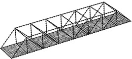
a) Concrete steel bridges
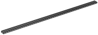
b) Beams in Model 1
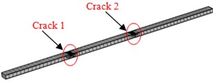
c) Beams in Model 2
d) Beams in Model 3
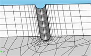
d) Crack
Model 1 had 51210 elements in total. Model 2 and Model 3 adopted tetrahedral meshes which were finely generated in the position of cracks. The minimum size of element was 0.02 mm; the maximum size of elements was 0.56; the growth rate of elements was 1.5; the average quality of meshes was 0.86, which was close to 1. Therefore, the requirements of computational accuracy and convergence were satisfied. Model 2 had 77574 elements in total; Model 3 had 79682 elements in total. The finite element model of three kinds of models was shown in Fig. 2.
2.3. Model computation and boundary conditions
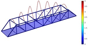
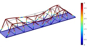
This paper used software COMSOL and adopted the three-dimensional concrete steel bridges with cracks to conduct modeling and establish high-precision finite element models. The concrete steel bridge was supported by bridge pier (Bridge pier was not shown in the figure). Bridge pier’s constraint of concrete steel bridges was assumed as simply support, and this boundary condition has been adopted in many reported papers. For example, Liang studied the influence of scour depth on modal parameters of simply supported bridge [16], and Wei studied continuous transformation and reinforcement for old simply supported hollow slab bridge [17]. This paper conducted modal analysis on the whole concrete steel bridge and computed the natural frequency and modal deformation of three kinds of models, as shown in Fig. 3-Fig. 5.
Fig. 3Three order modes of Model 1
a) First order
b) Second order
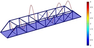
c) Third order
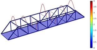
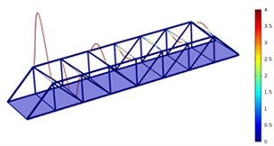
Fig. 4Three order modes of Model 2
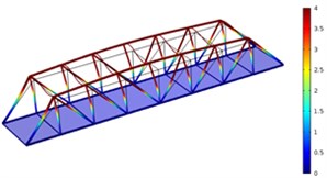
a) First order
b) Second order
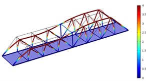
c) Third order
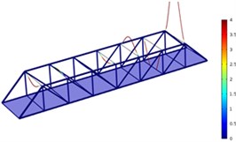
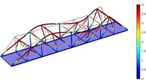
Fig. 5Three order modes of Model 3
a) First order
b) Second order
c) Third order
As shown in Fig. 3-Fig. 5, the vibration amplitude of nondestructive bridges was small and only focused on partial areas of concrete steel beams when the concrete steel beam in the concrete steel bridge had no cracks. When the concrete steel beam in the bridge had two cracks, the modal transformation of the whole bridge was large. Apart from the obvious vibration of the concrete steel beam, the whole bridge deck also deformed obviously. It could be seen that cracks in the concrete steel beam not only had an impact on the dynamic characteristic of the concrete steel beam, but also affected the dynamic characteristics of the whole bridge. In addition, the higher the order was for three kinds of models, the greater the deformation of the concrete steel bridge would be. Cracks had some impacts on the vibration frequency of the concrete steel bridge. In addition, different orders of modes showed different impacts. Compared with nondestructive bridges, the vibration frequency of bridges with cracks would be reduced. Higher order would have a greater impact on frequencies. Additionally, the amplitude of modes would be reduced. Higher order would have a smaller impact on the amplitude of modes.
3. Experimental verification
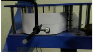
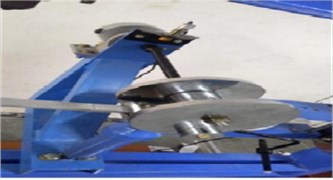
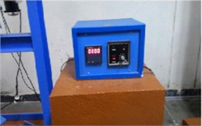
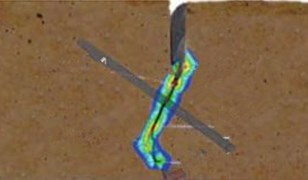
The change of dynamics was analyzed above when the whole concrete steel bridge and local beam had cracks. To verify the correctness of the finite element method in this paper, experimental analysis was conducted on three kinds of concrete steel beams with cracks. We cannot directly test the natural modal of the concrete steel bridge to verify the correctness of the finite element model because its size was very large and structure was relative complex. The concrete steel bridge was composed of some concrete steel beams, so the correctness of the computational model can be verified indirectly. Test pieces of concrete steel beams were made. Parameters of test models were the same with those of the finite element simulation. The experimental equipment of modal analysis was shown in Fig. 6. In the figure, 1 stood for the test piece of concrete steel beams which were 1.5 m long, 0.03 m wide and 0.015 m thick. 2 represented excitation equipment which excited the beam whose end was set as fixed through external power control box 6 and vibration excitation motor 5. In the meanwhile, data acquisition equipment of frequency analysis was used to keep record of natural vibration frequency. Fig. 7 presented the partial views of experimental equipment and cracks in concrete steel beams. The size of test pieces in this paper was the same with the actual size of structural beam in concrete steel bridges. Meanwhile, they had the same material properties.
Experimental result was obtained to compare with finite element result, as shown in Table 2. It could be seen from Table 2 that the finite element result of frequencies for three kinds of models was very close to the experimental result in the first, second and third orders. The maximum error was about 3 %, which was less than 5 %. As a result, the finite element model of concrete steel beams in this paper was right. Therefore, the computational model of concrete steel bridges which were composed of this concrete steel beam was also feasible. Based on the numerical simulation method, an analysis would be conducted then on the impact of different crack positions and depths on vibration frequencies.
Fig. 6Experimental equipment of modal analysis
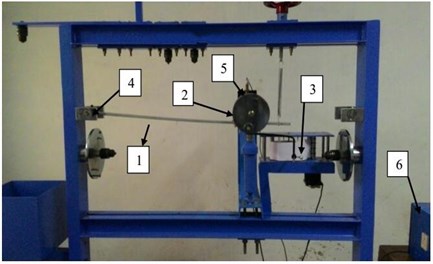
Fig. 7Experimental equipment and local cracks in concrete steel beams
a) Recording equipment of frequency analysis
b) Vibration excitation equipment
c) Power control box
d) Local cracks of testing pieces
Table 2Comparison between computational and experimental result of concrete steel beams
No. | Situations of beams | Experimental result / Hz | Computational result / Hz | ||||
First order | Second order | Third order | First order | Second order | Third order | ||
1 | No cracks | 12.576 | 78.687 | 220.27 | 12.584 | 78.789 | 220.3 |
2 | Cracks with a depth of 2 mm were 400 nm and 600 mm away from both ends, respectively | 12.498 | 78.498 | 219.30 | 12.549 | 78.513 | 219.36 |
3 | Cracks with a depth of 2 mm were 200 nm and 800 mm away from both ends, respectively | 12.525 | 78.499 | 221.96 | 12.527 | 78.535 | 220.07 |
4. Discussion and analysis
Numerical simulation and experiment were respectively conducted on three kinds of models. The comparison showed the correctness of the finite element method in this paper. Crack position and depth had serious impacts on the modal frequency of concrete steel bridges. Then, the numerical simulation method would be adopted to compute 50 groups of models to find out impact of related parameters of cracks on the dynamic response of concrete steel bridges. Model data was computed through the following two groups of analysis:
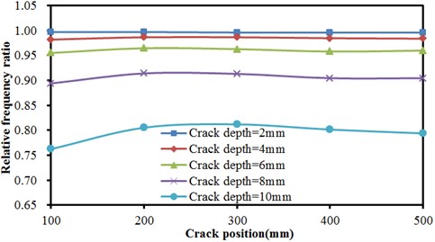
1) Crack position kept unchanged to respectively compute the impact of crack depths on the vibration frequency of concrete steel bridges. This paper selected concrete steel beams with two cracks and supposed the distance between two cracks was 500 mm. The distance between cracks and both ends was 100 mm, 200 mm, 300 mm, 400 mm and 500 mm. Dynamic responses were computed when crack depth was 2 mm, 4 mm, 6 mm, 8 mm and 10 mm respectively at the fixed position.
2) Crack depth kept unchanged to respectively compute the impact of crack positions on the vibration frequency of concrete steel bridges. In this paper, crack depth was 2 mm, 4 mm, 6 mm, 8 mm and 10 mm respectively. Dynamic responses were computed when cracks were 100 mm, 200 mm, 300 mm, 400 mm and 500 mm away from both ends under the fixed depth.
Fig. 8Frequencies of concrete steel bridges with crack depths
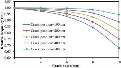
a) The first order vibration frequency
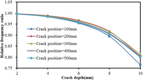
b) The second order vibration frequency
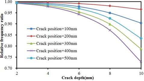
c) The third order vibration frequency
Fig. 9Frequencies of concrete steel bridges with crack positions
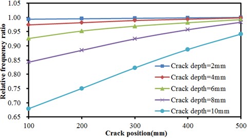
a) The first order vibration frequency
b) The second order vibration frequency
c) The third order vibration frequency
Many groups of models were computed to obtain the result, as shown in Fig. 8 and Fig. 9, Fig. 8 described the relationship of frequencies of concrete steel bridges with crack depth under three order modals when crack positions were unchanged. In the figure, three order frequencies were used for analysis. The horizontal ordinate in the figure was crack depth while the vertical ordinate represented relative frequency ratio. Frequency ratio was defined as the ratio of frequencies of defective bridges to the result of nondestructive bridges.
As shown in Fig. 8, the frequency of concrete steel bridges decreased non-linearly with the increased crack depth in the first order. Thus, it was clear that the impact of crack depths on the vibration frequency of concrete steel bridges was greater when cracks were closer to end of beams and the vibration frequency of concrete steel bridges would quickly decrease with the increased crack depth. In the second order, the frequency of concrete steel bridges also decreased non-linearly with the increased crack depth. However, crack depths had no obvious impact on frequencies. For the same crack depth which was 10 mm, frequencies decreased most seriously when crack was 100 mm away from the end of beams. Compared with frequencies under other situations, frequency ratio in this order will reduce by about 0.05 at most. In the third order, the frequency of concrete steel bridges also decreased non-linearly with the increased crack depth. When crack positions were different, result curves presented a more obvious difference when crack depths were larger. Different from the top two orders, the frequency of concrete steel bridges decreased most seriously when cracks were 400 mm away from the end of beams, followed by 300 mm, 500 mm, 100 mm and 200 mm.
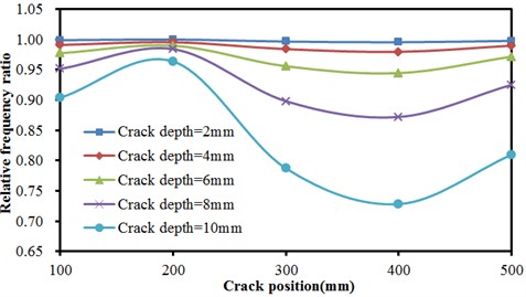
Fig. 9 described the relationship of relative frequency ratio of concrete steel bridges with crack positions under different crack depths in the first, second and third orders. As shown from Fig. 9, the frequency ratio of concrete steel bridge increased approximately linearly with the increased distance of crack from the end of beams in the first order. In the second order, frequency ratio was not obviously related to crack positions when crack depths were small (less than 6 mm). At different crack positions, frequency ratios were basically the same. With the increased crack depth, frequency ratios at different crack positions started to show obvious differences. In the third order, crack positions still had no impact frequency ratio when crack depths were less than 4 mm. In addition, frequency ratio obviously decreased with the increased crack depth. When crack positions were less than 200 mm, frequency ratio slightly increased with the increased crack positions. Then, frequency ratio presented a trend of decreasing quickly with the increased crack positions. When crack positions were 400 mm, frequency ratio stopped decreasing. Frequency ratio slightly increased with the increased crack positions.
Fig. 10The crack position was 300 mm and crack depth was 2 mm
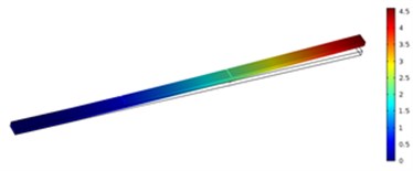
a) First order
b) Second order
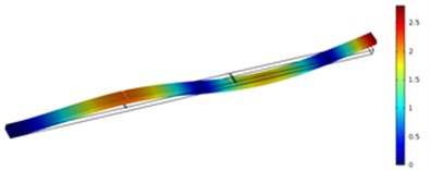
c) Third order
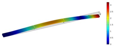
Fig. 11The crack position was 500 mm and crack depth was 10 mm
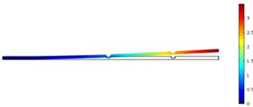
a) First order
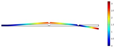
b) Second order
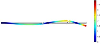
c) Third order
In order to carefully observe the vibration characteristics of concrete steel beams in bridges with different crack depths and positions, Fig. 10 and Fig. 11 displayed vibration contours of different orders of concrete steel beams. Due to the limitation of paper length, only a part of contours of computational results were listed. According to the above results, different modal orders and crack depths had a great impact on frequency ratio with the increased crack depth. Due to the expansion of cracks, stiffness of concrete steel beams was weakened, whose dynamic characteristics would be also reduced obviously. Compared with the situation of three orders, crack depths had the greatest impact on the first order, followed by the third order and the second order. In addition, crack positions also had some impacts on frequency ratio and had a greater impact on the first and third orders because the crack position was closely related to the modes of concrete steel beams. Additionally, crack positions obviously had different impacts on the third order compared with the top two orders. When crack positions were 400 mm, frequency ratio had the greatest impact because the crack position was close to the maximum deformation of the third mode. Therefore, it had the greatest impact on the frequency.
The most obvious impact was on the vibration of the first order when the crack was the closest to the end in the case of the same crack depth, followed by the second order and then the third order. Through comparing three orders, the weakening effect on the structure reduced resistance moment most obviously when the crack was the closest to the end of beams as the first order had the maximum bending moment at the fixed end. In addition, the impact of crack positions on the frequency of bridges could be neglected when crack depths were small. Moreover, the impact of crack positions on the third order was obviously different from that on the top two orders. When the crack was away from the end of beams, frequency ratio decreased to some extent. It was because the crack was at the position where the vibration deformation of the third order was relatively large.
In conclusion, crack positions and depths had some impacts on the dynamic characteristics of concrete steel bridges. With the increased crack depth, the weakening effect on concrete steel bridges led to the decrease of vibration frequencies. The closer the crack was to the end of beams, the more obvious the weakening effect of dynamic characteristics of concrete steel bridges under the first order and the second order would be. Different orders of modes needed to be considered in the case of analyzing the impact of crack positions. When the crack was at the position where the deformation of beams was relatively large, crack positions had a greater impact on the dynamic characteristics of concrete steel bridges compared with the crack close to the end of beams.
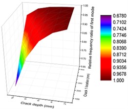
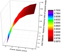
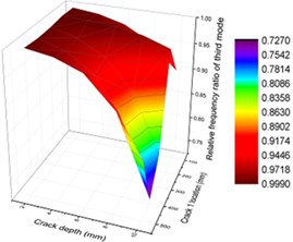
Fig. 12Contours of frequency ratio of concrete steel bridges with crack positions and depths
a) First order
b) Second order
c) Third order
To display the impact of crack depths and positions on vibration characteristics of concrete steel bridges more intuitively, three-dimensional surface diagram was drawn, as shown in Fig. 12. From the figure, it could be seen that vibration frequencies had similar change in the first and second orders when the combined impact of crack depths and positions was considered. With the increased crack depth, crack positions were closer to the end of beams and vibration frequencies were smaller. From specific values, it could be seen that the first-order frequency had a greater impact on the second-order frequency. In addition, vibration frequencies were smaller in the third-order vibration with the increased crack depth. When crack depth was relatively small, changes of vibration frequencies with crack positions were not obvious for the whole orders.
5. Conclusions
This paper studied the dynamic characteristics of concrete steel bridges composed of concrete steel beams with two cracks. Firstly, this paper adopted the finite element method to build a finite element model for the concrete steel bridge under three different conditions, and obtained vibration frequencies and modes. Then, this paper made test pieces for three kinds of concrete steel beams, conducted modal analysis and test, compared computational results with experimental results and verified the correctness of the simulation model. In addition, this paper analyzed the impact of different crack depths and positions on the dynamic characteristics of concrete steel bridges with cracks based on numerical simulation method and obtained the following conclusions:
1) The vibration frequency of concrete steel bridges with cracks was greatly affected by cracks. The higher the order was, the greater the impact of cracks on frequencies would be and the smaller the impact of cracks on the mode amplitude would be.
2) Crack depths had a great impact on the vibration frequency of concrete steel bridges. In addition, the impact became increasingly obvious with the increased crack depth. Due to the expansion of cracks, the structural performance of beams will be weakened, which thus caused changes in the dynamic characteristics and reduced vibration frequencies.
3) When cracks were closer to the end of beams, the first and second orders of vibration frequencies of concrete steel bridges would be greatly affected. When cracks were far away from the end of beams, the vibration frequency of the third order would be greatly affected because the crack position was closely related to the modal of beams.
4) Through comparing three order vibrations, cracks had the most obvious impact on the first order vibration of concrete steel bridges. In addition, the vibration frequency of three orders did not obviously change with crack positions when crack depths were very small.
5) Numerical simulation model and method in this paper provided foundation and reference for continuing to analyze concrete steel beams with other crack forms or other structural forms. In the meanwhile, the three-dimensional analytical contour in this paper could help engineers to more intuitively understand and valuably apply the change rule of impact of crack depth and position on concrete steel beams.
References
-
Shen W. H. Structural Damage Detection Based on Experimental Modal Analysis. Jinan University, Guangdong, 2006.
-
Huang X. Numerical Simulation Research on the Structural Damage. Tongji University, Shanghai, 2008.
-
Ren W. X., De Roeck G. Structural damage identification using modal data. I: Simulation verification. Journal of Structural Engineering, Vol. 128, Issue 1, 2002, p. 87-95.
-
Ravanfar S. A., Razak H. A., Ismail Z., Hakim S. J. A two-step damage identification approach for beam structures based on wavelet transform and genetic algorithm. Meccanica, Vol. 51, Issue 3, 2016, p. 635-653.
-
Wang D., Chen Z., Xiang W., Zhu H. Experimental investigation of damage identification in beam structures based on the strain statistical moment. Advances in Structural Engineering, 2016, p. 1-12.
-
Dawari V. B., Vesmawala G. R. Structural damage identification of beam structures using two stage method based on modal strain energy indicators and artificial neural networks. Journal of Vibroengineering, Vol. 18, Issue 1, 2016, p. 1-10.
-
Mininni M., Gabriele S., Lopes H., Santos J. Damage identification in beams using speckle shearography and an optimal spatial sampling. Mechanical System and Signal Processing, Vol. 79, 2016, p. 47-64.
-
Nandakumar P., Shankar K. Structural damage identification using transfer matrix with lumped crack properties. Inverse Problems in Science and Engineering, Vol. 24, Issue 3, 2016, p. 1-26.
-
Baghani M., Mazaheri H., Salarich H. Analysis of large amplitude free vibrations of clamped tapered beams on a nonlinear elastic foundation. Applied Mathematical Modelling, Vol. 38, Issue 1, 2014, p. 1176-1186.
-
Allahverdizadeh, et al. Nonlinear vibration of FGER sandwich beams. International Journal of Mechanical Sciences, Vol. 78, 2014, p. 167-176.
-
Wang L., et al. Large amplitude vibration and parametric instability of inextensional beams on the elastic foundation. International Journal of Mechanical Sciences, Vol. 67, 2013, p. 1-9.
-
Wang Z. H., Chen Z. B., Zhang W. W. Studies on crack parameter identification in a cantilever beam using natural frequencies. Journal of Vibration Engineering, Vol. 17, 2004, p. 906-909.
-
Salawu O. S., Williams C. Structural damage detection using experimental modal analysis-a comparison of some methods. Proceedings of 11th International Modal Analysis Conference, 1993, p. 254-260.
-
Sadettin O. Analysis of free and forced vibration of a cracked cantilever beam. NDT & International, Vol. 40, 2007, p. 443-450.
-
Peng Z. K., Lang Z. Q., Billings S. A. Crack detection using nonlinear output frequency response functions. Journal of Sound and Vibration, Vol. 301, 2007, p. 777-778.
-
Liang F. Y., Wang C., Jia C. Y., Wang Y. Model test on the influence of scour depth on modal parameters of simply supported bridge. Journal of Vibration and Shock, Vol. 35, Issue 14, 2016, p. 145-150.
-
Wei J. G., Huang L., Li P. Y., Wu Q. X. Research on continuous transformation and reinforcement for old simply supported hollow slab bridge. Journal of Architecture and Civil Engineering, Vol. 31, Issue 4, 2014, p. 103-109.
Cited by
About this article

