Abstract
In this paper, a finite element mathematical model to evaluate natural frequencies and Frequency Response Functions (FRFs) of an L-shaped cracked beam structure is established. Dynamics of L-shaped beam structure is a very challenging subject and very little information is reported in literature. L-shaped beam structure is assumed to be fixed at end of the vertical column and free at the other end of the horizontal column. Natural frequencies are evaluated using finite element method in MatLab and simulations using Ansys (Version 18.2) is carried out to validate the mathematical model. Totally 18 cases with different crack positions and three different crack depths are considered for the analysis. Results obtained by both methods are tabulated and find a very good agreement in the results. Reported results can be used as a benchmark for further study of crack propagation and fatigue failure analysis in built-up structures.
1. Introduction
Dynamic analysis of structures is one of the very fascinating subjects for many researchers for over many decades. Simple beams such as cantilever and fixed-fixed beams form basic beam structures. Similarly, in the case of built-up structures, L-shaped beam forms a basic structure. L-shaped beams find its applications in various engineering fields, varying from electronic instruments, marine (hull) and railway structures, solar panel mounts, fencing profiles, Pagoda tents, Aluminium heat sinks and several modular workstations.
In the past decades, many researchers have extensively worked on the structural dynamics in finding natural frequencies and mode shapes for various beams with varying boundary conditions. In the field of engineering, even though one has many applications of built-up structures, seldom reports have been made on the dynamic analysis of these structures.
To study the beam characteristics, research has shown further interest in dynamic analysis of cracked beams. Khnaijar and Benamar [1] presented a new discrete physical model to approach the problem of cracked beam vibrations. Parametric studies facilitating the diagnostics process involving both crack localization and depth estimation are made. Agarwalla [2] studied the effect of an open crack on the vibrational parameters of the cantilever beam subjected to free vibration. The results obtained from the finite element method are compared with the experimental results. Khaji et al. [3] presented an analytical approach for crack identification procedure in uniform cracked beams based on bending vibration measurements. Analytical method considering Timoshenko beam theory is validated with the numerically obtained results by finite element method. Khiem and Toan [4] proposed a novel approach for calculating the natural frequencies of a multiple cracked beam and detecting unknown number of multiple cracks from the measured natural frequencies. The obtained results are validated with both numerical and experimental results.
As per the knowledge of the authors, a mathematical model to evaluate the dynamic characteristics of cracked L-shaped beam structures has not been reported. The present work reports the dynamic characteristics of L-shaped beams with and without crack, using both analytical and simulation approaches. Various depths of crack are taken into consideration and observed trends are elaborated. The natural frequencies and their percentage of error between Analytical and Simulation approaches are reported. In the simulation approach, type of meshing used to minimize computing time is mentioned. The mode shape behaviour and FRF characteristics, both point and transfer are reported.
2. Mathematical model
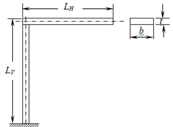
An L-shaped built-up beam structure as shown in Fig. 1 is considered.
Fig. 1L-shaped structure
L-shaped beam is assumed to be vibrating in a single plane and assumed to be made of 2D beam elements. Each node of an element is consisting of three degrees of freedom, viz., axial, transverse and rotational. The equation of motion for an element under free-vibration can be written as:
The structure considered requires only vertical and horizontal elements. The element stiffness and mass matrices for both vertical and horizontal elements are given (Kwon and Bang [5]) as follows.
Element stiffness matrix for vertical column is given by:
Element mass matrix for vertical column is given by:
Element stiffness matrix for horizontal member is given by:
Element mass matrix for horizontal member is given by:
Relations for , , and are given as follows:
where:
and is the length of each element in meters.
For the cracked beam-element, it is assumed that the elemental stiffness () is modified with no mass-loss due to crack, as it is very small when compared to the whole mass of the beam. Stiffness matrix for the cracked beam-element is evaluated considering the change in second moment of area. Global matrix for both stiffness and mass matrices are obtained by appropriately placing the stiffness matrix of cracked beam-element as per conventional matrix assembly.
3. Numerical case studies
There are two cases, viz., predicting natural frequencies and generating FRFs of L-shaped beam structure considered for analysis. The material properties and dimensions of the structure are listed in Table 1. The vertical arm of the structure is assumed to be fixed at one end and the horizontal arm is perpendicular to vertical arm and is free at the other end. and stands for length of vertical and horizontal arms respectively.
Table 1L-shaped beam structure material property and geometry
Parameters | Notation | Value |
Width | 0.03m | |
Thickness | 0.006 m | |
Young’s modulus | 71 GPa | |
Density | 2,710 kg/m3 | |
Poisson’s ratio | 0.3 |
MatLab coding is generated to estimate the analytical natural frequencies of the structure using Eqs. (2)-(5)). In the case of simulation, four different mesh types are initially used, viz., Multi-zone, Sweep mesh, Tetrahedron mesh and Hex-dominant mesh. It is noticed that Tetrahedron mesh gives the most accurate solutions when compared to analytical solutions, but the computation time is very large. Whereas, Hex-Dominant mesh takes the least computational time, without compromising on the non-decimal accuracy in predicting the natural frequencies. For all simulations model only Hex-Dominant mesh is used.
3.1. Uncracked L-shaped beam structure
Under this section, seven examples with different lengths for both vertical and horizontal arms are considered without crack on the structure. First three natural frequencies, both analytical and simulation are evaluated. The dimensions and the evaluated natural frequencies for both the approaches are tabulated in Table 2.
Table 2Natural frequencies of the L-shaped beam structure of cross section 30×6 mm without crack
Arm length | 1st mode | 2nd mode | 3rd mode | |||||||
(m) | (m) | (Hz) | (Hz) | Error (%) | (Hz) | (Hz) | Error (%) | (Hz) | (Hz) | Error (%) |
0.40 | 0.40 | 10.49 | 10.52 | 0.29 | 28.57 | 28.80 | 0.80 | 141.01 | 141.16 | 0.11 |
0.40 | 0.30 | 13.41 | 13.45 | 0.30 | 40.59 | 41.00 | 1.00 | 175.77 | 176.45 | 0.39 |
0.40 | 0.20 | 17.08 | 17.12 | 0.23 | 69.47 | 70.45 | 1.39 | 202.25 | 203.81 | 0.77 |
0.40 | 0.10 | 22.13 | 22.15 | 0.09 | 137.49 | 138.39 | 0.65 | 307.07 | 314.33 | 2.31 |
0.30 | 0.40 | 13.53 | 13.58 | 0.37 | 37.85 | 38.22 | 0.97 | 159.38 | 159.52 | 0.09 |
0.20 | 0.40 | 17.27 | 17.36 | 0.52 | 60.56 | 61.40 | 1.37 | 171.92 | 172.24 | 0.19 |
0.10 | 0.40 | 22.23 | 22.39 | 0.71 | 130.69 | 132.48 | 1.35 | 211.70 | 215.00 | 1.53 |
It is observed that a maximum percentage of error is 2.31 % at 3rd mode for the case 0.4 m and 0.1 m, and a minimum error of 0.09 % at 1st mode for the case 0.4 m and 0.1 m and as well as at 3rd mode for the case 0.3 m and 0.4 m. It indicates a good agreement between analytical and the simulation approaches in predicting the natural frequencies. Further, it can be noticed the percentage error is having an increasing tendency as the length of the arms decreases individually, keeping the length of the other arm unchanged in both the cases.
3.2. Cracked L-shaped beam structure (crack at mid-position)
In this case, L-shaped beam structure with crack at mid-position with three various depths on both vertical and horizontal arms is considered. Equal length of both the arms is considered and is equal to 400 mm. Structure is modelled as shown in Fig. 2. Point indicates the point of inter-section of both the arms. The position of the crack on vertical arm is indicated by with reference to point and similarly indicates the position of the crack on horizontal arm with respect to the same point . Presence of crack is complex in nature. For analytical approach using MatLab, the element containing the crack is modelled as reduction in the stiffness corresponding to the depth of crack.
Fig. 2Structure with crack at mid-position
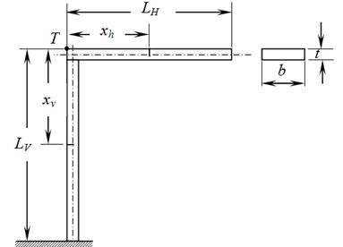
A total of 201 elements on both the arms are considered. Simulation analysis is carried out using Ansys (18.2). There are nine examples with different crack depths on both vertical and horizontal arms that are considered. It is noticed that presence of crack with different depth only on the horizontal arm makes no significant change in the first natural frequency. In the second and third natural frequencies, a reduction trend is noticed. Whereas, in presence of crack with a different depth only on the vertical arm makes no significant change to the second natural frequency. But, a significant reduction in value of 1st and 3rdnatural frequencies can be noticed. When the crack is present on both the arms, reduction in the value of natural frequency is observed in all the three modes as the depth of crack increases.
Table 3Natural frequencies of L-shaped cracked beam (LV= 400 mm and LH= 400 mm)
Crack depth (mm) | Crack position | 1st mode | 2nd mode | 3rd mode | |||||||
() | () | (Hz) | (Hz) | Error (%) | (Hz) | (Hz) | Error (%) | (Hz) | (Hz) | Error (%) | |
1 | 0.00 | 0.50 | 10.49 | 10.53 | 0.38 | 28.56 | 28.8 | 0.83 | 140.68 | 140.69 | 0.01 |
0.50 | 0.00 | 10.47 | 10.50 | 0.29 | 28.56 | 28.8 | 0.83 | 140.87 | 141.01 | 0.10 | |
0.50 | 0.50 | 10.47 | 10.50 | 0.29 | 28.56 | 28.79 | 0.80 | 140.54 | 140.61 | 0.05 | |
2 | 0.00 | 0.50 | 10.49 | 10.53 | 0.38 | 28.53 | 28.76 | 0.80 | 139.94 | 139.54 | 0.29 |
0.50 | 0.00 | 10.44 | 10.45 | 0.10 | 28.56 | 28.79 | 0.80 | 140.54 | 140.52 | 0.01 | |
0.50 | 0.50 | 10.44 | 10.45 | 0.10 | 28.53 | 28.75 | 0.77 | 139.50 | 139.01 | 0.35 | |
3 | 0.00 | 0.50 | 10.49 | 10.52 | 0.29 | 28.47 | 28.70 | 0.80 | 137.90 | 136.90 | 0.73 |
0.50 | 0.00 | 10.34 | 10.31 | 0.29 | 28.56 | 28.80 | 0.83 | 139.65 | 139.32 | 0.24 | |
0.50 | 0.50 | 10.33 | 10.30 | 0.29 | 28.47 | 28.66 | 0.66 | 136.69 | 135.23 | 1.08 | |
However, this reduction trend is more significant when the crack is present on the vertical arm. Further, the percentage of errors in predicting the natural frequencies between analytical approach and simulations are less than 0.38 %, 0.83 % and 1.08 % for first three natural frequencies respectively.
3.3. Frequency response functions (FRFs) of uncracked and cracked L-shaped beam structures
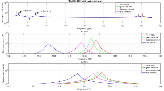
Frequency Response Functions (FRFs) of structures plays an important role in understanding the response of the structures for various points of excitation. In this section, there are two cases: transverse point FRFs and transverse transfer FRFs are generated. For both the cases, mid-position crack with various crack depths on equal length of 400 mm on vertical and horizontal arms is considered. Fig. 3 shows four overlapped transverse point FRFs (1205x, 1205y) for no crack and crack of three depths. Sub-plot of Fig. 3 shows a blow-up view of 1st and 2nd mode of peak response. In the same way, a set of transverse transfer FRFs (905x, 1205y) for no crack and three crack depths are generated and shown in Fig. 4. In both the cases, it is clearly visible that the natural frequency decreases as crack depth increases. The response level is not discussed as the study is on undamped structures.
Fig. 3Transverse point FRFs (1205x, 1205y) of uncracked and cracked L-shaped structure
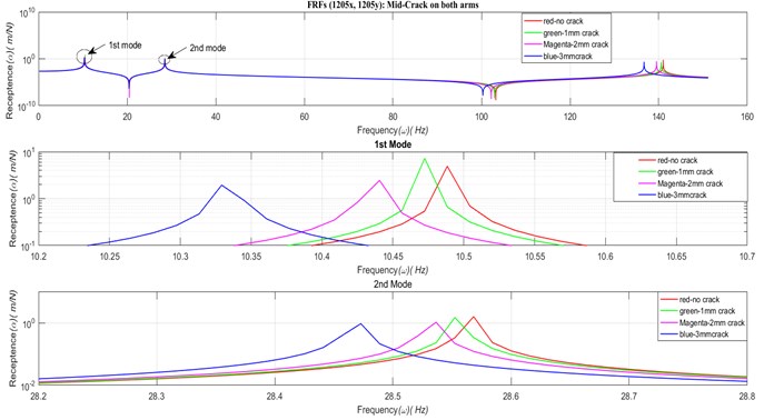
Fig. 4Transverse transfer FRFs (905x, 1205y) of uncracked and cracked L-shaped structure
4. Conclusions
Mathematical model to predict natural frequencies and Frequency Response Functions (FRFs) of an L-shaped cracked beam structure is established. Natural frequencies are evaluated using finite element method using MatLab and results are validated by carrying simulations using Ansys (Version 18.2). Results obtained using MatLab is having a very good agreement with the simulation results. Reported results can be used as a benchmark for further study of crack propagation and fatigue failure analysis in built-up structures.
References
-
Khnaijar Ahmed, Benamar Rhali A new model for beam crack detection and localization using a discrete model. Engineering Structures, Vol. 150, 2017, p. 221-230.
-
Agarwalla D. K., Parhi D. R. Effect of crack on modal parameters of a cantilever beam subjected to vibration. Procedia Engineering, Vol. 51, 2013, p. 665-669.
-
Khaji N., Shafiei M., Jalalpour M. Closed-form solutions for crack detection problem of Timoshenko beams with various boundary conditions. International Journal of Mechanical Sciences, Vol. 51, 2009, p. 667-681.
-
Khiem N. T., Toan L. K. A novel method for crack detection in beam-like structures by measurements of natural frequencies. Journal of Sound and Vibration, Vol. 333, 2014, p. 4084-4103.
-
Kwon Y. W., Bang H. The Finite Element Method using MatLab. CRC Press LLC, Boca Raton, London, 1997.
About this article

