Abstract
This work is focused on determining the response of a multi-cracked structure in the presence of different types of cracks vibrated due to a transit mass. The open transverse and inclined edge cracks of random crack depth are present at various locations of the cracked structure. The mass is moving on the beam at the different critical speeds of the structure. Runge-Kutta fourth order method is employed to evaluate the response of the structure numerically. The significance of different factors like the magnitude of the moving mass, moving speed, crack depth, crack inclination angle and their effects on the response of the deteriorated structure are investigated. Numerical analyses with numerous examples are carried out and validated the results with finite element analysis (FEA) and experimental investigations.
1. Introduction
The moving load dynamics problem is an important research topic both in the field of structural dynamics and transportation engineering. The stability and properties of the structure may change due to the presence of cracks. Numerous studies have been conducted on cracked structures with moving load to examine the stability and response of structures. Lee and Ng [1] have studied the dynamic behaviour of a cracked beam subjected to traversing mass using Euler-Bernoulli’s theory and assume mode technique. The transverse vibration of a slender beam with inclined edge cracks has been explained by Nandwana and Maiti [2] using the rotational spring method. Chaudhari and Maiti [3] proposed an analytical technique to study the transverse vibration of cracked cantilever beam with edge crack of linearly variable crack depth. Ichikawa et al. [4] investigated the response of a multi-span Euler-Bernoulli beam subjected to traversing load by employing both the modal analysis and the direct integration method. Wu et al. [5] have applied both the analytical and finite element methods to obtain the dynamic response of mobile gantry crane structures. An iterative modal analysis method has been developed to examine the consequence of transverse crack on the response of an undamped Bernoulli-Euler beam with traversing mass by Mahmoud and Abouzaid [6]. Karuppaiah et al. [7] studied the dynamic behaviour of a light passenger vehicle by experimentation and finite element analysis. Bilello and Bergman [8] have conducted an analytical and experimental study to determine the response of a damaged Euler-Bernoulli beam subjected to a traversing mass. Law and Zhu [9] have studied the dynamic response of damaged concrete bridge subjected to traversing vehicle. Employing the differential quadrature method (DQM), Hsu [10] studied the eigenvalues problems of cracked structure on the elastic foundation subjected to axial loading, excitation force and single edge crack. A finite element analysis of vehicle-bridge interaction using commercial programme LS-DYNA was carried out by Kwasniewski et al. [11]. Nikkhoo et al. [12] have investigated the dynamic behaviour and modal control of structures under the excitation of traversing mass. Aydin [13] has developed a theoretical method for the evaluation of vibrational frequencies and mode shape functions of axially loaded cracked structure in the presence of non-breathing cracks. Ariaei et al. [14] have employed the discrete element technique and the finite element method to evaluate the dynamic response of cracked beam with open and breathing cracks under the excitation of traversing mass. They have also discussed various parameters that affecting the response of the structure. Behzad et al. [15] have developed a continuous model to analyse flexural vibration of a beam with vertical edge crack.
Shafiei and Khaji [16] have developed an analytical solution method to examine the free and forced vibration of a cracked Timoshenko beam with multiple cracks under the excitation of an intense traversing load. Dyniewicz [17] has explained the response of structure subjected to a traversing inertial load using the space-time finite element method. Zarfam and Khaloo [18] have studied the vibration control of structures on the elastic foundation under traversing mass and random lateral excitations using modal analysis method. Behzada et al. [19] proposed a crack detection algorithm for a cantilever beam structure with two different types of cracks. Azam et al. [20] have studied the dynamic behaviour of Timoshenko beam under the action of both traversing mass and traversing sprung structures. Cicirello and Palmeri [21] have presented a method for the static analysis of an Euler-Bernoulli beam with random no of unilateral cracks under the action of both axial and transverse load. Nezad et al. [22] have determined the natural frequencies and mode shapes of a double cracked simply supported structure by extending the Rayleigh's method. Zhong et al. [23] have explored the vehicle- bridge interaction dynamics by considering the prestress effect of a bridge. Nguyen [24] discussed the importance of crack on the dynamic behaviour of bridge type structure excited due to moving vehicle and earthquake. He has modelled the bridge structure as a 3-D beam using FEM.
Numerous studies have been conducted for the investigation of stability and dynamic behaviour of damaged structures subjected to moving load using theoretical, computational, experimental and finite element methods. But little attention has been focused on the cracked structure with the presence of different types of crack in static analysis of structure. But, this work investigates the response of the cracked structure under the excitation of traversing mass with the presence of open transverse and inclined edge cracks. Numerical analyses followed by experimental and finite element analyses have been exemplified to validate the employed numerical method.
2. Problem formulation
The dynamic response of a damaged cantilever beam (multiple cracks) with different types of cracks of random crack depth, length , width , thickness , subjected to a transit mass is analysed. The cracked beam contains open transverse cracks and inclined edge crack.
Fig. 1Schematic view of cracked beam subjected to transit mass different types of cracks
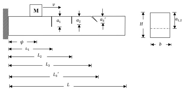
A mass of is traversing across the beam with speed from the fixed end to the tip end as in Fig. 1. An undamped uniform Euler-Bernoulli beam with no loading condition is considered in this study. Including inertial & shearing effects, ignoring the longitudinal vibration and damping effects of the beam, the equation of motion of the beam subjected to transit mass is given as:
where – transit mass-beam contact force .
– position of the transit mass at time :
where, – beam transverse deflection, is Dirac delta function, is beam mass per unit length, – total beam mass, is acceleration due to gravity, is Flexural rigidity (undamaged beam), is mass density (constant) of the beam.
The solution of Eq. (2) can be written in series form i.e.:
where is function of position or eigenfunctions of the beam without considering the transit mass, is time function to be calculated.
To determine , the Eq. (3) may be written as:
where , 5 is no of modes of vibration, is natural frequency of the beam
The magnified view of the inclined crack segment of the beam is explained in Fig. 2. The modelling of cracks is done in FEA using ANSYS WORKBENCH 2015. Due to the existence of inclined edge crack, the crack depth is changing throughout the crack segment. The dimensions of the inclined crack segment are as follows:
is maximum crack length, is maximum crack length at the crack opening, is maximum depth at the crack intact position.
Fig. 2Inclined cracked zone in magnified view
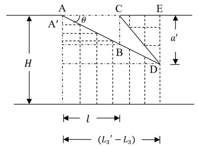
is relative depth at the intact positions , is relative crack depth, is crack inclination angle, , , are position of the 1st, 2nd and 3rd cracks from the fixed end. Now the entire crack length () may be subdivided into no of equal parts i.e. 1, 2, 3,…, . From the geometry of Fig. 2, the dimensions for the inclined crack section are as follows , length of each part in the crack segment , length of th part of the segment .
The thickness of the first section below the inclined crack zone .
The th part of the thickness below the inclined zone .
Similarly, the thicknesses above the inclined zone are calculated. From the geometry of the inclined crack zone, the crack depth and relative crack depth for the inclined crack segments are calculated. Due to the existence of different types of cracks, the entire beam can be simulated into different beam segments. From the assumptions of Euler-Bernoulli’s beam theory, the solution of Eq. (4) for the transverse deflection of each segment of the beam can be stated as:
where , , and are different integrating constants, evaluated from various end conditions [25].
Using Eq. (3) on the right part of the Eq. (2) and arranging it, we get:
Multiplying in Eq. (5) and integrating it over , the Eq. (6) thus developed can be expressed as:
The expression on the right of Eq. (6) can be expressed as: .
From orthogonality principle and Dirac delta function properties, the Eq. (6) can be written as:
From the orthogonality principle as:
Combination of Eqs. (2) and (5) can be expressed as:
With no of steps, combination of Eqs. (8) and (9) can be expressed as:
Employing the values of Eqs. (3) in Eq. (10), the equation now:
Obtaining values from Eq. (4) and applying in Eq. (11), and rearranging it:
Now, the Eq. (12) must satisfy each value of i.e.:
For the solution of Eq. (13), a computational method of Runge-Kutta fourth order rule is adopted.
3. Numerical formulation
A structural steel beam specimen of size 1.5 m×0.05 m×0.0045 m with appropriate assumptions is made for the analysis. The cracks are located (0.4, 0.75, 1.1 m) from the fixed end of the beam. The critical speed () of the cantilever beam is calculated considering the first mode of the structure. The flexural rigidity () of the undamaged beam is also calculated. The transit mass has been considered at the different beam to mass ratio (0.4 m, 0.6 mkg) and the transit speed regarding different critical speed (, km/h) of this structural systems. The response of the multi-cracked structure with different types of cracks has been calculated at different crack depth ratio (), speeds, moving mass, crack inclination angles and crack locations. For the solution of the computational method, a MATLAB code has been developed. Parametric analyses have been conducted with different factors affecting the response of the structure.
4. Finite element analysis
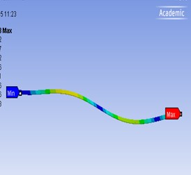
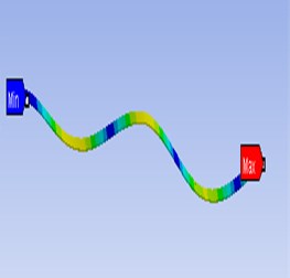
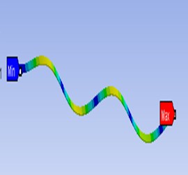
The finite element analysis has been carried out using the standard commercial ANSYS WORKBENCH 2015 package for the damaged structure. Primarily modal analysis is conducted to determine the natural frequencies and mode response of the structure (damaged and undamaged) considering the first five modes of vibration. The modelling of cracks is done in FEA. Transient dynamic analysis of mode superposition method is employed to determine the response of the structure with the transit mass and speed. The inertial effect is considered and the damping effect is ignored. The beam displacements at the tip end and the transit mass point (position of the mass on the beam during motion) are calculated. The transit mass in finite element model (Fig. 3) and modal behaviours of the cracked structural system at different modes are described in Fig. 4(a)-4(c). The modelling of cracks is done in FEA. The crack modelling for inclined edge crack (30°, 0.45) and transverse open crack (0.45) are shown in Fig. 5(a) and (b) respectively. The frequency analyses in the presence of different types of cracks on the structure are explained in Table 5.
Fig. 3Transit mass in finite element model
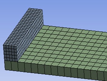
Fig. 4Modal behaviour of the structure at different modes for θ1,2= 30°, α1,2'= 0.45, 0.6, α= 0.45
a)
b)
c)
Fig. 5Enhanced view of crack zone
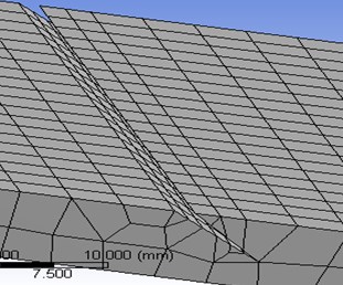
a) Inclined edge crack at 30°, 0.45
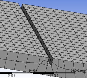
b) Transverse open crack at 0.45
5. Experimental analysis
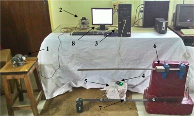
For the experimental arrangements, the types of equipment are incorporated as in Fig. 6. The different types of equipment used in the experiment are explained in Table 1. A structural steel beam specimen of size 1.5 m×0.05 m×0.0045 m, linear mass density 7850 kg/m3, flexural rigidity (undamaged) 75.938 Nm2 are considered for the experimental investigation. The cracks are made using the wire EDM machine at the appropriate position of the beam. Several precautions are taken during the experiments. The position of the variac is regulated precisely to attain the required constant speed of the transit mass and the best possible accuracy in measurements.
The transit mass is sliding (no slipping) across the beam by a rope attached to the motor. During the movement of the transit mass across the cracked beam, the beam deflections at different locations of the mass are recorded through the sensors and displayed on the monitor through the data acquisition unit. The average readings of the deflections at the different location of the mass determined through the sensors are considered the beam deflection at that location. Several tests are carried out at different speeds and weight of the transit mass to calculate the beam deflections.
Table 1Equipments used in the experiments
Serial No. | Equipment | Serial No. | Equipment |
1 | Motor (AC) | 5 | Breadboard |
2 | Variac | 6 | Transit mass |
3 | Data acquisition unit | 7 | Sensors(ultrasonic) |
4 | Microcontroller | 8 | Monitor |
Fig. 6Experimental setup
6. Results and discussion
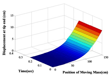
The response of a damaged cantilever beam with multiple different types of cracks subjected to transit mass is explained at different moving speed and mass. Numerical analysis along with finite element analysis and experimental verification are carried out to validate the applied computational method. The analysis has been carried out at constant crack locations ( 0.4, 0.75, 1.1 m). The dynamic deflection (Numerical and FEA) of the cracked beam with the existence of inclined edge crack and transverse open cracks at different locations of the transit mass at different speeds are determined and explained from Figs. 7-10 and that of transverse open cracks and inclined edge crack in Table 2. From the computational analysis, the dynamic behaviour of the cracked beam at various positions of the transit mass with transit time is explained in 3-D graph in Fig. 11 (inclined edge cracks and transverse open crack) and from Figs. 12-13 (transverse open cracks and inclined edge crack) at constant crack locations (0.4, 0.75, 1.1 m). It has been observed that at the lower speed of the transit mass, the deflection produced is more than that of higher speed. It’s because, at the lower speed, the lower modes of the structure are greatly excited than that of higher speed. With the increase of the magnitude of the transit mass and crack depth, the beam deflection also increases. If the angle of crack inclination increases, then the length of crack decreases, which leads to the reduction in dynamic beam deflection.
Fig. 7For v= 0.6vc km/h, L1,2,3= 0.4, 0.75, 1.1 m, α1,2= 0.6, 0.45, α3'= 0.6, θ3= 30°
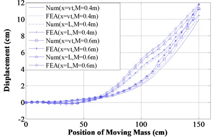
Fig. 8For v= 0.75vc km/h, L1,2,3= 0.4, 0.75, 1.1 m, α1,2= 0.6, 0.45, α3'= 0.6, θ3= 30°
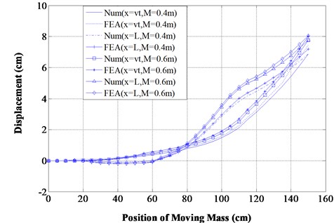
Fig. 9For v= 0.6vc km/h, L1,2,3= 0.4, 0.75, 1.1 m, α1'= 0.6, θ1= 30°, α2,3=0.45, 0.6
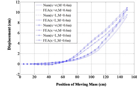
From Figs. 7-10 and Tables 2-4, it has been found that the beam deflection at different positions of the transit mass is more with the existence of open transverse cracks rather than inclined edge cracks. The response of the structure at the different time of the transit mass is also calculated and shown in Table 2 (Numerical and FEA) and Tables 3-4 (Numerical and experiments) for the comparison analysis. The percentage variation between the employed computational method and FEA is of maximum 6 % (Table 2) whereas that of experimental investigation is 7.5 % (Tables 3-4) which results in good agreements. From the various 3-D surface plots, similar observations are also made like 2-D graphs. It has been observed that the presence of open transverse cracks results in larger dynamic deflections of the structure than that of inclined edge cracks when subjected to transit mass.
Fig. 10For v= 0.75vc km/h, L1,2,3= 0.4, 0.75, 1.1 m, α1'= 0.6, θ1= 30°, α2,3= 0.45, 0.6
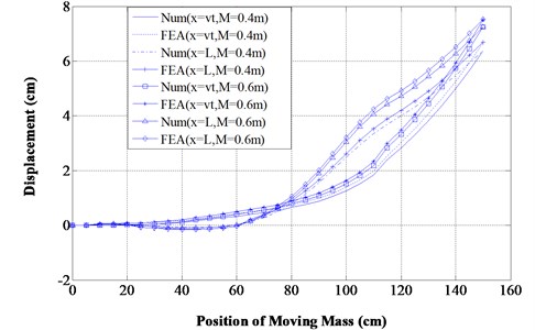
Table 2Comparison of results between Numerical and FEA works for Time (sec) ~Deflection (cm) at v=0.6vc km/h
30°, 0.6, 0.45, 0.6, 0.6 m | 30°, 0.45, 0.6, 0.45, 0.6 m | |||||||
Time | Num. | FEA | Num. | FEA | Num. | FEA | Num. | FEA |
0.0813 | –0.0703 | –0.0727 | 0.1505 | 0.1549 | –0.0689 | –0.7069 | 0.1505 | 0.1546 |
0.1423 | 0.9056 | 0.9429 | 0.6324 | 0.6559 | 0.8878 | 0.9163 | 0.6274 | 0.6495 |
0.2134 | 4.7725 | 4.9916 | 2.5633 | 2.6765 | 4.6643 | 4.8769 | 2.5644 | 2.6779 |
0.2947 | 9.7511 | 10.25 | 9.2658 | 9.7503 | 9.5556 | 10.035 | 9.0801 | 9.5409 |
Table 3Comparison of results between Numerical and Experimental works for Time (sec) ~Deflection (cm) at v=0.6vc km/h
0.6, 0.45, 30°, 0.6, 0.4 m | 30°, 0.6, 0.45, 0.6, 0.4 m | |||||||
Time | ||||||||
Num. | Expt. | Num. | Expt. | Num. | Expt. | Num. | Expt. | |
0.1138 | 0.2854 | 0.297 | 0.5341 | 0.5593 | 0.2816 | 0.2924 | 0.4557 | 0.4725 |
0.1545 | 2.28 | 2.4183 | 1.2383 | 1.3127 | 2.0129 | 2.137 | 1.048 | 1.0983 |
0.1951 | 4.4695 | 4.772 | 3.139 | 3.3368 | 3.9987 | 4.2282 | 2.8387 | 3.0141 |
0.2358 | 6.4058 | 6.8525 | 6.1272 | 6.5517 | 5.929 | 6.3506 | 5.6625 | 6.0834 |
Table 4Comparison of results between Numerical and Experimental works for Time (sec) ~Deflection (cm) at v=0.6vc km/h
55°, 0.6, 0.45, 0.4 m | 55°, 0.6, 0.45, 0.6 m | |||||||
Time | ||||||||
Num. | Expt. | Num. | Expt. | Num. | Expt. | Num. | Expt. | |
0.122 | 0.2742 | 0.2959 | 0.4018 | 0.4326 | 0.3364 | 0.3613 | 0.4935 | 0.5232 |
0.1626 | 1.6502 | 1.7531 | 0.9246 | 0.9725 | 2.0289 | 2.1927 | 1.1265 | 1.2075 |
0.2236 | 5.0404 | 5.392 | 3.0204 | 3.2194 | 5.9796 | 6.3451 | 3.5475 | 3.8264 |
0.2846 | 8.7301 | 9.2637 | 7.887 | 8.3425 | 9.9396 | 10.721 | 8.9839 | 9.4957 |
Table 5Comparison of frequencies in the presence of different types of cracks
0.6, 0.45 and 0.45, 30° | 0.6, 0.45, 30° and 0.45 | ||
Mode no | Frequency | Mode no | Frequency |
1 | 1.5977 | 1 | 1.6483 |
2 | 9.9905 | 2 | 10.384 |
3 | 28.3981 | 3 | 28.422 |
4 | 55.1260 | 4 | 55.727 |
5 | 95.152 | 5 | 95.828 |
Fig. 113-D surface plot for θ1,2= 30°, α1,2'= 0.6, 0.45, α3= 0.6, M= 0.4 m
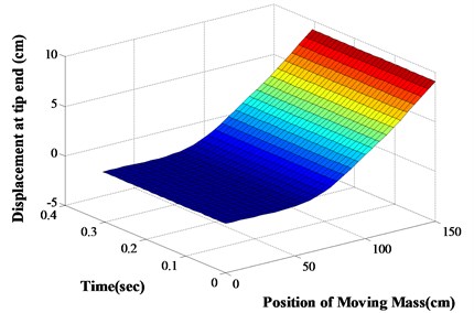
Fig. 123-D surface plot for α1,2= 0.6, 0.45, θ3= 30°, α3'= 0.6, M= 0.6 m
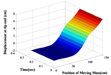
Fig. 133-D surface plot for θ1= 30°, α1'= 0.6, α2,3= 0.45, 0.6, M= 0.6 m
7. Conclusions
The dynamic responses of cracked cantilever beam with multiple different types of cracks subjected to transit mass are studied. The modelling of the cracks is done in FEA using the commercial ANSYS WORKBENCH 2015. The responses of the cracked structure with transit mass and speed are calculated using Runge-Kutta fourth order method. For the validation of the computational method; Numerical analysis followed by FEA and experimental investigations are carried out with different examples. The influences of different parameters affecting the dynamic response of the structure are investigated with parametric analysis. It has been observed that presence of open transverse cracks results in larger dynamic deflection of the structure than those of inclined edge cracks.
References
-
Lee H. P., Ng T. Y. Dynamic response of a cracked beam subjected to a moving load. Acta Mechanica, Vol. 106, 1994, p. 221-230.
-
Nandwana B. P., Maiti S. K. Modelling of vibration of beam in presence of inclined edge or internal crack for its possible detection based on frequency measurements. Engineering Fracture Mechanics, Vol. 58, Issue 3, 1997, p. 193-205.
-
Chaudhari T. D., Maiti S. K. Modelling of transverse vibration of beam of linearly variable depth with edge crack. Engineering Fracture Mechanics, Vol. 63, 1999, p. 425-445.
-
Ichikawa M., Miyakawa Y., Matsuda A. Vibration analysis of the continuous beam subjected to a moving mass. Journal of Sound and Vibration, Vol. 230, Issue 3, 2000, p. 493-506.
-
Wu J. J., Whittaker A. R., Cartmell M. P. Dynamic responses of structures to moving bodies using combined finite element and analytical methods. International Journal of Mechanical Sciences, Vol. 43, 2001, p. 2555-2579.
-
Mahmoud M. A., Abouzaid M. A. Dynamic response of a beam with a crack subject to a moving mass. Journal of Sound and Vibration, Vol. 256, Issue 4, 2002, p. 591-603.
-
Karuppaiah N., Deshpande P. S., Sujatha C., Ramamurti V. Vibration analysis in a light passenger vehicle by rigid body/finite element modelling. Advances in Vibration Engineering, Vol. 2, 2003, p. 106-120.
-
Bilello C., Bergman L. A. Vibration of damaged beams under a moving mass: theory and experimental validation. Journal of Sound and Vibration, Vol. 274, 2004, p. 567-582.
-
Law S. S., Zhu X. Q. Dynamic behaviour of damaged concrete bridge structures under moving vehicular loads. Engineering Structures, Vol. 26, 2004, p. 1279-1293.
-
Hsu Ming Hung Vibration analysis of edge-cracked beam on elastic foundation with axial loading using the differential quadrature method, computer. Methods in Applied Mechanics and Engineering, Vol. 194, 2005, p. 1-17.
-
Kwasniewski L., Li H., Wekezer J., Malachowski J. Finite element analysis of vehicle-bridge interaction. Finite Elements in Analysis and Design, Vol. 42, 2006, p. 950-959.
-
Nikkhoo A., Rofooei F. R., Shadnam M. R. Dynamic behaviour and modal control of beams under moving mass. Journal of Sound and Vibration, Vol. 306, 2007, p. 712-724.
-
Aydin Kamil Vibratory Characteristics of Euler-Bernoulli Beams with an Arbitrary Number of Cracks Subjected to axial load. Journal of Vibration and Control, Vol. 14, Issue 4, 2008, p. 485-510.
-
Ariaei A., Ziaei Rad S., Ghayour M. Vibration analysis of beams with open and breathing cracks subjected to moving masses. Journal of Sound and Vibration, Vol. 326, 2009, p. 709-724.
-
Behzad M., Ebrahimi A., Meghdari A. A continuous vibration theory for beams with vertical edge crack. Transaction B. Mechanical Engineering: Scientia Iranica, Vol. 17, Issue 3, 2010, p. 194-204.
-
Shafiei M., Khaji N. Analytical solutions for free and forced vibrations of a multiple cracked Timoshenko beam subject to a concentrated moving load. Acta Mechanica, Vol. 221, 2011, p. 79-97.
-
Dyniewicz B. Space–time finite element approach to general description of a moving inertial load. Finite Elements in Analysis and Design, Vol. 62, 2012, p. 8-17.
-
Zarfam R., Khaloo A. R. Review: vibration control of beams on elastic foundation under a moving vehicle and random lateral excitations. Journal of Sound and Vibration, Vol. 331, 2012, p. 1217-1232.
-
Behzada M., Ghadami A., Maghsoodi A., Hale Jack M. Vibration based algorithm for crack detection in cantilever beam containing two different types of cracks. Journal of Sound and Vibration, Vol. 332, 2013, p. 6312-6320.
-
Azam S. E., Mofid M., Afghani R. A. Dynamic response of Timoshenko beam under moving mass. Scientia Iranica A, Vol. 20, Issue 1, 2013, p. 50-56.
-
Cicirello A., Palmeri A. Static analysis of Euler-Bernoulli beams with multiple unilateral cracks under combined axial and transverse loads. International Journal of Solids and Structures, Vol. 51, 2014, p. 1020-1029.
-
Bakhtiari Nejad F., Khorram A., Rezaeian M. Analytical estimation of natural frequencies and mode shapes of a beam having two cracks. International Journal of Mechanical Sciences, Vol. 78, 2014, p. 193-202.
-
Zhong H., Yang M., Gao Z. Dynamic responses of prestressed bridge and vehicle through bridge–vehicle interaction analysis. Engineering Structures, Vol. 87, 2015, p. 116-125.
-
Nguyen Khoa Viet Dynamic analysis of cracked beam like bridge subjected to earthquake and moving vehicles. Advances in Structural Engineering, Vol. 18, Issue 1, 2015, p. 75-96.
-
Meirovitch L. Elements of Vibration Analysis. Second Edition, The McGraw-Hill Companies, New York, 2007.
-
Reddy J. N. An introduction to Finite Element Method. Third Edition, The McGraw-Hill Companies, New York, 2005.
