Abstract
It’s difficult to test repeatedly for large heavy-load bearings (LHLBs) with full-scale and real load due to complexity and costliness, so simulated identification on dynamic characteristics of 1750 MW nuclear generator bearing with diameter 800 mm and specific pressure 3.3 MPa is provided in this paper. The identification model of bearing dynamic characteristic is established, the calculating method of positive and negative dynamic problems is provided, and effects of signal disturbances on identification precision are analyzed. The results show that the LHLBs’ permitted displacement disturbance should not be over 5 μm and the permitted ratio of dynamic load and static load is about 1 %-2 %, which is different from common knowledge of 15 %-20 % for small light-load bearings. If identification error of the main stiffness and main damping coefficients is less than 5 %, the amplitude of periodical disturbance of the dynamic load and displacement signals should be less than 5 %. If identification error of the main damping coefficients is less than 10 %, the phase of these two signals should be less than 1°. The roundness error and rotation error of the large shaft should be eliminated.
1. Introduction
Nuclear energy is becoming one of the main new energies explored by countries in the world due to its economy and cleanness. China has been in the stage of fully developing nuclear power technology of kMW unit capacity, such as 1000 MW [1], 1550 MW [2] and 1750 MW [3]. As the promotion of unit capacity of nuclear generators, their bearings must be larger (diameter, over 800 mm) and heavier (specific pressure, , over 3.3 MPa) [4, 5]. The dynamic characteristics of large heavy-load bearings (LHLBs) directly determine equipment’s operation quality. Obtaining the LHLBs’ dynamic characteristic coefficients is meaningful to assess stability and fault diagnosis of rotor-bearing system.
The high identification precision on bearing dynamic characteristic is difficult in the dynamics field for a long period. From the excitation mode, identification methods are divided into stable excitation method and instantaneous excitation method. The sine excitation is the most frequent stable excitation [6]. In addition, single-frequency twice excitation method [7], time domain least mean method [8], pulse excitation method [9, 10], unbalanced quality method [11, 12] and impulse response method [13] are available.
As for identification precision, a test of an ellipse bearing with diameter 32 in and 1.21 MPa was reported, and the stiffness coefficients difference of calculated value and identified value (DCI) is about 40 % [14]. For a five-pad tilting-pad journal bearing with diameter 116.8 mm and maximum 1.034 MPa, the DCIs of stiffness and damping coefficients are 10 %-30 % and 10 %-40 % respectively [15]. For a tilting-pad journal bearing with diameter 110 mm and 0.3 MPa, the DCIs of the main stiffness and main damping coefficients are about 25 %-55 % and 20 %-35 % respectively [16]. The effect of load direction on non-nominal five-pad tilting-pad journal bearings and identification of dynamic coefficients was studied [17]. Most references have researched the small light-load or moderate-load bearings, but the applicability of their identification methods to the LHLBs needs to be demonstrated. The new difficulties produced by large heavy-load still have no answers. For example, what is the proper value of dynamic force and response for the LHLBs? How will signal disturbance affect identification precision for the LHLBs?
Test rig is the basic tool of identification on dynamic characteristic coefficients. Generally, test rig in the lab has small size and small load, which is difficult to satisfy LHLBs’ test requirement. On the one hand, it’s very difficult and expensive to conduct the test of full-scale bearings. On the other hand, the test environment is complicated and it is difficult to separate single factor for influence analysis. The similarity theory of dynamic characteristics has not been formed. Compared to the real test, simulation test can freely select factors, precisely set their size, and be repeatedly conducted without consumption of plentiful resources.
This work aims to propose simulated test method of LHLBs’ dynamic characteristics and reveal effect rules of signal disturbance on identification precision. The features of LHLBs’ dynamic characteristic test is analyzed in Section 2. Section 3 establishes the identification model. Section 4 gives the calculating method of the positive and negative problems. Section 5 gives the results and discussion. Finally, conclusion is given in Section 6.
2. The features of identification on the LHLBs’ dynamic characteristic
The main parameters of case bearing are similar to them of the bearings used in the 1750 MW nuclear power generator which has the world’s largest unit capacity. The bearing’s dynamic characteristic coefficients under different are given in Table 2 by solving the hydrodynamics model.
Table 1Physical parameters of the LHLBs
Parameters | Values | Parameters | Values |
Diameter (mm) | 800 | Rotational speed (r/min) | 1500 |
Width (mm) | 680 | Lubricating Oil | VG46 |
Unilateral back lash (mm) | 1.209 | Oil feed temperature (℃) | 40.0 |
Headspace (mm) | 0.52 | Specific pressure (MPa) | 1-3.3 |
Table 2Stiffness and damping coefficients of different pm (stiffness, ×109N/m; damping, ×107N.s/m)
(MPa) | ||||||||
0.5 | 0.15 | –0.80 | 0.98 | 1.80 | 0.50 | –0.41 | –0.41 | 1.91 |
1 | 0.47 | –0.64 | 1.57 | 2.62 | 0.60 | –0.06 | –0.06 | 2.45 |
1.5 | 0.76 | –0.34 | 2.41 | 3.97 | 0.65 | 0.25 | 0.25 | 3.22 |
2.0 | 1.14 | 0.04 | 3.50 | 5.79 | 0.74 | 0.64 | 0.64 | 4.37 |
2.4 | 1.50 | 0.16 | 4.52 | 7.55 | 0.85 | 1.04 | 1.04 | 5.59 |
2.8 | 1.71 | 0.57 | 5.38 | 10.08 | 0.79 | 1.10 | 1.10 | 6.35 |
3.0 | 1.86 | 0.78 | 5.92 | 11.52 | 0.80 | 1.19 | 1.19 | 6.87 |
3.3 | 2.09 | 1.02 | 6.77 | 13.68 | 0.84 | 1.36 | 1.36 | 7.82 |
3.5 | 2.24 | 1.16 | 7.39 | 15.28 | 0.88 | 1.50 | 1.50 | 8.56 |
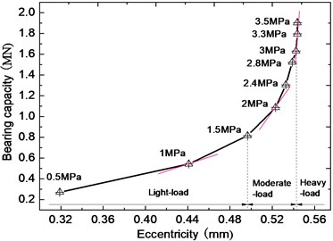
The bearing performance is sensitive to the displacement disturbance under heavy-load as shown in Fig. 1. With increase of load, the sensitivity of liquid force to eccentricity continuously increases. The load is divided into light-load (1.5 MPa), moderate-load (1.5 MPa 3 MPa) and heavy- load ( 3 MPa) according to the current load of turbine or generator bearings. When displacement disturbance 10 μm occurs around eccentricity 0.44 mm ( 1 MPa), the change of is about 10.3 %. When displacement disturbance 10 μm occurs around eccentricity 0.54 mm ( 3.3 MPa), is over 4 MPa. At this time, the bearings dynamic characteristics have significantly changed. If the test values are compared with the original performance values, it will lead to tremendous error.
Fig. 1Liquid force of eccentricity (or specific pressures)
For the LHLBs’ dynamic characteristic test, what’s the proper displacement disturbance? 10 μm is required in dynamic characteristic test of general bearings [18]. The change of the main stiffness and main damping coefficients is about 40 % under disturbance 10 μm as shown in Table 3, and the maximum change of crossing coefficients reaches 71 %. Assuming that the permitted change of dynamic characteristic coefficients is less than 20 %, the permitted displacement disturbance should not be over 5 μm. The SNR will be very low in such small signal, so it proposes higher requirements for test precision [19]. At the same time, the rotation error and shape error of the rotating shaft should be considered.
Table 3Relative difference of the LHLBs’ dynamic characteristic with front-to-back interfering (3.3 MPa)
Disturbance (μm) | Relative difference (%) | |||||||
3 | 5.0 | 4.8 | 5.01 | 5.0 | 5.0 | 8.2 | 8.2 | 5.6 |
5 | 12.3 | 17.8 | 14.8 | 17.2 | 9.75 | 19.8 | 19.8 | 16.0 |
10 | 38.2 | 71.2 | 42.0 | 47.1 | 30.07 | 56.9 | 56.9 | 41.2 |
15 | 53.4 | 147.7 | 63.6 | 85.4 | 25.53 | 58.5 | 58.5 | 55.8 |
3. Identification model
As shown in Fig. 2, the test bearing is suspended on the shaft and the excitation is directly imposed onto test bearing [20]. Because the disturbance factors of this test rig are relatively less, the identification model of LHLBs’ dynamic characteristic coefficients are established based on this test rig.
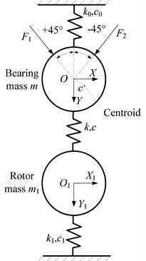
The linear assumption of liquid force is introduced firstly. Assuming that the dynamic load passes bearing’s geometric center and the bearing under plane motion, as shown in Figure 3, the dynamic equations of test bearing system are given as:
where and are dynamic load. (, ) is absolute displacement of test bearing to static balance position. (, ) is absolute displacement of shaft. (, ) is displacement of test bearing center to shaft center. and are mass of test bearing and shaft respectively. and are the connection stiffness and damping coefficients. and are the stiffness and damping coefficients of support bearing. and are the stiffness and damping coefficients matrix of test bearing.
Fig. 2Schematic diagram of the test rig 1 – shaft, 2 – support bearing 1, 3 – experiment module, 4 – chain, 5 – test bearing, 6 – bellows, 7 – support bearing 2, 8 – platform, 9 – damping base
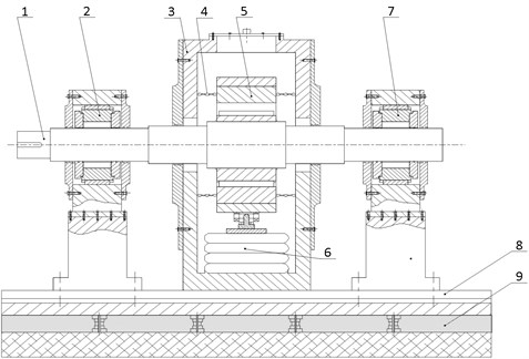
Fig. 3Dynamic model of test bearing system
Fourier transforming Eq. (1) to the equation of frequency-domain:
The dual-frequency excitation method, which means sine dynamic load in two directions and two frequencies ( and ) are simultaneously imposed onto test bearing. Displacement, mass, connection stiffness and damping coefficients are known, 8 linear equations can be established. and can be obtained by solving the equations.
4. Simulated test method
The simulated test is a process of combining solving the positive and negative problems. The positive problem means obtaining system responses based on load and system characteristics. The negative problem means identifying characteristic parameters based on load and responses.
4.1. Positive problems
The calculating method of positive problem is solving Eq. (2) by using stiffness and damping coefficients and two-channel dynamic loads, and obtaining relative displacement and absolute displacement. Firstly, and in +45° direction are used. The Eq. (2) is divided into real part and virtual part to obtain linear equations:
where:
where the matrix and are known, and is an 8×8 matrix. The ellipsis of Eq. (4) means connecting a same row. The values of the matrix elements are known. To solve matrix equation , obtaining , , and .
Secondly, to solve Eq. (2) using and in –45° direction, obtaining , , and .
4.2. Negative problems
The calculating method of negative problem is solving Eq. (2) by using displacements and two-channel dynamic loads, and identifying stiffness and damping coefficients. The Eq. (2) is divided into real part and virtual part to obtain linear equations:
where:
where matrix and are known. To solve matrix equation , obtaining bearing dynamic characteristic coefficients.
4.3. Adding method of disturbance factors
In fact, the matrix elements include errors in test. These initial errors will be propagated along calculating process, it finally affects identifying results. It’s necessary to know the effect rule of the disturbance to identification precision, which will provide evidence for finding the method to control disturbance.
Four disturbance factors are studied:
a) Periodical disturbance can be added by adding disturbances into amplitude and phase of dynamic load and response in frequency-domain:
where (, ) and (, ) are amplitude and phase under before to after interfering respectively. and are relative disturbance of amplitude (%) and absolute disturbance of phase (°) respectively.
b) Random disturbance can be added in time-domain:
The first item in the right-hand of Eq. (8) is standard signal. The second item is random disturbance. means disturbance proportion. The function will generate random number matrix of normal distribution with 0 mean and 1 variance in the MATLAB. This random disturbance has random effect on the amplitude and phase, so the identification error should be statistic analyzed. The number of calculating is 1000.
c) Disturbance of large shaft. The disturbance of large shaft includes roundness error and rotation error. Firstly, the disturbance functions are constructed, the discrete roundness error (unit: μm):
where is amplitude. is sample number in one turn.
The discrete rotation error (unit: μm):
where the first and second item in its right hand are the displacements related to external excitation ( and are excitation frequency). The third item is the displacement related to rotor self- excitation. is rotational speed.
The relative displacement of test bearing after adding disturbance:
where the disturbance:
where: , .
4.4. Flow of simulated test and accuracy assessment
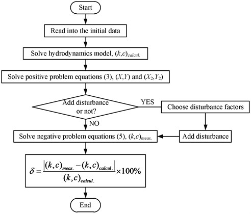
Firstly, get theoretical values of bearing’s stiffness and damping coefficients . by solving the hydrodynamics model. Then solve the positive problem Eq. (3) to get response. Thirdly, add disturbances to force or displacement as shown in Eq. (7-12), and get identification values of bearing’s stiffness and damping coefficients by solving the negative problem Eq. (5). Compare the identification values with the theoretical values, and analyze the error at last. The flowchart of simulated test is shown in Fig. 4. Where is relative difference.
According to the calculation principle of positive and negative problems, if there is no error in calculation process, and no human interference, the identification results of dynamic coefficients should be completely equal in the given values. But in fact, decimals will be omitted in numerical calculation, which will result in a small difference. As shown in Table 4, identification error of the main stiffness and main damping coefficients is less than 0.25 %, and that of the cross term is less than 0.32 %. This shows that the matrix calculation accuracy is very high.
In addition, it’s important to analyze ill- condition of the test equations after giving values of the dynamic characteristic coefficients. Morbid recognition of Eqs. (6) is conducted to get the sensitivity of solution to disturbance of initial value. Condition number is used as an index to measure morbid degree. If condition number is relatively small, the equations is good. On the contrary, if condition number is relatively large, the equations is ill, and larger the condition number is, more serious ill condition is. In Eqs. (6), the 2 norm of the matrix and its condition number is 1.9×10⁻⁴ and 41.1 respectively. According to the mathematical theory [21], condition number is less than 100, which indicates that Eq. (6) is in good condition.
Fig. 4The flowchart of simulated test
5. Results and discussion
5.1. Simulate test error with disturbance
5.1.1. Size and disturbance of dynamic load
Response is controlled by dynamic load directly, so the size of dynamic load needs to be restricted. means the ratio of dynamic load amplitude to static load. In test of general bearing dynamic characteristic, is 10 %-20 % [19]. Because the LHLBs’ permitted response is smaller, this paper guesses that of the LHLBs may vary.
Taking a small ellipse bearing with diameter 100 mm for example, its gap ratio and ratio is same as them of the large one in Table 1. The relative displacement in vertical direction under different can be obtained by solving positive problem equations, as shown in Fig. 5. For light load (1 MPa) and moderate-load (2.4 MPa), if the permitted response is 5 μm-10 μm, the permitted value of γ is about 17 %-34 %. For heavy-load (3.3 MPa), if the permitted response is 3 μm-5 μm, the permitted value of is about 10 %-20 %. For the ellipse bearing with diameter 800 mm, if the permitted response under light load, moderate load and heavy load are 10 μm-15 μm, 5 μm-10 μm and 3 μm-5 μm, the permitted value of are 5 %-8 %, 2 %-4 % and 1 %-2 % respectively. Compared to the light- load, under heavy load is smaller and which will reduce with increase of bearing diameter.
The disturbance is added on amplitude and phase of dynamic load shown as Eq. (7). The disturbances of two excitation signals are identical. The crossing damping coefficients have small effect on dynamics computing of rotor-bearing system, so this paper will mainly discuss the main stiffness and main damping coefficients.
Fig. 5Displacement in vertical direction of different γ
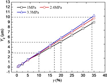
a) Diameter 100 mm
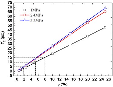
b) Diameter 800 mm
As shown in Table 4, with increase of amplitude disturbance, identification error of the stiffness and damping coefficients increases. Except crossing damping coefficients, the size of identification error keeps analogous with amplitude disturbance. If identification error of the main stiffness and main damping coefficients is less than 5 %, the amplitude disturbance of dynamic load should be less than 5 %. Phase disturbance has smaller effect on the stiffness coefficients and bigger effect on the damping coefficients. As for the LHLBs, if identification error of the main damping is less than 18 %, phase disturbance of dynamic load should be less than 1°. When the amplitude and phase disturbances coexist, the effect on identification precision will add linearly of effects under two separate disturbances.
Table 4Identification precision with disturbance of dynamic load changing
Amplitude disturbance (%) | Phase disturbance (°) | Relative error (%) | |||||||
0 | 0 | 0.07 | 0.23 | 0.19 | 0.19 | 0.09 | 0.15 | 0.32 | 0.25 |
3 | 0 | 2.70 | 2.76 | 3.39 | 3.76 | 3.32 | 3.39 | 5.09 | 4.38 |
5 | 0 | 4.65 | 4.64 | 5.38 | 5.75 | 5.50 | 5.40 | 8.19 | 6.77 |
10 | 0 | 9.52 | 9.32 | 10.34 | 10.73 | 10.97 | 10.43 | 15.95 | 12.75 |
0 | 1 | 0.44 | 0.53 | 0.42 | 0.68 | 13.03 | 7.22 | 48.17 | 18.27 |
0 | 2 | 0.68 | 1.04 | 0.40 | 0.55 | 25.99 | 14.84 | 95.85 | 35.72 |
0 | 3 | 0.96 | 1.57 | 0.35 | 0.40 | 38.90 | 22.48 | 143.45 | 53.12 |
3 | 1 | 2.48 | 2.27 | 3.40 | 3.66 | 16.70 | 4.43 | 54.26 | 22.39 |
5 | 1 | 4.42 | 4.13 | 5.39 | 5.65 | 19.15 | 2.57 | 58.32 | 25.13 |
5.1.2. Periodical disturbance of displacement
The periodical disturbance is added on absolute displacement and relative displacement simultaneously shown as Eq. (7). As shown in Table 6, assuming that identification error of the stiffness and main damping coefficients is less than 5 %, amplitude disturbance should be less than 5 %. And if identification error of the main damping coefficients is less than 10 %, phase disturbance should be less than 1°.
5.1.3. Random disturbance of displacement
The random disturbance is added on displacement shown as Eq. (8). As shown in Table 5, the effect of same disturbance on the damping coefficients is bigger than it on the stiffness coefficients, because although the random disturbance of displacement signals has limited effect on amplitude in frequency-domain, but it generates comparatively large effect on phase. Moreover, identification error of the stiffness and main damping coefficients in heavy-load is much bigger than it in light-load. If the disturbance value is 10 %, compared to 1 MPa, identification error of the main stiffness coefficients is 2-3 times bigger under 3.3 MPa, and the error difference of the main damping coefficients under two loads is about one order of magnitude. So, the random disturbance is the key factor in dynamic characteristic test of LHLBs and should be reduced in each step. For this case, if identification error of the main stiffness coefficients is less than 5 %, the random disturbance of displacement signals in time-domain should be less than 5 %.
Table 5Identification precision with periodical disturbance of displacement changing
Amplitude disturbance (%) | Phase disturbance (°) | Relative error (%) | |||||||
3 | 0 | 3.06 | 2.77 | 2.49 | 2.14 | 3.15 | 2.56 | 4.09 | 2.70 |
5 | 0 | 4.86 | 4.51 | 4.32 | 3.98 | 5.17 | 4.42 | 6.96 | 4.91 |
10 | 0 | 9.07 | 8.56 | 8.63 | 8.30 | 9.91 | 8.77 | 13.68 | 10.09 |
0 | 0.5 | 0.12 | 0.18 | 0.39 | 0.80 | 6.47 | 4.15 | 23.46 | 7.97 |
0 | 1 | 0.03 | 0.41 | 0.37 | 0.83 | 12.99 | 7.93 | 47.36 | 16.74 |
0 | 2 | 0.13 | 0.83 | 0.29 | 0.86 | 26.05 | 15.46 | 95.18 | 34.29 |
0 | 3 | 0.25 | 1.23 | 0.19 | 0.86 | 39.13 | 22.95 | 143.02 | 51.88 |
3 | 1 | 2.87 | 2.33 | 2.53 | 2.08 | 15.80 | 4.78 | 50.49 | 19.71 |
5 | 1 | 4.68 | 4.07 | 4.36 | 3.92 | 17.58 | 2.78 | 52.47 | 21.60 |
10 | 2 | 8.76 | 7.76 | 8.73 | 8.21 | 33.62 | 4.94 | 100.60 | 41.98 |
Table 6Identification precision with random disturbance of displacement under two loads
(MPa) | Disturbance (%) | Relative error (%) | |||||||
1 | 3 | 0.57 | 0.42 | 1.63 | 0.90 | 2.86 | 63.12 | 436.23 | 33.30 |
5 | 0.81 | 0.94 | 2.34 | 3.31 | 9.42 | 95.63 | 804.59 | 26.31 | |
7 | 0.67 | 0.67 | 1.77 | 5.29 | 10.85 | 245.58 | 905.00 | 81.52 | |
10 | 2.88 | 2.03 | 9.01 | 8.23 | 5.94 | 94.07 | 780.12 | 27.42 | |
3.3 | 3 | 2.42 | 8.73 | 3.48 | 3.11 | 54.66 | 67.58 | 175.51 | 62.48 |
5 | 5.12 | 15.57 | 8.45 | 5.96 | 254.94 | 433.65 | 878.00 | 420.05 | |
7 | 5.84 | 33.33 | 10.40 | 15.47 | 113.83 | 258.33 | 411.20 | 255.05 | |
10 | 6.20 | 36.30 | 9.53 | 13.88 | 206.69 | 333.19 | 732.93 | 333.93 | |
5.1.4. Roundness error and rotation error of large shaft
The simulated test results are shown in Table 7-Table 10. The values of rotation error and roundness error are obtained by using the circular graphical method [22]. For Table 7 and Table 8, compared to light-load, the same rotation error has bigger effect on identification precision under heavy-load. The identification error of the stiffness coefficients under heavy-load is about 25 times than it under light-load. The effect of the rotation error caused by the external excitation on the damping coefficients is much bigger than it on the stiffness coefficients. So, the rotation error caused by the external exception should be eliminated before solving Eq. (2) in LHLBs’ test.
Table 9 shows the effect of rotation error caused by self-excitation under heavy-load, and the effect is mutable. When the rotation error is less than about 11.74 μm, the effect on identification precision is less than 0.3 %. When it reaches 11.88 μm, the precision will suddenly deteriorate, which may be caused from resonance of the rotor system. The effect of the roundness error is similar as shown in Table 10. When the roundness error is at about 23.3 μm, the identification error will dramatically deteriorate. When diameter is 400-500 mm and grade of tolerance is 7, the roundness tolerance is 20 μm according to the standard. The roundness tolerance of case bearing with diameter 800 mm will exceed 20 μm, so its roundness error should be considered. For LHLBs, disturbance of large shaft should be eliminated by using multi-point method, multi-step method and so on [23].
Table 7Identification precision with rotation error caused by external exception (pm= 1 MPa)
Rotation error (μm) | Relative error (%) | |||||||||
0 | 0 | 0 | 0.12 | 0.16 | 0.02 | 0.26 | 0.01 | 1.36 | 1.56 | 0.22 |
0.05 | 0.05 | 0.14 | 0.04 | 0.11 | 0.10 | 0.39 | 0.33 | 8.81 | 92.92 | 3.74 |
0.1 | 0.1 | 0.28 | 0.04 | 0.07 | 0.24 | 0.51 | 0.65 | 16.23 | 184.09 | 7.72 |
0.15 | 0.15 | 0.42 | 0.11 | 0.02 | 0.39 | 0.62 | 0.97 | 23.61 | 275.04 | 11.70 |
0.2 | 0.2 | 0.57 | 0.19 | 0.03 | 0.54 | 0.72 | 1.28 | 30.96 | 365.75 | 15.70 |
Table 8Identification precision with rotation error caused by external exception (pm= 3.3 MPa)
Rotation error (μm) | Relative error (%) | |||||||||
0 | 0 | 0 | 0.22 | 0.05 | 0.41 | 0.77 | 0.04 | 0.37 | 0.43 | 0.79 |
0.05 | 0.05 | 0.14 | 0.51 | 0.00 | 1.30 | 0.22 | 44.50 | 57.78 | 179.29 | 65.98 |
0.1 | 0.1 | 0.28 | 1.50 | 1.91 | 3.58 | 1.43 | 86.99 | 114.25 | 349.04 | 130.04 |
0.15 | 0.15 | 0.42 | 2.83 | 5.33 | 6.55 | 3.38 | 126.46 | 167.96 | 505.72 | 190.60 |
0.2 | 0.2 | 0.57 | 4.45 | 10.04 | 10.06 | 5.93 | 162.28 | 217.91 | 646.87 | 246.57 |
Table 9Identification precision with rotation error caused by self-excitation (pm= 3.3 MPa)
Rotation error (μm) | Relative error (%) | ||||||||
8.0 | 11.31 | 0.08 | 0.23 | 0.19 | 0.20 | 0.11 | 0.18 | 0.06 | 0.15 |
8.3 | 11.74 | 0.08 | 0.23 | 0.19 | 0.20 | 0.11 | 0.18 | 0.06 | 0.15 |
8.4 | 11.88 | 41.64 | 137.10 | 109.26 | 89.43 | 405.83 | 458.13 | 328.59 | 155.89 |
9.1 | 12.67 | 42.75 | 141.18 | 109.59 | 89.72 | 379.59 | 432.25 | 312.29 | 151.37 |
Table 10Identification precision with roundness error (pm= 3.3 MPa)
Roundness error (μm) | Relative error (%) | ||||||||
0.5 | 2.0 | 0.08 | 0.24 | 0.19 | 0.20 | 0.02 | 0.07 | 0.46 | 0.04 |
5.0 | 15.9 | 0.09 | 0.34 | 0.17 | 0.22 | 0.66 | 0.74 | 7.51 | 2.56 |
8.0 | 22.0 | 0.10 | 0.40 | 0.16 | 0.23 | 1.11 | 1.27 | 12.20 | 4.25 |
8.7 | 23.3 | 26.93 | 81.29 | 109.87 | 90.17 | 892.90 | 944.30 | 160.49 | 107.73 |
9.0 | 23.9 | 27.62 | 83.80 | 110.08 | 90.35 | 877.95 | 929.61 | 151.19 | 105.15 |
6. Conclusions
As promotion of unit capacity of nuclear generators, their bearings are becoming larger and heavier, new difficulties to LHLBs’ dynamic characteristic test should be emphasized in the identification method and test system’s design. Simulated test on dynamic characteristics of the LHLBs is investigated in this work. Conclusions are as follows:
1) The diameter and load affect the permitted response and dynamic load. For large bearings with diameter 800 mm, if the permitted response under heavy-load is 3 μm–5 μm, the ratio of dynamic load and static load is 1 %–2 %, which is different from common knowledge of 15 %–20 % for small light-load bearings.
2) For the large bearing with 3.3 MPa, if identification error of the main stiffness and main damping coefficients is less than 5 %, the amplitude of periodical disturbance of dynamic load and displacement signals should be less than 5 %. If identification error of the main damping coefficients is less than 10 %, the phase of these two signals should be less than 1°. Identification precision of the damping coefficients is very sensitive to the random disturbance of signals.
3) Comparing to light-load, the same rotation error caused by external excitation has bigger effect on identification precision under heavy-load. The effect of rotation error caused by self-excitation and roundness error to identification precision has mutant character, and these errors of large shaft should be eliminated.
References
-
Gong H., Zan Y., Peng C., Xi Z., Zhang Z., Wang Y., He Y., Huang Y. Progress of experimental research on nuclear safety in NPIC. Kerntechnik, Vol. 81, Issue 2, 2016, p. 125-133.
-
Li Y. Q., Chang H. J., Ye Z. S., Fang F. F., Shi Y., Yang K., Cui M. T. Analyses of ACME integral test results on CAP1400 small-break loss of-coolant-accident transient. Progress in Nuclear Energy, Vol. 88, 2016, p. 375-397.
-
Zhang F., Ouyang W., Hong H. L., Guan Y. S., Yuan X. Y., Dong G. N. Experimental study on pad temperature and film thickness of tilting-pad journal bearings with an elastic-pivot pad. Tribology International, Vol. 88, 2015, p. 228-235.
-
Chauhan A., Sehgal R., Sharma R. K. Thermohydrodynamic analysis of elliptical journal bearing with different grade oils. Tribology International, Vol. 43, Issue 11, 2010, p. 1970-1977.
-
Singh D. V., Sinhasan R., Prabhakaran Nair K. Elastothermohydrodynamic effects in elliptical bearing. Tribology International, Vol. 22, Issue 1, 1989, p. 43-49.
-
Glienicke J. Experimental investigation of the stiffness and damping coefficients of tubing bearings and their application to instability prediction. Journal Bearings for Reciprocation and Turbo Machinery, IME Symposium in Nottingham, 1966, p. 122-135.
-
Sudheer Kumar Reddy D., Swarnamani S., Prabhu B. S. Experimental investigation on the performance characteristics of tilting-pad journal bearings for small L/D ratios. Wear, Vol. 212, 1997, p. 33-40.
-
Zhao S. X., Zhou H., Meng G., Zhu J. Experimental identification of linear oil-film coefficients using least-mean-square method in time domain. Journal of Sound and Vibration, Vol. 287, Issues 4-5, 2005, p. 809-825.
-
Hu H., Jiang G. D. Identification of oil film coefficients of large journal bearings on a full scale journal bearing test rig. Tribology International, Vol. 30, Issue 11, 1997, p. 789-793.
-
Qiu Z. L., Tieu A. K. Identification of sixteen force coefficients of two journal bearings from impulse responses. Wear, Vol. 212, Issue 2, 1997, p. 206-212.
-
Tiwari R., Chakravarthy V. Simultaneous estimation of the residual unbalance and bearing dynamic parameters from the experimental data in a rotor-bearing system. Mechanism and Machine Theory, Vol. 44, Issue 4, 2009, p. 792-812.
-
Tieu A. K., Qiu Z. L. Identification of sixteen force coefficients of two journal bearings from experimental unbalance responses. Wear, Vol. 177, Issue 1, 1994, p. 63-69.
-
Brenkacz L. Identification of stiffness, damping and mass coefficients of rotor-bearing system using impulse response method. Journal of Vibroengineering, Vol. 17, Issue 5, 2015, p. 2272-2282.
-
Hisa S., Matsuura T., Someya T. Experiments on the dynamic characteristics of large scale journal bearings. Proceedings of IMechE – International Conference on Vibrations in Rotating Machinery, C284/80, 1980, p. 223-230.
-
Al-Ghasem A. M., Childs D. W. Rotordynamic coefficients measurements versus predictions for a high-speed flexure-pivot tilting-pad bearing (load-between-pad configuration). Transactions of the ASME, Vol. 128, Issue 4, 2006, p. 896-906.
-
Delgado A., Vannini G., Drexel B. E. M., Naldi L. Identification and prediction of force coefficients in a five-pad and four-pad tilting pad bearing for load-on-pad and load-between-pad configurations. Journal of Engineering for Gas Turbines and Power, Vol. 133, Issue 9, 2011, p. 092503.
-
Dang P. V., Chatterton S., Pennacchi P., Vania A. Effect of the load direction on non-nominal five-pad tilting-pad journal bearings. Tribology International, Vol. 98, 2016, p. 197-211.
-
Fritzen C. P. Identification of mass, damping and stiffness matrices of mechanical system. ASME Journal of Vibration, Acoustics, Stress and Reliability in Design, Vol. 108, Issue 1, 1986, p. 9-16.
-
Dimond T. W., Sheth P. N., Allaire P. E., He M. Identification methods and test results for tilting pad and fixed geometry journal bearing dynamic coefficients – a review. Shock and Vibration, Vol. 16, Issue 1, 2009, p. 13-43.
-
Tschoepe D. P., Childs D. W. Measurements versus predictions for the static and dynamic characteristics of a four-pad, rocker-pivot, tilting-pad journal bearing. ASME Journal of Engineering for Gas Turbines and Power, Vol. 136, Issue 5, 2014, p. 052501.
-
Brezinski C., Redivo-Zaglia M., Rodriguez G., Seatzu S. Multi-parameter regularization techniques for ill-conditioned linear systems. Numerische Mathematik, Vol. 94, Issue 2, 2003, p. 203-228.
-
Shi S. Y., Lin J., Wang X. F., Zhao M. A hybrid three-probe method for measuring the roundness error and the spindle error. Precision Engineering – Journal of the International Societies for Precision Engineering and Nanotechnology, Vol. 45, 2016, p. 403-413.
-
Marsh E., Couey J., Vallance R. Nanometer-level comparison of three spindle error motion separation techniques. Transactions of the ASME, Vol. 128, Issue 1, 2006, p. 180-187.
About this article
This work was supported by the Fundamental Research Funds for the Central Universities (WUT: 2016IVA021) and the National Basic Research Program of China (2015CB057303).
