Abstract
The stability and bifurcation of a flexible rod-fastening rotor bearing system with a transverse open crack in a fastening rod are investigated. The nonlinear dynamic model of a cracked rod-fastening rotor system is established based on the finite element method. A methodology is introduced where shooting method, path-following technique, and Floquet theory are combined for determining the periodic solutions and stability margins of the system. The effects of crack depth and mass eccentricities on the system are studied by numerical simulations. Results show the system stability will reduce due to the presence of crack, two saddlebacks occur on the periodic-doubling borderline whose bottom location corresponds to the two resonant peak of bearing node, and effects of the crack and mass eccentricity play a dominant position in different conditions respectively. Comparisons between the cracked rotor system and the intact ones referred in the literature indicate that some special characteristics of cracked rod-fastening rotor system in motion orbits and frequency components can be used to detect the presence of crack and its depth.
Highlights
- The model of rod-fastening rotor system with a crack in a fastening rod are developed.
- The presence of crack in a rod leads to the reduction of the system stability.
- Two resonant peak can be found in the cracked rod-fastening rotor system.
- The effects of crack play a dominant position for balanced rod-fastening rotor system.
- Periodic-doubling bifurcation early occurs to cracked system for small mass unbalance.
1. Introduction
The stability and bifurcation of cracked rotor bearing system have always been the focus of attention. The fatigue crack is a very typical failure of rotor bearing system, which always causes great damage to some extent. It is essential to find out the dynamic characteristics of rotor system at the initial stage of crack and take appropriate measures in time to avoid some serious losses, especially for complex rod-fastening rotor bearing system. Rod-fastening rotor bearing system is a kind of typical structural pattern of combined rotor system in which always more than two disks are fastened by one central rod or several circumferentially distributed rods. It widely exists in gas turbine, aircraft engine and power generation which occupy a dominant position in modern heavy industrial equipment. When there is a crack in a rotor spindle, a fastening rod or a disk of the rod-fastening rotor system, the dynamic behaviours of the system will become complicated compared with Jeffcott rotor system and the destructive effect is even more catastrophic in a sort of way.
During the past several decades, for the dynamic behaviours of cracked rotor bearing system, many studies have been carried out theoretically or experimentally [1-14]. Most of their studies based on the Jeffcott rotor system and rotor shaft crack. Meanwhile, the dynamics of cracked rotor system with different structures have been attracted more attentions gradually and many of them didn’t contain the fastening rods. The effects of a transverse crack on the dynamics of a multi-rotor, multi-bearing system [15] or a fragment of the shaft of constant cross-section system with considering the coupled torsional and bending vibrations [16] are carried out, respectively. AL-Shudeifat [17, 18] obtained the time-varying stiffness of cracked rotor and investigated the stability of cracked rotor bearing system with two disks. Han and Chu [19] investigated the effect of a transverse crack on the parametric instability of a rotor-bearing system with two disks, and one of them is asymmetric. Nagata and Inoue [20] developed an analytical method to detect the vibration behaviours of cracked rotor bearing system with three disks. Bala Murugan [21] conducted considerable analyses of cracked rotor bearing system with multi-disk and variable cross section. Their studies provided many useful strategies for treating the problem of cracked rotor bearing system especially for complex rotor systems. Whether it is the Jeffcott rotor or other complex rotor system mentioned above, they are not attached to any fastening rod. It is this typical structure between rod-fastening rotor system and non-rod fastening rotor system that makes some differences in dynamic behaviours. For non-rod-fastening rotor system, the corresponding dynamic models are developed based on condition that the system gravity occupies a domain position. While this assumption of dominant gravity can’t directly be used for the rod-fastening rotor system because the big tension stress of fastening rod far outweighs the compressive stress and additional bending stress caused by the system gravity. Meanwhile, it is worth noting that this will lead to this kind of rod-fastening rotor system working in an opening crack mode mostly. Besides, because of the alternating stress of system, a fatigue crack either in a rod or a disk become easy to appear on the direct contact position between the fastening rod and disk as well as in the vicinity of this position. While the crack is on shaft or fastening rod, the dynamic behaviours especially the nonlinear dynamic behaviours of system have not gained sufficient attentions.
In order to reflect the dynamic behaviours of the rod-fastening rotor bearing system with cracks and consider the big tension stress effects of the fastening rod, the nonlinear dynamic model of the system with a transverse open crack in a fastening rod is developed based on the finite element method. A combined technique is employed to investigate the system stability and bifurcation.
2. Modeling of cracked rod-fastening rotor bearing system
2.1. Dynamic modeling of a fastening rod with no crack
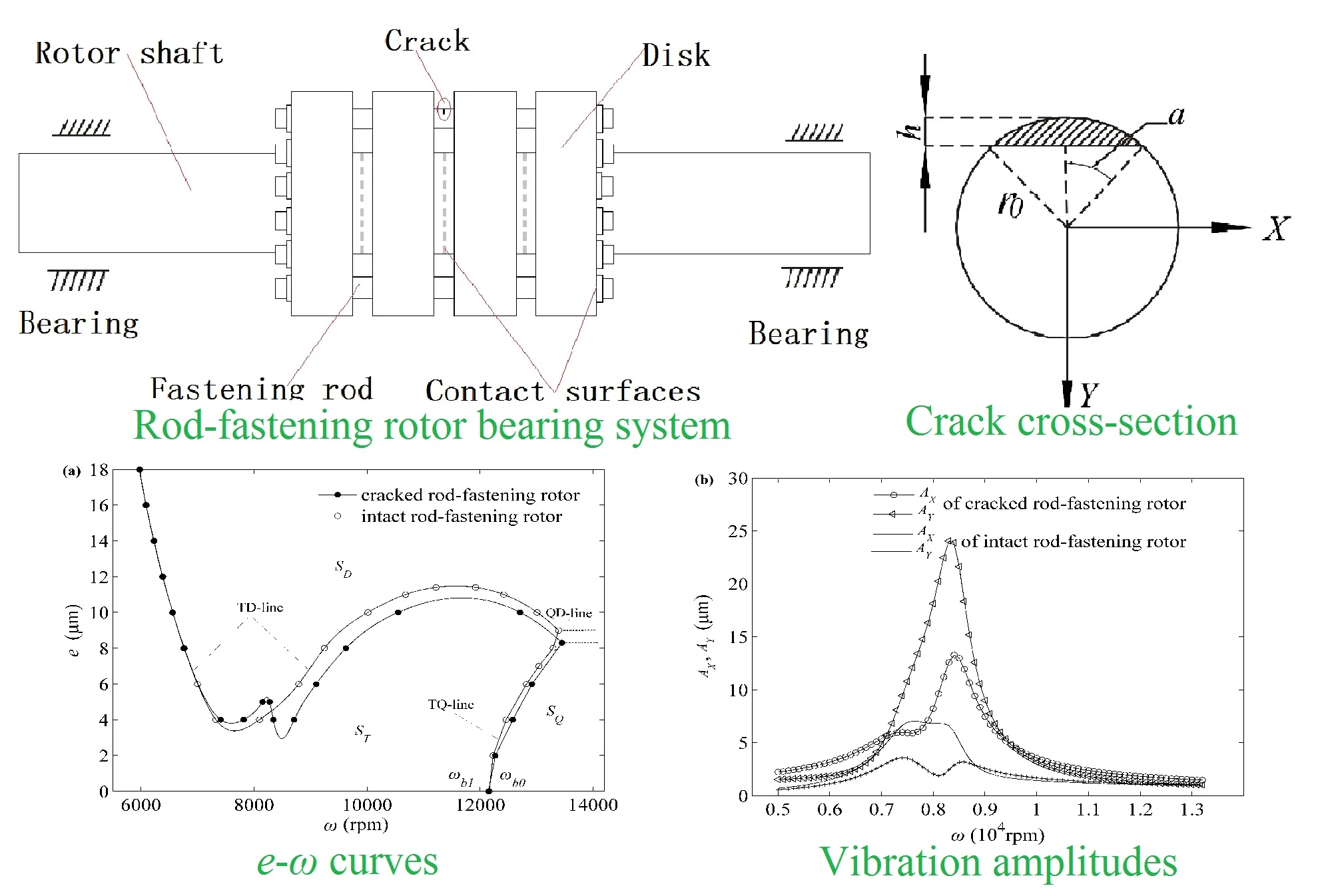
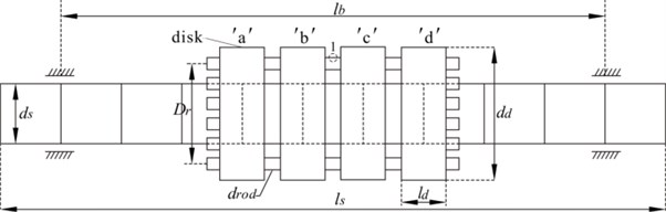
The flexible rod-fastening rotor bearing system is depicted in Fig. 1. Four rigid disks, mounted on the rotor shaft, are fastened by several circumferentially distributed rods and the rotor is supported by two radial cylindrical bearings. The rotor shaft is discretized by using the finite element method with Timoshenko beam, and then the attached fastening rod are modeled as spring element with no mass. The notations as illustrated in Fig. 1 and other essential physical parameters are given in Table 1.
Fig. 1Flexible rod-fastening rotor bearing system. The labels ‘a’, ‘b’, ‘c’, and ‘d’ denote the four disks for distinguishing
The modeling of a fastening rod with no crack as explained in [22, 23] is briefly presented. The instantaneous tension of each rod as shown in Fig. 1 is determined by the position of rod both ending points, which are located on the corresponding disks ‘a’ and ‘d’. According to [22, 23], the elongation and axial force of th fastening rod due to the vibration of rotor system can be expressed approximately as follows:
where , , ,and are the tilting angles. is the rotating speed of the rotor. is the radius of distributed circumference of the n rods. where is the mounted angle of th fastening rod and this rods are distributed averagely with (1, 2, …, , ≥ 3). , , and is the pre-tightening force, the original length and the cross-section area of the fastening rod, respectively.
Table 1Material properties and geometric parameters of rotor system
Parameters | values | Parameters | values |
Mass density, (kg.m-3) | 7800 | Mass eccentricities of disks, (m) | 0-2×10⁻⁵ |
Young's modulus, (GPa) | 210 | Diameter of rods, (m) | 0.01 |
Poisson ratio, | 0.3 | Number of rods, | 12 |
Diameter of shaft, (m) | 0.08 | Diameter of circumference of rods, (m) | 0.12 |
Length of shaft, (m) | 1.1 | Pre-tightening load of each rod, (N) | 15700 |
Diameter of disks, (m) | 0.16 | Span of two bearing, (m) | 0.9 |
Width of disks, (m) | 0.08 | Width of bearing, (m) | 0.08 |
Then the potential energy of th rod is calculated as the following:
Thus, the total potential energy with fastening rods distributed along the circumference averagely can be given as:
Substituting the Eq. (1) into Eq. (4) and according to the geometrical relationship, the Eq. (4) can be expressed as follows:
with, , , and the constant stiffness matrix as followed in Eq. (6):
In fact, in Eq. (5), the first term is caused by the generalized moment of the pre-tightening force, the second term is regarded as the dynamic stiffness term. When the pre-tightening forces for per rod is equal ( and 0), the rods only provide a constant stiffness matrix , and in contrast with an add-on moment vector as shown in Eq. (7) besides stiffness matrix :
2.2. Dynamic model of the fastening rod with a transverse open crack
Because per fastening rod is mainly subjected to the axial big tension stress due to the pre-tightening assembling, which far outweighs the compressive stress and additional bending stresses caused by the system gravity. This will determine the open crack state of cracked rod in practical work when there is a crack in a fastening rod. Besides the contact edge position of disk and fastening rods always introduces the phenomenon of stress concentration. When there is a transversal open crack on the surface of a fastening rod in “1” location as depicted in Fig. 1, it always introduces the phenomenon of stress concentration and the reduction of stiffness, and the stability of the whole rotor bearing system will change compared with intact ones (which has no crack on the fastening rod). The schematic of a transversal open crack in a fastening rod is illustrated in Fig. 2.
Fig. 2The cross-section area of the cracked fastening rod, where h, r0 and α are the depth of crack, the radius of the fastening rod and the semi-central angel corresponding to the half width of a transverse crack, respectively
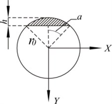
When a transverse open crack occurs on the surface of the th fastening rod, the crack section area and the instantaneous axial force of th rod can be derived respectively as follows:
with .
Substituting the Eq. (8) into the Eq. (9), the instantaneous axial force of the th fastening rod with a crack can be expressed as:
The potential energy of th cracked fastening rod can be given as:
Substituting the Eqs. (1) and (5) into the Eq. (11), the total potential energy of th cracked fastening rod and the others with no crack can be given as:
with:
and the add-on stiffness matrix stiffness matrix as followed in Eq. (13):
It can be found that Eq. (5) and Eq. (12) are different, which shows the cracked rod-fastening rotor system will introduce the add-on stiffness matrix as shown in Eq. (13) besides in Eq. (6) compared with intact rod-fastening rotor system.
It is note that the additional stiffness matrix of the cracked fastening rod as shown in Eq. (13) is asymmetric. This asymmetry will break the existed relatively steady state of rotor system resulting in the change of the system stability. Meanwhile, the contribution of the additional stiffness matrix introduced by the crack is to reduce total stiffness of the system.
2.3. Dynamic equations of cracked rotor bearing system
The finite element method with Timoshenko beam element with four degrees of freedoms at each node is employed to discretize the rotor into 11 elements [24-27]. The four disks, fastening rods and two radial cylindrical bearings are assembled together with the rotor through the finite element method. Then the dynamic equation of the cracked rod-fastening rotor bearing system is formulated as follows:
with:
where , , , and are the mass matrix, gyroscope matrix, stiffness matrix and the external force vector (including gravity and unbalance force), respectively, and the corresponding superscript ‘’, ‘’, and ‘’ stand for the whole system, rotor shaft and disk, respectively. is one single node displacement vector, which have translational and rotational displacement about -and -axes of the fixed coordinate system, i. e. . So for the displacement vector of a rotor with nodes, it can be given as . is the (node number 12) stiffness matrix which consists of . is the stiffness matrix of which the entries of zero entries except at the crack node location are equal to . and are matrix of which the entries of zero entries except at the corresponding node location are equal to and , respectively. The oil force vector can be expressed as , which can be obtained from the typical infinite long bearings assumption [28].
3. Method of solution and nonlinear analysis
3.1. Method of solutions
The whole system have 48 DOFs which contain linear and nonlinear DOFs. Although it is not very high dimension for advanced computer technology nowadays, it also need consume much time for real time simulation at different speeds. To save the computing time and retain necessary DOFs information, the free interface modal synthesis technology [22, 23 29, 30] are employed to reduce the system DOFs. The nonlinear DOFs corresponding to two bearing nodes and four disks nodes and other two corresponding nodes of linear DOFs are retained. Then the reduced system can be given as follows:
where , , , and . is the reduced displacement vector. is a transformation matrix being introduced to reduce the original system. By introducing the state variable , the corresponding reduced system equations in a state space can be written as follows:
By system reduction, the local nonlinearity of nodes which locates in bearings and disks are retained as well as other two linear nodes, which means 32 DOFs in total are kept. Then the nonlinear stability and bifurcation behaviors can be obtained by numerical simulations.
Assuming that the system is subjected to the external periodic load with period , i.e. , which originates from the mass eccentricity. Then periodic solutions can be are calculated by solving a two point boundary value problem, which is defined by Eq. (19) supplemented with the boundary condition . It can be written as:
with , where is a system parameter, which can be the angular speed or the mass eccentricity , etc.
The periodic solutions of the system will become unstable in certain intervals of system parameters. It is important to determine the unstable intervals and which kind of nonlinear dynamic behaviors of system among the periodic, quasi-periodic, and chaotic it is. Here, for a given system parameter, the shooting method [22, 23, 29, 31-33] is adopted to obtain the details of periodic solutions. Then the path-following technique [31, 33] is used to investigate how a periodic solution is influenced by a change of . The whole solution braches of system can be found with this combined technique, which is consist of a predictor-corrector mechanism as shown in Eq. (21) in nature:
For the Eq. (21), the next step solution, i.e. at , can be determined by starting from a known solution at , and combining with the corrected mechanism by using shooting method.
Lastly, the Floquet theory [22, 33] is employed to determine the local stability of periodic motion of nonlinear system. The procedure involves calculating the largest eigenvalues (Floquet multipliers) of the Jacobian matrix (the details see the [22, 23]) produced in the process of the shooting method. In general, the Floquet multipliers must be within the unit circle in the complex plane. While with the change of the system parameter, the stable periodic solution of system will happen to lose stability, which will show different forms of bifurcation.
According to the situation of the maximum Floquet multipliers through the unit circle in the complex plane, the forms of bifurcation can be classified into three modes i.e. period-doubling bifurcation, quasi-periodic bifurcation and “cycle-fol” or “transcritical” bifurcation [23].
Each finite element node of system as shown in Fig. 1 is marked by integer from 1 to 12 in sequence. The corresponding parameters of the cracked and intact rod-fastening rotor bearing system are given in Table 1. The mass eccentricities of four disks are represented by , , , and () which results in the unbalance forces of system. Meanwhile, the numerical results of rod-fastening rotor system model with no crack as referred in [22, 23] are also given for comparison. The simulation results are obtained as shown from Fig. 3-11, respectively, through Fortran program by changing corresponding parameters.
3.2. Simulation results and nonlinear analysis
3.2.1. Effects of crack on the system stability and bifurcation
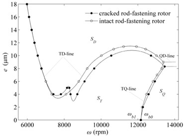
For a given crack depth 0.1 of the cracked fastening rod, the regulations of the stable and unstable solutions of the system with the change of the system parameters and for both cracked rod-fastening rotor bearing system and intact ones are shown in Fig. 3(a).
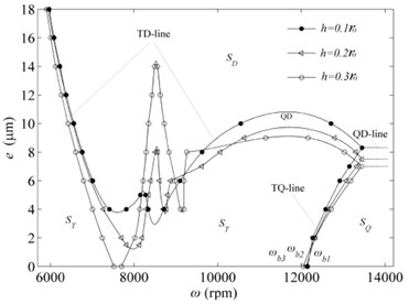
Fig. 3a) e-ω curves of the solution set of stability and bifurcation transition of the cracked and intact rotor systems, b) effects of the crack depth on the system stability and bifurcation
a)
b)
Compared with intact rod-fastening rotor system, in general, the stability and instability regions of the cracked ones also have three parts, the stable periodic motion region , the period-doubling motion region SD and the quasi-periodic motion region which are developed by the corresponding two borderlines of TD-line, TQ-line and QD-line, respectively, as shown in Fig. 3(a). The TD-line and TQ-line are the period-doubling bifurcation borderline and quasi-periodic bifurcation borderline, respectively. Periodic-doubling motion or quasi-periodic bifurcation motion will occur when the rotating speed ω or the mass eccentricities crosses TD-line or TQ-line. The dashed QD-line is the critical parting line of period-doubling bifurcation motion region ST and quasi-periodic bifurcation motion region SQ. The symbols and in Fig. 3(a) as well as and mentioned later in text are linear critical speed of the equilibrium point for the balanced rod-fastening rotor system ( 0) and , , and correspond to the crack depth equaling to 0, 0.1, 0.2, and 0.3, respectively. Hopf bifurcation will occur for the system and subsequently lose stability when the rotating speed exceeds linear critical speed for the balanced rod-fastening rotor system.
It is worth noting that there are some different details between cracked rod-fastening rotor system with a transverse open crack in a fastening rod and intact ones as follows
Firstly, the - curve of cracked rotor system tends to move to the lower right as a whole and the QD-line tends to a downward move. These differences are mainly caused by the existence of crack of the fastening rod which will introduce the additional stiffness and cause system stiffness to reduce. While these changes are very small when the rotating speed is approximately on the left side of the first saddleback of TD-line which corresponds to the location of the first resonance peak in Fig. 4(a) probably. This means the influences of shallow crack of the fastening rod on system dynamic behaviours is small for rod-fastening rotor system when they work under the rotating speeds corresponding to the first resonance peak.
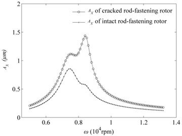
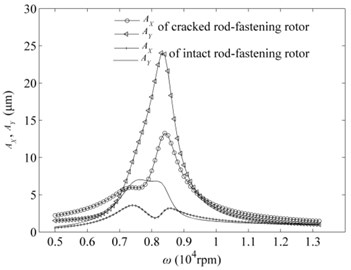
Fig. 4Vibration amplitudes when h= 0.1r0 and e= 1 μm: a) bearing node, b) middle disk node
a)
b)
Secondly, it can be found that it happens to two saddlebacks of TD-line as shown in Fig. 1 which approximately corresponds to the two resonant peaks of bearing node for cracked rod-fastening rotor system as shown in Fig. 4(a). In contrast with the intact rotor system, the TQ-line shows just a saddleback. Thus, they will perform different dynamic behavious and stability in the location of second saddleback of cracked rod-fastening rotor system which one is stable and another is periodic-doubling bifurcation behaviours because of the presence of crack on the surface of the fastening rod. It is also worthwhile to note that the vibration amplitudes of the cracked rod-fastening rotor system under stable region with 1 μm mass eccentricity is bigger compared with the intact rotor system as shown in Fig. 4(a, b), especially for the middle disk node as shown in Fig. 4(b).
Thirdly, the TQ-line shows a linear growth trend with the increment of rotating speeds and the mass eccentricities for two systems. Although the most part of TQ-line seems to move slightly to the right for cracked rotor system, it tends to move slightly to the left when the mass eccentricities equals to zero or near the zero regions. It can be seen that the linear critical speed of cracked rotor system locates on the right of the linear critical speed of intact ones. This shows the cracked rod-fastening rotor system will early to lose stability for balanced ones (mass eccentricities 0) or very small mass eccentricities compared with intact rotor system.
3.2.2. Effects of crack depth on the system stability and bifurcation
From the Fig. 3(b), It can be found the effects of crack depth on the system stability and bifurcation. With the increment of crack depth, the TD-line, QD-line and TQ-line happen to move down except the part between the two saddlebacks which increases. These shows the system stability gradually decreases on the whole due to the reduction of the system stiffness resulting from the crack of the fastening rod. It is note that the influence of crack becomes obvious with the increment of crack depth when the rotating speed locates on the left side of the first downfold of the TD-line, especially for the crack depth greater than 0.2. The rotor system begins to become periodic-doubling motion even the mass eccentricities equal to zero when the crack depth comes up to 0.3. For the balanced rod-fastening rotor system ( 0), the linear critical speed happens to a little shift to left with the increment of crack depth such as on the left of and on the left of . This reveals the stability of the balanced rod-fastening rotor system will decrease with the increment of crack depth which performs some differences on linear critical speed. Besides, it is worth note that the periodic-doubling motion occurring under small or zero mass eccentricities condition is the characteristic signal of cracked rod-fastening rotor system, which always performs stable periodic motion in corresponding region for intact rod-fastening rotor system. These may be useful for detecting the presence of a crack and its depth for this kind of rod-fastening rotor system
3.2.3. Effects of mass eccentricity
In this part, the effects of typical mass eccentricities 0 μm, 8.3 μm, and 12 μm on the dynamic behaviours such as orbits of periodic motion, vibration model, frequency spectrums analysis, and Poincare map are studied as well as the intact ones in literature for comparison.
(1) Mass eccentricity 0 μm.
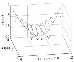
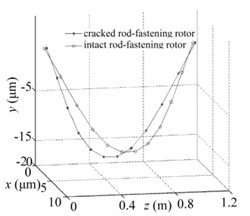
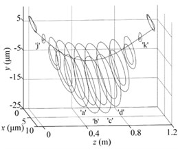
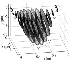
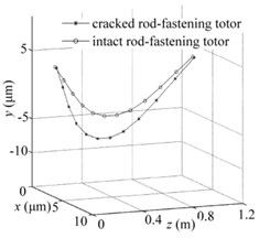
It can be obtained that the cracked rod-fastening rotor system and intact ones lose their stabilities at (12150 rpm) and (12160 rpm), respectively from Fig. 3(a). While the form of transition from steady state to full unstable state is different. After crossing the linear critical speed and , for example at 12240 rpm, the cracked rotor system loses stability by quasi-periodic bifurcation as shown in Fig. 5(a) which shows the orbits of whole 12 nodes and the intact ones by Hopf periodic solution as shown in Fig. 5(b). The vibration modes of rotor shaft of two systems at a transient time is different and it shows the vibration amplitude of cracked rotor system tends to be larger than the intact ones due to the presence of the crack of rod-fastening as depicted in Fig. 5(c).
Fig. 5Periodic solutions for all nodes when e= 0 μm and w= 12240 rpm: a) Quasi-periodic solutions for cracked rod-fastening rotor system with h= 0.1r0, b) Hopf T periodic solutions for intact systems, c) comparison of the whole vibration modes of two systems
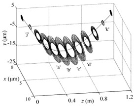
a)
b)
c)
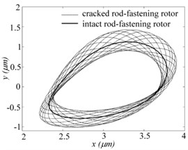
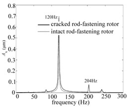
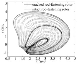
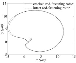
In order to further explore the dynamic behaviours, Fig. 6(a), (b) and (c) shows the orbits and frequency spectrum of bearing node. It can be seen clearly that the quasi-periodic bifurcation behaviours for cracked systems and Hopf periodic bifurcation for intact ones in Fig. 6(a). Besides there are some differences in frequency component, which occurs to whirling frequency about 204 Hz for cracked system except the whirling frequency about 120 Hz compared with the intact ones as shown in Fig. 6(b, c).
(2) Mass eccentricity 8.3 μm.
According to the Fig. 3(a), it can be known that the cracked rod-fastening rotor system occurs to lose stability at 13450 rpm when mass eccentricity 8.3 μm as well as at 13370 rpm for intact ones. Fig. 7(a) shows the periodic-doubling motion at 13458 rpm and periodic-doubling motion at 13440 rpm of bearing node for two systems respectively when 8.3 μm. Poincare maps is a closed curve consisted of limited points for cracked system and the others are two isolated points for intact ones in Fig. 7(b), which confirms the corresponding motions are periodic-doubling and periodic-doubling, respectively. The frequency spectrums of direction are illustrated in Fig. 7(c) which shows the frequency components are very consistent. This means that it is difficult to distinguish the cracked and intact rod-fastening rotor bearing systems by frequency components on this condition.
Fig. 6The bearing node dynamic behaviours when e= 0 μm and w= 12240 rpm for two systems: a) orbits, b) and c) frequency spectrums of X and Y direction, respectively
a)
b)
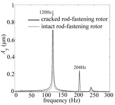
c)
Fig. 7Periodic-doubling (w= 13458 rpm) and quasi-periodic (w= 13440 rpm) solution of bearing nodes for two systems respectively when e= 8.3 μm: a) orbits, b) Poincare map, c) frequency spectrums
a)
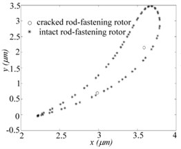
b)
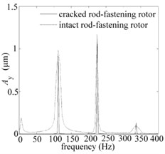
c)
Fig. 8Solutions for all nodes when e= 8.3 μm: a) periodic-doubling solution (w= 13458 rpm) for cracked rod-fastening rotor system, b) quasi-periodic solution (w= 13440 rpm) for intact ones, c) comparison of the whole vibration modes for two systems
a)
b)
c)
Fig. 8(a, b) shows the periodic-doubling motion and quasi-periodic motion of the whole nodes for cracked and intact rod-fastening rotor system, respectively. Fig. 8(c) gives the vibration modes of two systems. Because of the presence of crack for cracked system, the vibration amplitude of cracked system is larger than the intact ones.
(3) Mass eccentricity 12 μm.
The nonlinear dynamic behaviours for two systems are very consistent when the crack depth is 0.1 and the system work on the left side of the first saddleback according to - diagram in Fig. 3(a). It can be seen that the periodic motions of bearing nodes occur for cracked and intact rotor system as shown in Fig. 9(a), and the two isolated points of Poincare maps as shown in Fig. 9(b) also confirm this nonlinear dynamic behaviours. Besides the frequency components of bearing node of frequency spectrums of direction in Fig. 9(c) are also same. In addition, the solutions of whole nodes are very consistent and periodic motions as shown in Fig. 10(a) and (b) as well as the vibration modes in Fig. 10(c). This reveals that the effects of crack are very small to some extent, especially when the system works under in the range of the first resonance peak and has a slight crack depth. While this phenomenon will change with the increment of crack depth as shown in Fig. 3(b).
Fig. 9Periodic-doubling solution (w= 6400 rpm) of bearing nodes for two systems respectively when e= 12 μm: a) orbits, b) Poincare map, c) frequency spectrums of X direction
a)
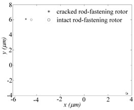
b)
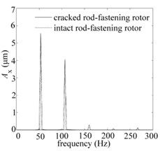
c)
Fig. 10Periodic-doubling solutions for all nodes when e= 12 μm and w= 6400 rpm: a) cracked rod-fastening rotor system, b) intact rotor system, c) the whole vibration modes for two systems

a)
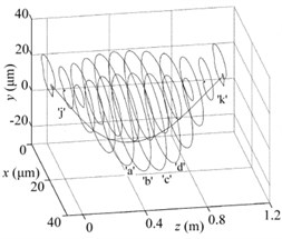
b)
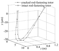
c)
4. Conclusions
A transverse open crack model of a fastening rod is developed, the nonlinear dynamic model of rod-fastening rotor bearing system with crack on the surface of a fastening rod is established based on the finite element method and the stability and bifurcation of system as well as the effects of crack depth and the mass eccentricities on system are investigated. By numerical simulations and nonlinear analysis, some special characteristics of cracked rod-fastening rotor system are founded compared with the intact rod-fastening rotor system in the literature. It also explains the validity of proposed model. The main conclusions are developed as follows:
1) In general, the stability will reduce, and the vibration amplitudes will increase in steady state when there is a crack on the surface of the fastening rod. Because of the presence of crack, this can introduce the add-on stiffness resulting in the reduction of system stiffness and the asymmetric effect. Meanwhile, it will happen to two saddlebacks of periodic-doubling border lines in - diagram which corresponds to the two resonant peaks of bearing node in - diagram. The change of the solution sets of stability and bifurcation transition with the mass eccentricity and rotating speed become complicated when there is a crack compared with the intact system. The influences of the presence of crack on the nonlinear dynamic of system are not obvious when the crack depth is small and the rotating speed is on the left side of the first saddleback of periodic-doubling borderline.
2) With the increment of the crack depth, the reduction of system stiffness and the asymmetric effect become more obvious. This causes the system instability to become more severe and complicated. The borderlines among the stability, periodic-doubling bifurcation, and quasi-periodic bifurcation regions occur to decline except the parts between the first and second saddleback.
For the balanced rod-fastening rotor system ( 0 or near zero), the linear critical speed decreases with the increment of crack depth and the cracked system loses stability by quasi-periodic bifurcation while the intact system by Hopf periodic bifurcation instead. Besides, the periodic-doubling bifurcation easily arises with increment of crack depth when the rotor system works under the balanced or small mass eccentricities states compared with the intact systems in which always represents a stable status.
3) The results of numerical simulation indicate that the effects of crack on the system play a dominant position when the mass eccentricity is zero or small and there exist some differences in orbits, Poincare map, frequency component, and the vibration modes. These provide some useful special characteristics for detecting the presence of crack especially in orbits and frequency components. With the increment of the mass eccentricity and when it exceeds a critical value, the effects of mass eccentricity will play a dominant position and it is not easy to distinguish the two systems just from the routine orbits and frequency components in this state.
References
-
Mayes I. W., Davies W. G. R. The vibrational beaviour of a rotating shaft system containing a transverse crack. IMechE Conference on Vibrations in Rotating Machinery, London, 1976.
-
Nelson H., Nataraj C. The dynamics of rotor system with a cracked shaft. Journal of Vibration Acoustics Stress and Reliability in Design, Vol. 108, Issue 2, 1987, p. 189-196.
-
Gasch R. A. Survey of the dynamic behaviour of a simple rotating shaft with a transverse crack. Journal of Sound and Vibration, Vol. 160, Issue 2, 1993, p. 313-332.
-
Papadopoulos C. A., Dimarogonas A. D. Coupled longitudinal and bending vibrations of a rotating shaft with an open crack. Journal of Sound and Vibration, Vol. 117, Issue 1, 1987, p. 81-93.
-
Chan R. K. C., Lai T. C. Digital simulation of a rotating shaft with a transverse crack. Applied Mathematical Modelling, Vol. 19, Issue 7, 1995, p. 411-420.
-
Sekhar A. S., Dey J. K. Effects of cracks on rotor system instability. Mechanism and Machine Theory, Vol. 35, Issue 12, 2000, p. 1657-1674.
-
Darpe A. K., Gupta K., Chawla A. Experimental investigations of the response of a cracked rotor to periodic axial excitation. Journal of Sound and Vibration, Vol. 260, Issue 2, 2003, p. 265-286.
-
Darpe A. K., Gupta K., Chawla A. Transient response and breathing behaviour of a cracked Jeffcott rotor. Journal of Sound and Vibration, Vol. 272, Issues 1-2, 2004, p. 207-243.
-
Leng X., Meng G., Zhang T., Fang T. X. Bifurcation and chaos response of a cracked rotor with random disturbance. Journal of Sound and Vibration, Vol. 299, Issue 3, 2007, p. 621-632.
-
Sinou J. J. Effects of a crack on the stability of a non-linear rotor system. International Journal of Non-Linear Mechanics, Vol. 42, Issue 7, 2007, p. 959-972.
-
Patel T. H., Darpe A. K. Influence of crack breathing model on nonlinear dynamics of a cracked rotor. Journal of Sound and Vibration, Vol. 311, Issues 3-5, 2008, p. 953-972.
-
Sinou J. J. Experimental study on the nonlinear vibrations and n× amplitudes of a rotor with a transverse crack. Journal of Vibration and Acoustics, Vol. 131, Issue 4, 2009, p. 41008.
-
Gasch R. Dynamic behaviour of the Laval rotor with a transverse crack. Mechanical Systems and Signal Processing, Vol. 22, Issue 4, 2008, p. 790-804.
-
Sawicki J. T., Kulesza Z. Stability of a cracked rotor subjected to parametric excitation. Journal of Engineering for Gas Turbines, Vol. 137, Issue 5, 2014, p. 52508.
-
Davies W. G. R., Mayes I. W. The vibrational behavior of a multi-shaft, multi-bearing system in the presence of a propagating transverse crack. Journal of Vibration Acoustics Stress and Reliability in Design, Vol. 106, Issue 1, 1984, p. 146-153.
-
Ostachowicz M., Krawczuk W. M. Coupled torsional and bending vibrations of a rotor with an open crack. Archive of Applied Mechanics, Vol. 62, Issue 3, 1992, p. 191-201.
-
Al Shudeifat M.-A. Stability analysis and backward whirl investigation of cracked rotors with time-varying stiffness. Journal of Sound Vibration, Vol. 348, 2015, p. 365-380.
-
Butcher E. A. On the modeling of open and breathing cracks of a cracked rotor system. International Design Engineering Technical Conferences and Computers and Information in Engineering Conference, Vol. 5, 2010, p. 919-928.
-
Han Q., Chu F. The effect of transverse crack upon parametric instability of a rotor-bearing system with an asymmetric disk. Communications in Nonlinear Science and Numerical Simulation, Vol. 17, Issue 12, 2012, p. 5189-5200.
-
Nagata N., Inoue T. Finite element analysis of the vibration of a rotor system with an open crack under the harmonic excitation. The Japan Society of Mechanical Engineers part C, Vol. 79, 799, p. 562-572.
-
Murugan B. Finite Element Analysis of Multi-Disk Rotor-Bearing System with Transverse Crack. Ph.D. Thesis, National Institute of Technology, Rourkela, 2015.
-
Liu H., Chen L. Nonlinear dynamic analysis of a flexible rod fastening rotor bearing system. Chinese Journal of Mechanical Engineering, Vol. 46, Issue 19, 2010, p. 53-62.
-
Liu Y., Liu H., Yi J., Jing M. Investigation on the stability and bifurcation of a rod-fastening rotor bearing system. Journal of Vibration and Control, Vol. 21, Issue 14, 2015, p. 2866-2880.
-
Nelson H. D. A finite rotating shaft element using Timoshenko beam theory. Journal of Mechanical Design, Vol. 102, Issue 4, 1980, p. 793-803.
-
Bathe K. J. Finite Element Procedures. Prentice-Hall, New Jersey, USA, 1996.
-
Friswell M. I., Mottershead J. E. Finite Element Model Updating in Structural Dynamics. Springer Dordrecht, 1995.
-
Lalanne M., Ferraris G. Rotordynamics Prediction in Engineering. John Wiley and Sons Ltd., United Kingdom, 1998.
-
Pinkus O., Sternlicit B. Theory of Hydrodynamic Lubrication. McGraw Hill, New York, 1961.
-
Liu H., Liu Y., Song X., Yi J., Jing M. Nonlinear dynamic effect of thrust bearing on a flexible rotor bearing system. ASME Turbo Expo: Turbine Technical Conference and Exposition, 2012.
-
Van De Vorst E. L. B., Fey R. H. B., Kraker A. D. Van Campen DH. Steady-state behaviour of flexible rotor dynamic systems with oil Journal Bearings. Nonlinear Dynamics, Vol. 11, Issue 3, 1996, p. 295-313.
-
Sundararajan P., Noah S. T. Dynamics of forced nonlinear systems using shooting/arc-length continuation method-application to rotor systems. Journal of Vibration and Acoustics, Vol. 119, Issue 1, 1997, p. 9-20.
-
Fey R. H. B., Van Campen D. H., Kraker A. D. Long Term Structural Dynamics of Mechanical Systems with Local Nonlinearities. Journal of Vibration and Acoustics, Vol. 118, Issue 2, 1996, p. 147-153.
-
Ho Y. S., Liu H., Yu L. Effect of thrust magnetic bearing on stability and bifurcation of a flexible rotor active magnetic bearing system. Journal of Vibration and Acoustics, Vol. 125, Issue 3, 2003, p. 307-316.
Cited by
About this article

This research project was supported by the National Natural Science Foundation of China under Grant No. 51475357 and No. 51705399.
