Abstract
In this study, an inverse method for the purpose of identifying the parameters of a single-edge crack in a curved beam is investigated. This method requires both numerical and experimental natural frequencies. The differential quadrature element method (DQEM) is introduced to get the numerical ones. For the purpose of implementing the DQEM the beam is divided into some elements and the governing equations, the continuity and the boundary conditions, are exerted on these elements to create an eigenvalue problem which is solved to obtain the required frequencies. A rotational spring whose stiffness is a function of crack depth is used to model the crack. An objective function with the variables of crack location and depth which is the weighted mean squared error between experimental and numerical frequencies is defined. The artificial bee colony algorithm (ABC) an optimization algorithm inspired by the natural foraging behavior of honeybees is used to minimize the aforementioned objective function and obtain crack parameters. To investigate the accuracy of this non-destructive, fast and easy method, an experimental modal analysis test is conducted on a cracked beam. The results indicate that the position and depth of the crack can be determined successfully using this method. This test is done five times with a different crack depth each time, to show the efficiency of the method for all cracks even small ones. A brief investigation is also done on the effect of crack location and depth on the natural frequencies.
1. Introduction
Curved beams have found widespread applications in different industries, some of which are mechanical devices such as C-clampers, crane hooks, frames of presses, riveting machines, bearings, and many other machine parts; as well as building arches and bridges. However, over time, a variety of reasons may cause deterioration of beams, so in order to prevent probable accidents, repairing and maintenance of them is essential. Cracks are the most common faults observed in different structural parts. Crack formation in one structural part would cause a decrease in the stiffness and strength of the whole structure. Such reduction affects the dynamic parameters of the structure. Therefore, modal parameters can be used to detect the cracks of a structure.
The problem of crack detection in beams has been studied by many researches. Cerri et al. [1] investigated crack detection in a curved beam with hinged supports at both ends. In their study a rotational spring was used to exert the influence of crack. They obtained a relation between the position and stiffness of the spring in terms of natural frequencies. Substituting the experimental natural frequencies in this relation, they obtained the spring stiffness and crack position approximately. Karaagac et al. [2] studied the effects of cracks on a curved beam. They obtained the stiffness matrix and the mass matrix to get natural frequencies, using both the finite element and energy methods. Chen [3] used the DQEM to analyze the in-plane vibration of an arbitrary curved beam applying EDQ. They transformed an equivalent DQ model to produce an EDQ model. Bahador and oyadiji [4] suggested a method for identifying the parameters of both single and multiple cracks in simply supported beams based on the stationary wavelet transform (SWT). Feng et al. [5] studied an approach to determine the damage parameters in structures which can be modeled as beams. They applied the subsection strain energy method (SSEM) on the basis of numerical modal shapes to determine the crack parameters in a beam with an edge crack. They also showed the proposed method application by specifying crack parameters in a blade model. Zhong and Oyadiji [6] investigated specifying the properties of small cracks considering beam-modeled structures. They based the aforementioned approach upon determining how the continuous wavelet transforms (CWTs) corresponding to two sets of modal shape data of a cracked simply-supported beam differ. Mehrjoo et al. [7] introduced a new cracked beam element, with arbitrary position and depth, to develop a new method of identifying damage. In their approach, a sound element was used, however, in order to consider the effect of crack, the stiffness of the element was defined as a function of crack's depth and position. B. Rosales et al. [8] proposed applying a power series technique (PST) and the artificial neural networks (ANNs) for the purpose of specifying damage position and the level of severity. In their study, these two methods were used to specify crack in both a cantilever and a rotating beam. Fernández-Sáez et al. [9] studied a solution to the problem of locating and determining the severity of crack by measuring the first two natural frequencies in a uniform beam simply supported at both ends. The parameters of a crack in L-shaped pipes containing fluid were determined through a study made by Murigendrappa et al. [10]. An inverse method based on calculating natural frequencies was used to determine the location of the crack and the stiffness of the spring which was used to model the crack. The detection of severity and location of cracks was carried out by Homai et al. [11] in a multi-cracked beam by using the mode shapes of the beam before and after being damaged. They used FEM for the purpose of obtaining mode shapes. Yazdanpanah et al. [12] investigated the problem of determining the parameters of a crack in a beam, using a new indicator on the basis of determining mode shapes and their slope and curvature, considering the sound and damaged specimen. Finite element modeling was used to calculate the mode shapes. Moradipour et al. [13] developed a modal strain energy method with the ability to determine the location and severity of crack in complex structures, based on measuring mode shapes of sound and damaged specimen. Xu et al. [14] derived a solution for the problem of damage identification applying chaotic artificial bee colony (CABC) algorithm. They used residuals of natural frequencies and modal assurance criteria (MAC) to form the objective function. He and Zhu [15] extended the problem of damage detection to thin plates on the basis of wavelet finite element model (WFEM). In their study change of modal strain energy was used to localize damage. In addition, the severity of damage was calculated applying a damage quantification equation deduced from differential equations of plate structure motion. Applying FE method to obtain natural frequencies of an Euler-Bernoulli beam with crack of different positions and depths was carried out by Öz and Das [16]. They considered cracked curved beams with different angles.
In this study the problem of crack detection in a curved beam based on an inverse method is investigated. For the purpose of calculating the natural frequencies numerically, the differential quadrature element method for rapidly solving the governing differential equations is presented. The crack is assumed to be always open and is modeled with a rotational spring to exert the effect of it on the stiffness of the beam. In the rest a combination of the DQEM and the artificial bee colony algorithm with an objective function based on the difference between the computed and experimental natural frequencies is introduced as a robust crack detection method. Finally, to demonstrate the effectiveness of the proposed method, the experimental natural frequencies of a sample beam having crack with an increasing depth is obtained to use the aforementioned method to predict the location and depth of the crack.
2. Modeling cracked curved beam
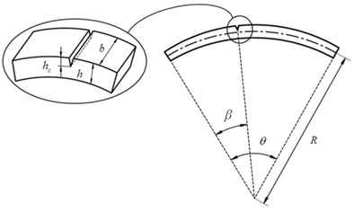
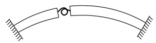
A cracked curved beam, with cross section dimensions, is shown in Fig. 1(a), where is the radius of the beam, is the opening angle of the beam, and are the depth and angular location of the crack, respectively. The crack, which divides the beam into two parts, is modeled as a rotational spring with the stiffness of . (Fig. 1(b))
The equations of motion for the curved beam can be written as [17]:
Note that the effects of shear deformation and rotary inertia as well as the extension of the neutral axis are considered in Eqs. (1-3); thus, the model can be applicable for thick beams with length to thickness ratio less than 10.
Fig. 1a) A cracked curved beam containing dimensions, b) modeling crack utilizing a rotational spring
a)
b)
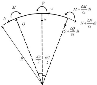
As shown in Fig. 2, which represents an element of a curved beam, , and denote radial and tangential displacements and angle of rotation, respectively. Moreover, , , , , and are the structural properties of the beam, which denote area and moment of inertia of the cross section, mass density per unit volume of the beam material, shear and Young's modulus, and shear factor of the cross section, respectively.
Fig. 2Displacement components and loads of a curved beam
The equations of motion are solved by DQE method (Appendix A).
With the assumption of harmonic excitation at a frequency , applying DQ discretization to the equations of motion at an interior node , in an element , leads to the following discrete equations:
Note that , and denote the mode shapes of radial, tangential displacements and angle of rotation.
Continuity conditions are applied at the interface of two adjacent elements. The continuity conditions defined on the inter-element boundary of two adjacent elements, located in the segments separated by the crack, include radial and tangential displacements, angular rotation, normal and shear forces, and bending moment continuities. In the cross section where crack occurs, however, continuity conditions are the same as mentioned except for the angular rotation.
The radial and tangential displacements and angular rotation continuity conditions at the inter-element boundary of two adjacent elements and + 1 are expressed as:
The discontinuity in the angular rotation at the cross section where crack occurs is expressed as:
whereis the rotational spring stiffness of the beam at the crack location which is a function of crack depth, and it is possible to provide an estimate of it according to the following expression [1]:
where approximately equals to 2, and is the bending moment at the cracked section.
The normal and shear forces, and bending moment continuity conditions at the inter-element boundary of two adjacent elements and can be expressed, respectively, as [17]:
To equate the number of unknowns to that of the equations, three boundary conditions must be considered at each of end points of the beam.
Boundary conditions for a beam clamped at both ends are:
Note that in Eq. (13), the degrees of freedom at the first element start point are set to zero, whereas in Eq. (14), those at the end point of the th element are set to zero. Applying the differential quadrature element method to the equations of motion of the beam, as well as, the continuity and boundary conditions, they are transformed into an algebraic system of eigenvalue problem expressed in the form of Eq. (15):
The indices and denote inner and boundary domains of the elements. Vectors and include the degrees of freedom of inter-element boundary nodes and those of the internal nodes, respectively:
where is the square root of natural frequencies. Solving the resulted eigenvalue problem, the natural frequencies of the cracked curved beam are extracted.
3. Artificial bee colony algorithm
The artificial bee colony algorithm, proposed by Karaboga in 2005 [18], uses the foraging behavior of honey bee swarm for solving optimization problems. In the nature, it is important for a bee colony to increase the amount of nectar supply to the highest level. To achieve this aim, bees attempt to share and organize the responsibilities in an effective way. For the purpose of looking for food, bees are divided into three groups, namely, worker bees, observer bees, and scout bees. Such a food foraging model is also used in the artificial bee colony algorithm. Half the colony acts as worker bees, and the others as observer bees. It is worker bees' duty to utilize the recently-discovered food supplies, and to share information about the quality of the food sources being extracted with other observer bees. Based on such shared data, observer bees, which stay in the hive, choose a food supply to be exploited. The next stage is discovering new food supplies, which is done by the scout bees, searching randomly through the environment. Utilizing the aforementioned behavior of a real bee colony, the function of ABC algorithm can be defined as follows:
1. Initialize the food source positions.
2. Each employed bee produces a new food source in her food source site and exploits the better source.
3. Each onlooker bee selects a source depending on the quality of her solution, produces a new food source in selected food source site and exploits the better source.
4. Determine the source to be abandoned and allocate its employed bee as scout for searching new food sources.
5. Memorize the best food source found so far.
6. Repeat steps (2-5) until the stopping criterion is met.
In first step of the algorithm, ( 1, …, ) solutions are randomly produced in the range of parameters where is the number of the food sources. In the second step of the algorithm, for each employed bee, whose total number equals to the half of the number of food sources, a new source is produced as [18]:
where is a random number uniformly distributed over the [–1 1] interval, index shows the randomly selected food source, and represents the problem dimension. Comparing and , the better one is picked to be exploited by the employed bee. According to step 3, an observer bee is responsible to pick a supply with the probability (Eq. (18)), and generates a new source at the location of the picked source according to Eq. (17). Similar to employed bee, the efficient supply is utilized:
where is the fitness of the solution . After all the sources are divided among onlookers, sources are considered to find out if they must be left. The condition of leaving a source is not being able to get better before the number of cycles exceed a predefined limit. In this case, the related worker bee turns into a scout bee and starts a random search within the realm defined for the problem using Eq. (19):
This procedure continues until the convergence criterion is satisfied (i.e., either completing a definitive number of cycles or acquiring the required accuracy).
In the above algorithm, the goal is to minimize the objective function that is given by:
where is the th experimental natural frequency, and is the th numerical natural frequency of the cracked curved beam obtained using the differential quadrature element method and is the weighting factor related to the th natural frequency which is used to represent the importance of the corresponding natural frequency.
4. experimental modeling
To check the feasibility of the proposed method in terms of crack detection, some experimental tests are performed on a specimen. The properties of the specimen are shown in Table 1. These properties show that the beam is not thick, so the effects of shear deformation and rotary inertia are negligible (Section 2).
Table 1Mechanical specifications of the curved beam
Property | Notation | Value |
Radius of the beam axis | 30.4 (cm) | |
Opening angle of the beam | 119 (deg) | |
Height of the cross section | 1.41 (cm) | |
Base of the cross section | 1.41 (cm) | |
Young’s Modulus | 201.2 (GPa) | |
Poisson’s Ratio | 0.3 | |
Density | 7800 (kg/m3) |
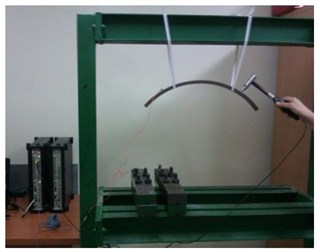
However, in the theoretical model these effects are considered to be applicable to all the beams. The beam is free at both ends. The tests are performed five times by introducing a crack of increasing relative depth of 0.1, 0.2, 0.3, 0.4 and 0.5 at a relative position of 0.252. The relative depth and position are defined as the ratio of crack depth to the cross section height and the ratio of angular position of the crack to the total angle of the beam, respectively. The tests are performed by using the impulsive technique. A hammer (Model AU02, manufactured by Global Test Company) is used to excite the beam. The acquisition of the frequency response function (FRFs) is obtained using a piezoelectric Bruel&Kjaer accelerometer, type 4516, along with a signal analyzer and Pulse LabShop software. The beam is impacted by the hammer at each relative depth, and the first three natural frequencies of it are measured from FRFs data by global FFT method. A typical measured FRF of the system is shown in Fig. 3. Also Fig. 4 shows a general view of the modal test process.
Fig. 3A typical measured FRF of the cracked curved beam
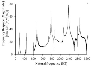
Fig. 4The general modal test arrangement
5. Results
5.1. Experimental natural frequencies precision
Tables 2-4 represent the natural frequencies of the cracked beam specified in Table 1, free at both ends, with crack depths of 0.1, 0.3 and 0.5, using both experimental and differential quadrature element methods. In this study, differential quadrature element method’s results are obtained using 8 nodes in each element and adopting Gauss-Lobatto Chebyshev polynomials.
Table 2The first three natural frequencies of the freely supported cracked beam (crack relative depth: 0.1)
Natural frequency | Value (Hz) | % | |
Experimental | DQEM | ||
First | 162.376 | 162.941 | 0.347 |
Second | 465.752 | 467.676 | 0.413 |
Third | 938.503 | 942.356 | 0.410 |
% = 100 (-)/: error percentage | |||
Table 3The first three natural frequencies of the freely supported cracked beam (crack relative depth: 0.3)
Natural frequency | Value (Hz) | % | |
Experimental | DQEM | ||
First | 161.376 | 161.908 | 0.330 |
Second | 458.002 | 459.616 | 0.352 |
Third | 926.128 | 928.943 | 0.303 |
% = 100 (-)/: error percentage | |||
Table 4The first three natural frequencies of the freely supported cracked beam (crack relative depth: 0.5)
Natural frequency | Value (Hz) | % | |
Experimental | DQEM | ||
First | 157.876 | 158.551 | 0.427 |
Second | 434.752 | 436.152 | 0.322 |
Third | 894.316 | 895.517 | 0.134 |
% = 100 (-)/: error percentage | |||
Note that the experimental results were used as a criterion for measuring error. The tables show the high precision of the experimental natural frequencies, where the percentage of the relative error would not exceed 0.427.
As expected, a progressive decrease in the value of the natural frequencies with respect to the increase in the depth of the crack is observed. Increasing crack depth would decrease beam stiffness (Eq. (9)); thus, the natural frequency which is directly related to stiffness reduces.
For the purpose of investigating the variation of relative natural frequencies by changing mode shapes, the results of Tables (2-4) are classified according to the mode shapes in Fig. 5. Note that relative natural frequency for each mode is defined as the ratio of the natural frequency to the one associated with the crack of depth 0.1.
Fig. 5Variations of the first three natural frequencies of a cracked curved beam due to changing mode shape
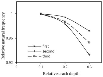
Referring to Fig. 5, the natural frequencies of the first and second mode undergo the least and the most variation by increasing the crack depth. This variation is due to the location of crack. As mentioned discontinuity in rotation angle at the cracked section (Eq. (8)), is the main factor of variation of natural frequencies due to the crack. Since this discontinuity is directly related to bending moment and positions with greater deformation experience greater moments, if the crack occurs at the place of a mode shape node, the natural frequency of that mode is not affected by the crack. On the other hand, the maximum frequency change occurs at the crack position with the greatest deformation.
5.2. Determination of crack location and depth
The relative crack depths and positions detected by the proposed method are tabulated in Table 5. The percentage of location and depth errors were calculated from the following relations:
where and are the predicted and actual relative crack position, and and are the predicted and actual crack depth, respectively.
Note that he solution of ABC method converges after 30 iterations. Moreover, to take into account the stochastic nature of the method, the average results of 10 runs have been considered here.
The results indicate high accuracy of the predicted cracks, where the maximum errors occurred, are limited to 1.1 % for the position of the cracks, and 0.7 % for their depths, respectively. The table also shows that the presented method is capable of predicting small cracks with minimum error (i.e. the first case in the table). Since the beam length is 61.79 cm, the predicted crack locations would be less than 6.8 mm far from the actual crack location. In addition, as the beam thickness is 14.1 mm, the difference between the predicted and the actual values of the depth would not exceed 0.098 mm.
Table 5Crack locations and depths in a curved beam as predicted by the artificial bee colony algorithm
Item | Notation | Value | ||||
Exact crack parameters | 0.252 | |||||
0.1 | 0.2 | 0.3 | 0.4 | 0.5 | ||
Predicted crack parameters | 0.241 | 0.246 | 0.252 | 0.254 | 0.255 | |
0.102 | 0.199 | 0.294 | 0.407 | 0.497 | ||
Error percentage | 1.1 | 0.6 | 0.0 | 0.2 | 0.3 | |
0.2 | 0.1 | 0.6 | 0.7 | 0.3 | ||
6. Conclusions
In this study, the DQEM is implemented to calculate the natural frequencies of a cracked curved beam, numerically. This numerical method is a straightforward one involving no tedious mathematics and can predict fairly accurate natural frequencies of considered both uncracked and cracked beams. Moreover, it can be applicable easily to the curved beams with single or multiple cracks, having various subtended angles, geometry and boundary conditions.
An inverse procedure is also proposed using the artificial bee colony algorithm, as well as the DQEM, for simultaneous detection of crack location and depth. The only input of this algorithm is the first three experimental natural frequencies. To study the proposed procedure, cracks at different depths are created in a beam specimen and the natural frequencies for each case measured to determine the crack parameters. The results revealed that a combination of the differential quadrature element method, and the artificial bee colony, an efficient and rapidly convergent iteration optimization method acts as an efficient and fast method in detecting the crack parameters of the specimen even the cracks of small depth. Moreover, being none destructive is the other advantage of this method which helps to be adopted permanently to prevent probable accidents.
References
-
Cerri M. N., Dilena M., Ruta G. C. Vibration and damage detection in undamaged and cracked circular arches: experimental and analytical results. Journal of Sound and Vibration, Vol. 314, Issue 1, 2008, p. 83-94.
-
Karaagac C., Ozturk H., Sabuncu H. Crack effects on the In-plane static and dynamic stabilities of a curved beam with an edge crack. Journal of Sound and Vibration, Vol. 330, Issue 8, 2011, p. 1718-1736.
-
Chen C. N. DQEM analysis of in-plane vibration of curved beam structures. Advances in Engineering Software, Vol. 36, Issue 6, 2005, p. 412-424.
-
Oyadiji S. O., Bahador A. Single and multiple crack detection in simply supported beams using SWT, Mechanisms and Machine Science, Vol. 23, 2015, p. 265-275.
-
Feng K., Li Z., Gao G., Su X. Y. Damage detection method in complicated beams with varying flexural stiffness. Applied Mathematics and Mechanics (English Edition), Vol. 32, Issue 4, 2011, p. 469-478.
-
Zhong S., Oyadiji S. O. Detection of cracks in simply-supported beams by continuous wavelet transform of reconstructed modal data. Computers and Structures, Vol. 89, Issue 1, 2010, p. 127-148.
-
Mehrjoo M., Khaji N., Ashtiany G. M. New Timoshenko-cracked beam element and crack detection in beam-like structures using genetic algorithm. Inverse Problems in Science and Engineering, Vol. 22, Issue 3, 2014, p. 359-382.
-
Rosales B. M., Filipich P. C., Buezas S. F. Crack detection in beam-like structures. Engineering Structures, Vol. 31, Issue 10, 2009, p. 2257-2264.
-
Fernández Sáez J., Morassi A., Pressacco M., Rubio L. Unique determination of a single crack in a uniform simply supported beam in bending vibration. Journal of sound and vibration, Vol. 371, Issue 9, 2016, p. 94-109.
-
Murigendrappa S. M., Maiti S. K., Srirangarajan H. R. Detection of crack in L-shaped pipes filled with fluid based on transverse natural frequencies. Structural Engineering and Mechanics, Vol. 21, Issue 6, 2005, p. 635-658.
-
Homai F., Shojaee S., Amiri G. G. A direct damage detection method using multiple damage localization index based on mode shapes criterion. Structural Engineering and Mechanics, Vol. 49, Issue 2, 2014, p. 183-202.
-
Yazdanpanah O., Seyedpoor S. M., Bengar A. H. A new damage detection indicator for beams based on mode shape data. Structural Engineering and Mechanics, Vol. 53, Issue 4, 2015, p. 725-744.
-
Moradipour P., Chan T., Gallage C. An improved modal strain energy method for structural damage detection, 2D simulation. Structural Engineering and Mechanics, Vol. 54, Issue 1, 2015, p. 105-119.
-
Xu H. J., Ding Z. H., Lu Z. R., Liu J. K. Structural damage detection based on Chaotic Artificial Bee Colony algorithm. Structural Engineering and Mechanics, Vol. 55, Issue 6, 2015, p. 1223-1239.
-
He W. Y., Zhu S. Adaptive-scale damage detection strategy for plate structures based on wavelet finite element model. Structural Engineering and Mechanics, Vol. 54, Issue 2, 2015, p. 239-256.
-
Öz H. R., Das M. T. In plane vibrations of circular curved beams with a transverse open crack. Mathematical and Computational Applications, Vol. 11, Issue 1, 2006, p. 1-10.
-
Issa M. S., Wang T. M., Hsiao B. T. Extensional vibration of continuous circular curved beams with rotary inertia and shear deformation. Journal of Sound and Vibration, Vol. 114, Issue 2, 1987, p. 297-308.
-
Karaboga D., Basturk B. On the performance of artificial bee colony (ABC) algorithm. Applied Soft Computing, Vol. 8, Issue 1, 2008, p. 687-697.
Cited by
About this article

