Abstract
Combining P-type iterative learning (IL) control, fuzzy logic control and artificial bee colony (ABC) algorithm, a new optimal fuzzy IL controller is designed for active vibration control of piezoelectric smart structures. In order to accelerate the learning speed of feedback gain, the fuzzy logic controller is integrated into the ANSYS finite element (FE) models by using APDL (ANSYS Parameter Design Language) approach to adjust adaptively the learning gain of P-type IL control. For improving the performance and robustness of the fuzzy logic controller as well as diminishing human intervention in the operation process, ABC algorithm is used to automatically identify the optimal configurations for values in fuzzy query table, fuzzification parameters and defuzzification parameters, and the main program of ABC algorithm is operated in MATLAB. The active vibration equations are driven from the FE equations for the dynamic response of a linear elastic piezoelectric smart structure. Considering the vibrations generated by various external disturbances, the optimal fuzzy IL controller is numerically investigated for a clamped piezoelectric smart plate. Results demonstrate that the proposed control approach makes the feedback gain has a fast learning speed and performs excellent in vibration suppression. This is demonstrated in the results by comparing the new control approach with the P-type IL control.
1. Introduction
As an intelligent control strategy, iterative learning (IL) control has a simple controller structure and doesn’t require accurate system model. According to fully utilizing the past control experience, it can improve the current control performance of the system by operating repetitively over a fixed time interval [1]. In 1978, IL control was first proposed by Uchiyama in Japanese [2], which did not get much attention. After one critical report published by Arimoto in English [3], IL control had a significant progress in both theory and application [4, 5]. In many cases, it is essential to apply this algorithm to find the system inputs that make the system outputs close possible to the desired outputs, such as hysteresis compensation in a piezoelectric actuator [6], achievement of the extreme precision motion tracking for the control system [7], state estimation on repetitive process systems [5], point-to-point motion control of robotic arm [8]. However, few papers can be found about the applications of IL control for active vibration control of piezoelectric smart structures. Zhu et al. [9] and Tavakolpour et al. [10] firstly applied P-type IL control to vibration attenuation of piezoelectric smart structures, and the efficiency of P-type IL controller had been proven in their studies. In addition, Fadil et al. [11] combined P-type IL control and PID control to design a new intelligent PID controller for vibration suppression of the piezoelectric smart cantilever beam, in which the P-type IL control is applied to tune the parameters of the PID controller.
In the studies above, although P-type IL controllers can effectively attenuate the structural vibrations at some excitation frequencies, the performances of controllers for vibration suppression are still not obvious when the piezoelectric smart structure is excited by its first natural frequency. Besides, control effectiveness of actuators is effective at the locations of sensors, and they are not able to compensate the unwanted vibrations effectively at other locations [12]. In P-type IL control, thousands of iterations are needed for achieving the satisfying control precision, which leads to learning speed of feedback gain slow [10, 13]. Moreover, unreasonable selections of learning gains may directly cause control spillover or even system instability, which makes the reduction of system robustness [14].
Due to the ability to deal with nonlinearities, uncertainties and imprecision, fuzzy logic has been successfully employed by several research groups for different controller design [15-17]. Without exact mathematical model of the structure and certain loading conditions, fuzzy logic controller can be designed in a quite simple way. In order to speed up the learning speed of feedback gain, the learning gain of P-type IL control is set up by fuzzy logic controller in this paper. However, the effectiveness of fuzzy logic controller depends substantially on appropriate configurations of the membership functions, selections of fuzzy rules and proper operations of the fuzzification and defuzzification, which are all based on the knowledge and experience of researchers and problems being considered [18]. Different optimization technique such as genetic algorithm (GA) [19], ant colony optimization (ACO) [20], and particle swarm optimization (PSO) [21-23] have widely been used to find optimum controller parameters for improving the performance of dynamic systems. Another notable optimization algorithm currently being employed is the artificial bee colony, and the main reason of using this algorithm is due to its triple search capability which forages the local and global search space for the optimum solution. The comparative investigations of ABC optimization technique are carried out against GA, ACO and PSO, ABC searching is able to find a better optimum solution [24], the similar performance is exhibited by the PSO technique as well [24-26]. However, ABC algorithm possesses a higher speed in comparison with PSO [25, 26]. For improving the performance of the fuzzy logic controller, enhancing the robustness of the controller and diminishing human intervention in the operation process, some control approaches were proposed by combining fuzzy logic control and artificial bee colony (ABC) algorithm [27-29]. In these studies, the ABC searching is used to simultaneously auto-tune the parameters of membership functions and fuzzy rules. However, few studies report that ABC algorithm is applied to optimize fuzzification parameters and defuzzification parameters.
Vibration control of structures such as plates and shells always bring a challenge in aerospace fields because of the complexity and density of the vibration modes. The strategy that discrete piezoelectric actuator-sensor pairs are glued on both surfaces of the plate realizes low weight and effective control for structural vibration [30]. The plate integrated piezoelectric actuator-sensor pairs thus becomes a multi-input-multi-output (MIMO) system. If an actuator fails to perform as expected, the performance of its neighboring actuators will be affected negatively. In this system, the mutual effect among all actuators exists in the whole process of active vibration control, and this kind of mutual effect is always uncertain information. The uncertainty caused by mutual effect brings a great challenge to choose the safe ranges of all the input and output variables, so that the values of fuzzification parameters and defuzzification parameters are difficult to be selected. In this paper, the optimal configurations of the fuzzy logic controller for fuzzification parameters and defuzzification parameters are found based on ABC algorithm. In order to avoid complicated fuzzy inference process and reduce time consumption, a fuzzy query table is established. The values of fuzzy output variable can be chosen directly from the fuzzy query table in the process of active vibration control, and the optimal values in the fuzzy query table are also searched by ABC algorithm. It is the way in which all actuators can affect each other positively so that the optimum control effectiveness can be achieved.
To design a system of piezoelectric smart structure for active vibration control, both control strategy and model of smart structures integrated piezoelectric materials are necessary to be considered. The finite element (FE) method is a widely accepted and powerful tool to deal with the piezoelectric smart structures. Some kinds of efficient and accurate electro-mechanically coupled dynamic FEs of smart structures have already been developed [31-33]. Among commercial FE analysis codes, ANSYS has the ability to model smart structures with piezoelectric materials, and H Karagülle et al. [34] successfully integrated the vibration control actions into the ANSYS modeling, and the solution is achieved as well.
By fusing P-type IL control, fuzzy logic control and ABC algorithm, a new optimal fuzzy IL control approach is developed for vibration control of piezoelectric smart structures in this paper. For accelerating the learning speed of feedback gain, the learning gain can be adjusted adaptively by fuzzy logic controller. In order to improve the performance and robustness of the fuzzy logic controller, the ABC searching is used to find the optimal parameters of the fuzzy logic controller. The P-type IL controller and the fuzzy logic controller included the fuzzy query table are integrated into the ANSYS FE model by using ANSYS Parameter Design Language (APDL) approach, and ABC algorithm is realized in MATLAB. The control strategy is numerically investigated for a clamped piezoelectric smart plate under various external disturbances, and the results are illustrated and extensively discussed at the end.
The rest of this paper is organized as follows. In Section 2, based on the FE model of a piezoelectric smart structure, a state space model of the linear system is developed for control law design. The P-type IL control is described for using vibration control of piezoelectric smart structures. Section 3 introduces the designing of the optimal fuzzy IL control in detail. In Section 4, numerical simulations are presented to demonstrate the usefulness and advantages of the proposed control approach. The last section concludes the paper.
2. Modeling and P-type IL control
2.1. Dynamic finite element model
The linear electro-mechanically coupled dynamic FE equation of smart structures can be written as [35]:
where, and represent the structural displacement vector and the electric potential vector; , , , () and are the structural mass matrix, the damping matrix, the structural stiffness matrix, the piezoelectric coupling matrix, the dielectric stiffness matrix, respectively; and are the structural load vector and the electric load vector, respectively.
The damping matrix is usually defined as a linear combination of the structural mass matrix and the structural stiffness matrix as follows:
where, the constants and are the Rayleigh’s damping coefficients.
2.2. P-type IL control
As a type of IL control, the P-type IL control algorithm learns the tracking error from the previous iteration and uses an update rule to adjust the control signal in the current iteration to reduce the tracking error [36]. Fig. 1 demonstrates the block diagram of P-type IL control. and are input signal and measured output signal at the th iteration, respectively, and both of them are stored in memory when the system operates. The P-type IL control evaluates the current performance of dynamic system based on the output error , where is the desired output signal.
Fig. 1Block diagram of P-type IL control algorithm
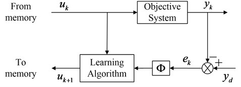
The update rule of the P-type IL control can be expressed as [37]:
where, is the learning gain. An iterative method computes successive approximations such that the output of the system approaches an appropriate value as time increase. However, the learning process should be accomplished within a limited period, over learning may lead to control spillover or system instability once it enters a ‘dangerous zone’ [10]. Therefore, the number of iterations should be limited to the predefined value so that the system knows when to stop the learning process.
2.3. Control mechanism
The piezoelectric sensor generates output electric potential when the structure is oscillating. The partitioned global piezoelectric FE equations of (1) can be easily uncoupled into the following independent equations for the sensor output electric potential:
and the structural displacement:
where, .
Note that is usually zero in sensor. Thus, the sensor output electric potential can be rewritten as:
In the application of vibration suppression, the desired output signal is always defined as zero. Considering the sensor output electric potential as feedback signal, the output error at time instant is defined as:
The output error change at time instant can be defined as:
According to the update rule of P-type IL control in Eq. (3), the feedback gain at time instant can be given as:
The electric potential is amplified and fed back into the actuator. The input voltage to the actuator is expressed as:
where, is the feedback gain in Eq. (9), is the sensor output electric potential in Eq. (6).
The electric load vector can be defined as:
where, is electric load feedback control coefficient.
The feedback control force is defined as [30], combining with the Eqs. (6), (10) and (11), can be rewritten as:
The feedback control force generated by actuator is used to suppress the vibration of piezoelectric smart structure. Substituting Eqs. (6), (10), (11) into Eq. (5), the active vibration control equations of piezoelectric smart structure can be expressed as:
3. Optimal fuzzy IL control design
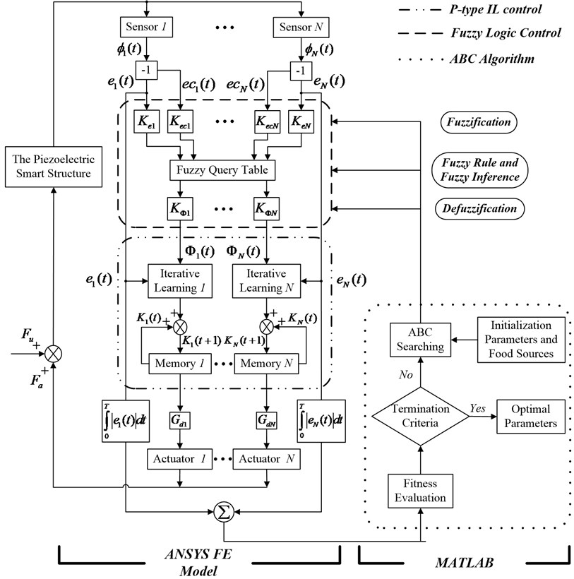
The optimal fuzzy IL control system for vibration suppression of piezoelectric smart structures can be designed by applying MATLAB and ANSYS. For a piezoelectric smart structure with piezoelectric actuator-sensor pairs, the optimal fuzzy IL control system is shown in Fig. 2, and each actuator-sensor pair is controlled independently. The P-type IL control, the fuzzy logic control and the ABC algorithm has been circled by different line types, respectively. By using APDL approach, P-type IL controller and fuzzy logic controller is incorporated into the ANSYS FE model to simulate the vibration control actions of the piezoelectric smart structure. The main program of ABC algorithm is operated in MATLAB.
In Fig. 2, the whole implementation of optimal fuzzy IL controller is presented clearly. In ANSYS FE model, the Sensor generates output electric potential in Eq. (6), when the piezoelectric smart structure is forced by external disturbance . The output error of the Sensor in Eq. (7) and output error change of the Sensor in Eq. (8) act as input variables in fuzzy logic control, and the output variable is the learning gain in Eq. (9). and denote the fuzzification parameters that convert the practical input values into linguistic levels, is the defuzzification parameter which transforms the values of fuzzy output variables into practical output values. In this paper, it is assumed that the values of all fuzzy output variables are chosen from the unique fuzzy query table. For accelerating the learning speed of feedback gain in Eq. (9), the learning gain can be adjusted adaptively by fuzzy logic controller. is electric load feedback control coefficient, where, , is the number of actuator-sensor pairs. The feedback control force in Eq. (12) generated by actuators is used to suppress the vibration of piezoelectric smart structure.
In MATLAB environment, the initial values of optimized parameters (including fuzzification parameters, defuzzification parameters and values in fuzzy query table) are generated randomly by using ABC algorithm, and these initial values are then delivered to the ANSYS FE model to update the current data. The vibration control actions of the piezoelectric smart structure begin to be simulated in ANSYS. As long as the training period has been reached, the value of objective function is saved and transmitted to the program in MATLAB to operate the fitness evaluation. The objective function of optimization problem is formulated based on the minimization in the sum of integral absolute output error of all sensors:
where, is the training period. The choice of training period should guarantee that control system instability will not happen after this specified time. The new set of optimized parameters will be memorized if its fitness value is better than that of the current one; otherwise, the current solution set is retained. This search process is repeated until the termination criterion is satisfied. Finally, the optimal configuration of the parameters for optimal fuzzy IL controller can be obtained. The detailed process of the fuzzy logic control and ABC algorithm has been designed as follow.
Fig. 2The block diagram of optimal fuzzy IL control
3.1. Fuzzy logic control
The fuzzy logic controller designed in this paper involves three basic steps [38, 39]: fuzzification, fuzzy rule and fuzzy inference, defuzzification.
3.1.1. Fuzzification
All of input and output variables should be decided in this step and the fuzzy sets are constructed over all input and output variables. The sensor output electric potential acts as feedback signal, this paper considers the output error in Eq. (7) and its change in Eq. (8) as input variables, and the output variable is the learning gain in Eq. (9). These input and output variables in the fuzzy set are represented by , and , respectively. The ranges of practical output error and output error change can be defined as and . And the corresponding domain of 23.3 GPa and 23 GPa are defined as and , respectively, then:
where, and are fuzzification parameters, , ; and are the maximum output error value and maximum output error change value.
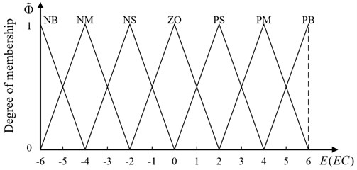
A triangular-type membership function, as shown in Fig. 3, is employed to convert all input and output variables into linguistic variables. In this paper, membership functions of , and are defined in the same way. The values of membership functions are set in the range [0, 1]. There are seven different linguistic terms corresponding to linguistic variables, namely, NB (negative big), NM (negative middle), NS (negative small), ZE (zero), PS (positive small), PM (positive middle) and PB (positive big), respectively.
Fig. 3Membership functions for Φ3= 0.0078, Φ4= 0.0148 and Φ~
3.1.2. Fuzzy rule and fuzzy inference
The fuzzy rule is a significant factor that influences the performance of fuzzy logic controller in a large degree. Mamdani inference method is employed to generate the fuzzy rules in this paper, and the th fuzzy rule can be defined as:
where, 0.0078 and 0.0148 represent the input fuzzy variables, is the output fuzzy variable; and represent the linguistic values of the input fuzzy variables, is the linguistic value of the output fuzzy variable. The 49 fuzzy rules are established for adjustment of learning gain, and listed in Table 1.
Table 1Fuzzy rules
EC | E | ||||||
NB | NM | NS | ZO | PS | PM | PB | |
NB | NB | NB | NM | NS | NS | ZO | ZO |
NM | NB | NB | NM | NS | ZO | ZO | ZO |
NS | NM | NM | NS | NS | ZO | ZO | PS |
ZO | NS | NS | NS | ZO | PS | PS | PS |
PS | NS | ZO | ZO | PS | PS | PM | PM |
PM | ZO | ZO | ZO | PS | PM | PB | PB |
PB | ZO | ZO | PS | PS | PM | PB | PB |
The complicated fuzzy inference process inevitably causes time-delay, which may result in the degradation of control efficiency or even instability of control system [40]. An alternative approach to reduce time consumption in fuzzy inference is that establishing a fuzzy query table. It is given in Table 2. In the process of vibration control, the values of fuzzy output variables are chosen from the fuzzy query table directly, which can improve the real-time control performance of the system.
Table 2The fuzzy query table
EC | E | ||||||||||||
–6 | –5 | –4 | –3 | –2 | –1 | 0 | 1 | 2 | 3 | 4 | 5 | 6 | |
–6 | –5 | –5 | –5 | –4 | –4 | –4 | –4 | –3 | –2 | –1 | 0 | 0 | 0 |
–5 | –5 | –4 | –4 | –4 | –4 | –3 | –3 | –3 | –2 | –1 | 0 | 0 | 0 |
–4 | –5 | –4 | –4 | –4 | –4 | –3 | –2 | –2 | –2 | –1 | 0 | 0 | 0 |
–3 | –4 | –4 | –4 | –3 | –3 | –3 | –2 | –1 | –1 | 0 | 1 | 1 | 1 |
–2 | –4 | –4 | –4 | –3 | –2 | –2 | –2 | –1 | 0 | 1 | 2 | 2 | 2 |
–1 | –4 | –3 | –3 | –3 | –2 | –1 | –1 | 0 | 1 | 1 | 2 | 3 | 3 |
0 | –4 | –3 | –2 | –2 | –2 | –1 | 0 | 1 | 2 | 2 | 2 | 3 | 4 |
1 | –3 | –3 | –2 | –1 | –1 | 0 | 1 | 1 | 2 | 3 | 3 | 3 | 4 |
2 | –2 | –2 | –2 | –1 | 0 | 1 | 2 | 2 | 2 | 3 | 4 | 4 | 4 |
3 | –1 | –1 | –1 | 0 | 1 | 1 | 2 | 3 | 3 | 3 | 4 | 4 | 4 |
4 | 0 | 0 | 0 | 1 | 2 | 2 | 2 | 3 | 4 | 4 | 4 | 4 | 5 |
5 | 0 | 0 | 0 | 1 | 2 | 3 | 3 | 3 | 4 | 4 | 4 | 4 | 5 |
6 | 0 | 0 | 0 | 1 | 2 | 3 | 4 | 4 | 4 | 4 | 5 | 5 | 5 |
3.1.3. Defuzzification
Practical output values are essential for control system to obtain the appropriate control outputs. The range of the practical output value can be defined as , and the corresponding fuzzy value is , and its domain is , then:
where, is defuzzification parameter, ; 1, 2, …, 13 is the maximum practical output value.
Then, a time-varying P-type version of the IL control update rule given in Eq. (9) can be rewritten as:
The learning gain in Eq. (19) can be tuned adaptively by the fuzzy logic controller.
3.2. ABC algorithm
In Fig. 2, there are fuzzification parameters and defuzzification parameters that will be optimized in closed-loop control system. In addition, the values of fuzzy query table in Table 2 should also be optimized. The fuzzy query table is parameterized and represented in Table 3 that has 169 tuning parameters. Therefore, the total optimized parameters for the optimal fuzzy IL controller are 3 + 169. In this paper, the optimization problem is to find the parameters , , and so that the objective function, given by Eq. (14), is minimized, where , and . Constraints of this optimization problem are:
Subject to:
if 14, then 0,
if the corresponding value of in Table 2 is –5, then ,
if the corresponding value of in Table 2 is –4, then ,
if the corresponding value of in Table 2 is –3, then ,
if the corresponding value of in Table 2 is –2, then ,
if the corresponding value of in Table 2 is –1, then ,
if the corresponding value of in Table 2 is 0, then ,
if the corresponding value of in Table 2 is 1, then ,
if the corresponding value of in Table 2 is 2, then ,
if the corresponding value of in Table 2 is 3, then ,
if the corresponding value of in Table 2 is 4, then ,
if the corresponding value of in Table 2 is 5, then , where:
Table 3The parameterized version of fuzzy query table
EC | E | ||||||||||||
–6 | –5 | –4 | –3 | –2 | –1 | 0 | 1 | 2 | 3 | 4 | 5 | 6 | |
–6 | |||||||||||||
–5 | |||||||||||||
–4 | |||||||||||||
–3 | |||||||||||||
–2 | |||||||||||||
–1 | |||||||||||||
0 | |||||||||||||
1 | |||||||||||||
2 | |||||||||||||
3 | |||||||||||||
4 | |||||||||||||
5 | |||||||||||||
6 | |||||||||||||
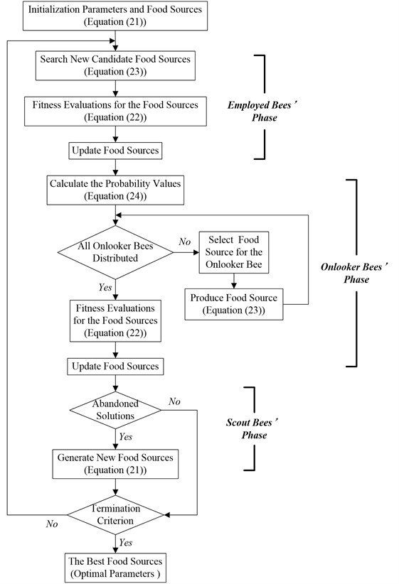
As a global optimization algorithm, the ABC algorithm is widely used to solve multidimensional optimization problems [27]. Three types of honeybees, namely, employed bees, onlooker bees and scout bees, incorporate to search the best food sources by foraging behavior of a bee colony. Each type of a bee colony is a phase in ABC algorithm.
3.2.1. Initialization parameters and food sources
ABC algorithm commences the search process by generating randomly food sources. In other words, the initial values of fuzzification parameters, defuzzification parameters and the fuzzy query table are randomly generated in this subsection. A food source represents a possible optimization problem solution, and the th dimension variable of the th food source is given as:
where, is the number of food sources or employed bees, denotes the dimensionality of the optimization problem; and are the upper and lower bounds of the th dimension variable, respectively.
3.2.2. Fitness evaluation
After producing food sources, the objective function specific for the optimization problem is operated. All the fitness values of the food sources can be calculated by fitness function, the fitness function of the th food source is given as:
where, is the value of objective function.
3.2.3. ABC searching
In ABC algorithm, employed bees’ phase, onlooker bees’ phase and scout bees’ phase are used to search for the optimal parameters. The greedy selection is applied to select the tuning parameters that provide the smallest value of fitness function as the optimal parameters.
Employed bees’ phase: In the neighborhood of the current food sources, each employed bee tries to search a new candidate food source. The candidate solution can be generated from the old solution , shown as follow:
where, and are random indexes, is different from ; is randomly produced in the range [–1, 1]. The fitness values of the candidate food sources are calculated based on Eq. (22). By greedy selection, the new food source will be memorized if its fitness value is better than that of the current one; otherwise, the current source is retained.
Onlooker bees’ phase: As long as all employed bees complete the search process, the information about the food sources is communicated to the onlooker bees. Onlooker bees choose more profitable food sources based on the probability value, and probability can be calculated as follow:
where, is the probability of th food source selected by an onlooker bee. After the selection, the onlooker bee tries to improve the solution of employed bee. It randomly determines a neighborhood food source by using Eq. (23), and its fitness value is computed. The greedy selection is applied to remove or retain the old food source.
Scout bees’ phase: If the employed or onlooker bees show no further improvement over a continuous pre-determine number which is called “limit”, this solution is assumed to be exhausted and need to be abandoned. Then, the employed bees become the scout bees. The new food sources will be discovered by the scout bees based on Eq. (21).
3.2.4. Termination criterion
The search process conducted through the phases of ABC algorithm is repeated until a predetermined termination criterion is satisfied. In this paper, the termination criterion of ABC algorithm is the maximum number of cycles.
3.2.5. Optimal parameters
When the termination criterion is fulfilled, the optimal set of tuning parameters has been obtained in the search space.
Fig. 4 shows the steps in the parameters optimization of the fuzzy logic controller using ABC algorithm.
Fig. 4The flowchart of ABC algorithm
4. Numerical simulations
In this section, the example for vibration control simulations of smart structures is a piezoelectric smart plate with all clamped edges. The piezoelectric smart plate consists of one aluminum plate (305 mm×305 mm×0.8 mm), on which ten PZT-5H piezoelectric patches (30.5 mm×30.5 mm×1 mm) with opposite polarizations pointing outward are bonded in pairs on both sides of the plate, as shown in Fig. 5. The upper piezoelectric patches work as actuators to control the structural vibration, while the lower ones work as sensors to obtain the vibration information. As can be seen in Fig. 5, five piezoelectric actuator-sensor pairs are marked with , , , , and , respectively. The localization of the actuator-sensor pairs are made by reference to [41]. The material properties of aluminum plate and PZT-5H piezoelectric patches are listed in Table 4.
Fig. 5The smart plate with piezoelectric patches
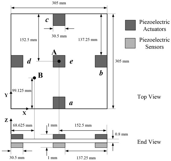
Table 4Material properties of aluminum and PZT-5H
Parameters | Al [30] | PZT-5H [34] |
Density (kg/m3) | 2800 | 7500 |
Young’s modulus (GPa) | 68 | – |
Poisson’s ratio | 0.32 | – |
Elastic stiffness (GPa) | – | 126 |
– | – | 79.5 |
– | – | 84.1 |
– | – | 117 |
– | – | 23.3 |
– | – | 23 |
Piezoelectric strain (C/m2) | – | 12.6 |
– | – | –6.5 |
– | – | 23.3 |
Permittivity (F/m) | – | 1.503×10⁻⁸ |
– | – | 1. 3×10⁻⁸ |
In order to validate the present dynamic FE model established by ANSYS, the first six natural frequencies of the aluminum plate are calculated (in Table 5), and the results imply good agreement by comparing to the theoretical results [42] and numerical results [30].
Table 5The first six natural frequencies of the aluminum plate
Mode | Theoretical results (Hz) [42] | Numerical results (Hz) [30] | Present results (Hz) |
1 | 73.959 | 73.9 | 73.98 |
2 | 150.85 | 150.8 | 150.96 |
3 | 222.41 | 222.4 | 222.67 |
4 | 270.54 | 270.6 | 270.83 |
5 | 271.65 | 271.9 | 272.11 |
6 | 339.08 | 339.3 | 339.71 |
In this paper, the 3-D solid element (SOLID45) is used for simulating the aluminum plate, and the 3-D solid element (SOLID5) is applied for simulating piezoelectric patches. The aluminum plate and each piezoelectric patch are meshed with 40×40×1 elements and 4×4×1 elements, respectively. The degrees of electric freedom for the nodes at top and bottom surfaces of piezoelectric patches are coupled by the ANSYS command CP. The electrical boundary condition of piezoelectric patch is set to be short-circuited on the surface that is bonded with aluminum plate. Modal analysis is performed to determine the time step [26]. The first five natural frequencies of the piezoelectric smart plate are given in Table 6. The time step can be taken as 1/(60), where is the first natural frequency. The Rayleigh’s damping coefficients ( 0.005 %) are defined. The initial value of in Eq. (9) is assumed to be zero. The pre-defined parameters of the ABC algorithm are given in Table 7.
ABC algorithm can initialize the ranges of the research on the worst cases that will allow controlling the system in some critical situations. This advantage depends on its ability to close to the optimal parameters while maintaining a good compromise between the desired performance and the various critical situations, so it can adapt to the change of the system parameters. Considering the objective function of optimization problem in Eq. (14), ABC algorithm understands the behavior of the system and then at each iteration the honeybees enhance their performances to find the best controller parameters.
Table 6The first five natural frequencies of the piezoelectric smart plate
Mode | Natural frequency (Hz) |
1 | 89.122 |
2 | 193.50 |
3 | 265.01 |
4 | 294.19 |
5 | 374.81 |
Table 7ABC parameter setting
Parameter | Value |
Colony size | 400 |
Food sources | 200 |
Maximum number of cycles | 50 |
Limit | 300 |
Considering the vibrations generated by various external disturbances, including impact excitation, harmonic excitation and random excitation, different simulations are investigated to understand the control effectiveness of optimal fuzzy IL control approach. In this paper, note that the trained parameters obtained by short training period (0.0241 s, 0.0227 s, 0.0220 s, respectively) are applied to the long-term optimizations (0.30 s, 0.35 s, 0.44 s, respectively). The long-term optimizations can not only provide better solutions but also consume longer time on calculation. The short-term data is preferable as long as the data of short-term and long-term are almost the same [43]. For the parameters of P-type IL controller in these simulations, the number of iterations is limited to 1100 as the stopping criterion, and the values of fixed learning gains are chosen as 0.0082, 0.0074, and 0.0148 for different simulations. In order to evaluate the optimal fuzzy IL control approach, the displacement responses of the piezoelectric smart plate are given at Point A and B on the piezoelectric smart plate, and their positions are shown in Fig. 5.
4.1. Impulsive excitation
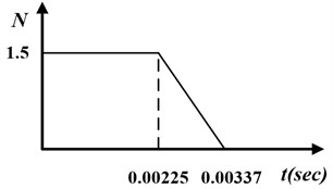
In the first simulation, the piezoelectric smart plate is excited by an impulsive force (shown as Fig. 6) at the Point A.
Fig. 6The impulsive excitation
The best configurations of fuzzification parameters, defuzzification parameters and values in fuzzy query table are shown in Table 8 and Table 9, respectively. Comparing the values of fuzzy query table in Table 2, some areas that values changed notable are surrounded by dotted lines in Table 9.
Table 8The optimal values of the fuzzification parameters and defuzzification parameters
Actuator | Case 1 | Case 2 | Case 3 | ||||||
a | 0.3296 | 2.2334 | 0.0468 | 1.5615 | 4.7199 | 0.2565 | 0.9109 | 3.4465 | 0.1395 |
b | |||||||||
c | |||||||||
d | |||||||||
e | 0.8790 | 7.5713 | 0.0010 | 1.3250 | 2.5109 | 0.0489 | 1.2091 | 2.2723 | 0.0011 |
Table 9The optimal fuzzy query table for impulsive excitation
EC | E | ||||||||||||
–6 | –5 | –4 | –3 | –2 | –1 | 0 | 1 | 2 | 3 | 4 | 5 | 6 | |
–6 | –5.0 | –4.9 | –4.9 | –4.4 | –4.4 | –3.8 | –3.6 | –3.3 | –2.2 | –1.9 | –1.5 | –1.3 | 0 |
–5 | –4.9 | –4.8 | –4.5 | –4.2 | –4.1 | –3.6 | –3.5 | –2.8 | –1.9 | –1.3 | –0.2 | 0 | 1.2 |
–4 | –4.6 | –4.5 | –4.5 | –3.7 | –3.6 | –3.5 | –2.8 | –2.6 | –1.8 | –0.8 | 0 | 1.5 | 1.6 |
–3 | –4.5 | –4.3 | –4.2 | –3.2 | –3.1 | –3.1 | –2.6 | –1.8 | –1.3 | 0 | 0.7 | 1.5 | 1.6 |
–2 | –4.3 | –4.3 | –3.6 | –3.0 | –1.7 | –1.2 | –1.2 | –0.9 | 0 | 0.6 | 1.3 | 2.3 | 2.4 |
–1 | –4.1 | –4.0 | –3.5 | –3.0 | –1.5 | –1.2 | –0.3 | 0 | 0.2 | 1.4 | 2.7 | 3.1 | 3.1 |
0 | –4.0 | –3.6 | –1.9 | –1.7 | –1.2 | –1.1 | 0 | 0.5 | 1.2 | 1.5 | 2.8 | 3.4 | 4.0 |
1 | –3.3 | –3.0 | –1.7 | –1.3 | –0.5 | 0 | 0.7 | 1.1 | 1.3 | 2.7 | 2.8 | 3.7 | 4.7 |
2 | –2.8 | –2.6 | –1.4 | –1.2 | 0 | 0.2 | 1.1 | 1.1 | 1.9 | 2.8 | 4.0 | 4.5 | 4.8 |
3 | –1.8 | –1.5 | –0.7 | 0 | 0.9 | 1.6 | 2.2 | 3.0 | 3.1 | 3.3 | 4.1 | 4.6 | 4.8 |
4 | –1.7 | –1.3 | 0 | 0.7 | 1.4 | 1.8 | 2.4 | 3.3 | 3.7 | 4.0 | 4.3 | 4.7 | 4.8 |
5 | –0.7 | 0 | 0.6 | 1.1 | 1.6 | 2.6 | 2.8 | 3.1 | 4.3 | 4.4 | 4.5 | 4.8 | 4.9 |
6 | 0 | 0.2 | 0.6 | 1.0 | 2.5 | 3.1 | 3.6 | 4.3 | 4.4 | 4.7 | 4.8 | 4.9 | 5.0 |
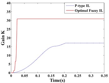
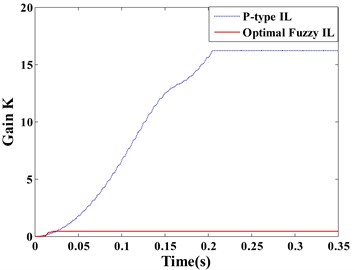
Fig. 7(a) and (b) respectively show the displacement responses of the Point A and B, it can be seen that P-type IL control cannot achieve vibration suppression in short term. Because over a thousand of iterations lead to the learning speed of feedback gain slow. However, the optimal fuzzy IL control performs a fast suppression for structural vibration in a short period, which makes it more efficient by compared with P-type IL control when the system disturbed by an impulsive excitation. Due to the symmetry of the piezoelectric smart structure and the excitation location, the sensor , , and generate the same control feedback signals in the process of vibration. The feedback gains of actuator , , and have the same learning process, as shown in Fig. 7(c). Fig. 7(d) presents the learning process of the feedback gain in actuator e.
Fig. 7Displacement response: a) point A, b) point B; learning process of feedback gain K: c) actuator a/b/c/d, d) actuator e
a)
b)
c)
d)
4.2. Harmonic excitation
When the piezoelectric smart plate is vibrating in fundamental mode 1, the displacement amplitude will theoretically be infinite for continuous steady state excitation in the time domain. The first mode control is tested in this simulation by applying the harmonic force at the Point A, where the first natural frequency 559.97 rad/s (89.122 Hz).
The optimal values of fuzzy query table are presented in Table 10, and values that change dramatically are circled by dotted line.
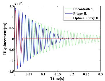
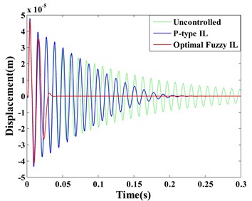
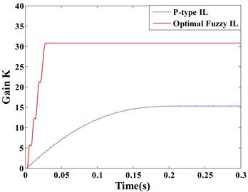
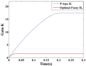
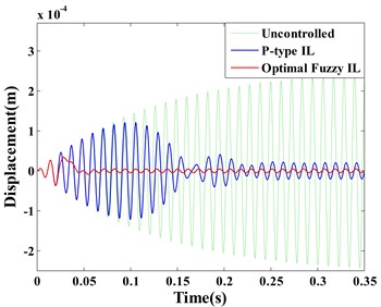
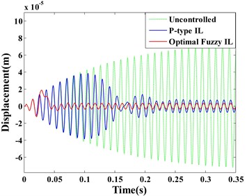
Fig. 8(a) and (b) respectively displayed the displacement responses of Point A and B, it can be seen that both the optimal fuzzy IL control and the P-type IL control present a good control effectiveness on suppression of the first vibration mode not only at the locations of sensors (e.g. Point A) but also at positions without sensors (e.g. Point B). However, it is noteworthy that these results are different from Saleh’s [12]. The paper reported that P-type IL control is just able to compensate the unwanted vibration at the observation point and is not effective at other points. Besides, it also pointed out that P-type IL control is not able to effectively suppress the structural vibration excited by its first natural frequency.
Table 10The optimal fuzzy query table for harmonic excitation
EC | E | ||||||||||||
–6 | –5 | –4 | –3 | –2 | –1 | 0 | 1 | 2 | 3 | 4 | 5 | 6 | |
–6 | –5.0 | –5.0 | –4.7 | –4.6 | –4.6 | –4.1 | –4.0 | –3.5 | –3.0 | –1.4 | –0.6 | –0.5 | 0 |
–5 | –4.9 | –4.6 | –4.6 | –4.6 | –4.5 | –3.8 | –3.1 | –3.0 | –2.1 | –0.9 | –0.1 | 0 | 0.9 |
–4 | –4.9 | –4.6 | –4.3 | –4.3 | –4.1 | –2.9 | –2.7 | –1.8 | –1.4 | –0.6 | 0 | 0 | 1.5 |
–3 | –4.7 | –4.5 | –3.6 | –3.1 | –3.0 | –2.5 | –1.4 | –1.2 | –1.2 | 0 | 0.1 | 0.5 | 1.9 |
–2 | –4.6 | –3.8 | –3.5 | –2.7 | –2.2 | –2.1 | –1.3 | –1.0 | 0 | 0.8 | 2.3 | 2.8 | 2.9 |
–1 | –4.3 | –3.5 | –3.2 | –2.6 | –1.6 | –1.1 | –0.4 | 0 | 0.5 | 1.0 | 2.4 | 2.8 | 3.4 |
0 | –3.9 | –3.3 | –2.6 | –2.1 | –1.5 | –0.1 | 0 | 0.5 | 1.3 | 1.5 | 2.4 | 3.6 | 4.3 |
1 | –2.8 | –2.7 | –2.5 | –1.9 | –1.4 | 0 | 0.7 | 1.6 | 1.7 | 3.1 | 3.6 | 3.8 | 4.6 |
2 | –2.6 | –2.6 | –2.3 | –1.6 | 0 | 0.3 | 1.9 | 2.1 | 2.5 | 3.3 | 4.2 | 4.7 | 4.8 |
3 | –1.9 | –1.3 | –1.3 | 0 | 0.4 | 1.1 | 2.0 | 2.5 | 2.6 | 3.3 | 4.5 | 4.7 | 4.9 |
4 | –1.6 | –1.0 | 0 | 1.3 | 1.3 | 1.8 | 2.3 | 2.7 | 3.9 | 3.9 | 4.5 | 4.9 | 4.9 |
5 | –0.3 | 0 | 0.2 | 1.3 | 1.6 | 2.6 | 2.7 | 3.4 | 4.0 | 4.4 | 4.8 | 4.9 | 5.0 |
6 | 0 | 0 | 0.7 | 1.5 | 2.1 | 3.8 | 4.3 | 4.5 | 4.5 | 4.7 | 4.9 | 5.0 | 5.0 |
Fig. 8Displacement response: a) point A, b) point B; learning process of feedback gain K: c) actuator a/b/c/d, d) actuator e
a)
b)
c)
d)
Effective control system is possible to attenuate the structural vibration of the entire structure rather than a small portion of the plate area. To design the vibration control system of piezoelectric smart structures, control strategy need to be considered for the desired control performance. Besides, the locations and sizes of the piezoelectric actuators and sensors also have a great influence on the control performance [44]. The areas of structure at which the mechanical strain is highest are always the best locations of actuators and sensors. In addition, the dimensions of actuators should be defined appropriately, which can ensure actuators produce the desired control forces to suppress the structural vibration. The sizes of sensors should also be chosen properly so that accurate information of structural deformation on the certain areas of the structure can be obtained. A misread of measured signal by the sensor may result in unreasonable control force generated, which may deteriorate the dynamic behavior.
In this simulation, P-type IL control presents a good effectiveness on first mode control when the locations and the sizes of actuators and sensors are selected appropriately. Furthermore, either the locations of sensors or the positions without sensors on the smart plate provide a good controllability in structural vibration.
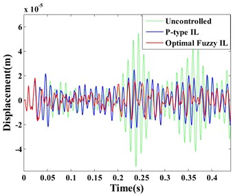
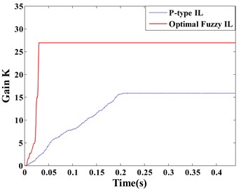
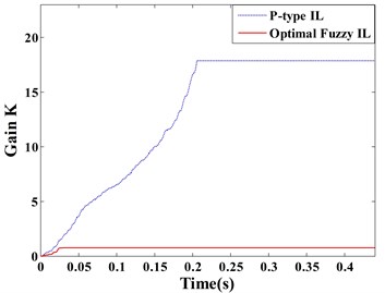
Observing the displacement responses of Point A and B (Fig. 8(a) and (b)), the vibrations suppressed by optimal fuzzy IL control have the smaller amplitude by comparing with P-type IL control. In this paper, the root mean square (RMSs) of amplitude at Point A and B are used to quantitatively evaluate the control effectiveness of the optimal fuzzy IL control and the P-type IL control. The data that is used to calculate the RMSs of amplitude start to be recorded after learning process of the P-type IL control is terminated, and the RMSs of amplitude for different simulations (except case 1) are given in Table 11. Fig. 8(c) and (d) respectively depict the learning processes of the feedback gains of the actuator a/b/c/d and actuator e.
Table 11RMSs of amplitude
Algorithm | Case 2 | Case 3 | ||
Point A | Point B | Point A | Point B | |
Uncontrolled | 1.65×10⁻⁴ | 4.89×10⁻⁵ | 6.04×10⁻⁵ | 1.81×10⁻⁵ |
P-type IL | 1.47×10⁻⁵ | 5.21×10⁻⁶ | 3.24×10⁻⁵ | 1.04×10⁻⁵ |
Optimal fuzzy IL | 3.44×10⁻⁶ | 2.47×10⁻⁶ | 1.34×10⁻⁵ | 6.68×10⁻⁶ |
4.3. Random excitation
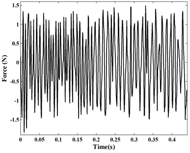
In the last simulation, a random excitation (shown as Fig. 9) is applied on the Point A to drive the piezoelectric smart plate in this simulation.
The optimal fuzzy query table is displayed in Table 12, and dotted lines are used to mark the values changed obviously. According to the update rule of the P-type IL control in Eq. (3), learning gain is fixed constant. The selection of learning gain is always based on the knowledge and experience of researchers. A larger value for learning gain may directly cause control spillover or even system instability, which makes the reduction of system robustness [14]. A smaller value for learning gain is needed to achieve the satisfying control precision. However, the smaller the learning gain are, the more iterations are necessary which leads to learning speed of feedback gain slow [10, 13]. For accelerating the learning speed of feedback gain, the learning gain can be adjusted adaptively by choosing directly from the fuzzy query table in the process of active vibration control. In order to obtain the desired control precision, the ABC searching is used to find the optimal parameters of the fuzzy logic controller.
Fig. 9The random excitation
In Table 2, the areas of zero values can be seen as a boundary that divides the table into two parts. The values in left part of Table 2 are negative, while the values are positive in right part. Combining Table 9, Table 10, Table 12 and Table 2, most of zones that the values changed notable occur in the vicinity of zero values after searching optimum solution by ABC. Notice that the values around the boundary in the fuzzy query table contribute considerably to the control precision of system.
Table 12The optimal fuzzy query table for random excitation
EC | E | ||||||||||||
–6 | –5 | –4 | –3 | –2 | –1 | 0 | 1 | 2 | 3 | 4 | 5 | 6 | |
–6 | –5.0 | –5.0 | –4.7 | –4.6 | –4.6 | –4.1 | –4.0 | –3.5 | –3.0 | –1.4 | –0.6 | –0.5 | 0 |
–5 | –4.9 | –4.6 | –4.6 | –4.6 | –4.5 | –3.8 | –3.1 | –3.0 | –2.1 | –0.9 | –0.1 | 0 | 0.9 |
–4 | –4.9 | –4.6 | –4.3 | –4.3 | –4.1 | –2.9 | –2.7 | –1.8 | –1.4 | –0.6 | 0 | 0 | 1.5 |
–3 | –4.7 | –4.5 | –3.6 | –3.1 | –3.0 | –2.5 | –1.4 | –1.2 | –1.2 | 0 | 0.1 | 0.5 | 1.9 |
–2 | –4.6 | –3.8 | –3.5 | –2.7 | –2.2 | –2.1 | –1.3 | –1.0 | 0 | 0.8 | 2.3 | 2.8 | 2.9 |
–1 | –4.3 | –3.5 | –3.2 | –2.6 | –1.6 | –1.1 | –0.4 | 0 | 0.5 | 1.0 | 2.4 | 2.8 | 3.4 |
0 | –3.9 | –3.3 | –2.6 | –2.1 | –1.5 | –0.1 | 0 | 0.5 | 1.3 | 1.5 | 2.4 | 3.6 | 4.3 |
1 | –2.8 | –2.7 | –2.5 | –1.9 | –1.4 | 0 | 0.7 | 1.6 | 1.7 | 3.1 | 3.6 | 3.8 | 4.6 |
2 | –2.6 | –2.6 | –2.3 | –1.6 | 0 | 0.3 | 1.9 | 2.1 | 2.5 | 3.3 | 4.2 | 4.7 | 4.8 |
3 | –1.9 | –1.3 | –1.3 | 0 | 0.4 | 1.1 | 2.0 | 2.5 | 2.6 | 3.3 | 4.5 | 4.7 | 4.9 |
4 | –1.6 | –1.0 | 0 | 1.3 | 1.3 | 1.8 | 2.3 | 2.7 | 3.9 | 3.9 | 4.5 | 4.9 | 4.9 |
5 | –0.3 | 0 | 0.2 | 1.3 | 1.6 | 2.6 | 2.7 | 3.4 | 4.0 | 4.4 | 4.8 | 4.9 | 5.0 |
6 | 0 | 0 | 0.7 | 1.5 | 2.1 | 3.8 | 4.3 | 4.5 | 4.5 | 4.7 | 4.9 | 5.0 | 5.0 |
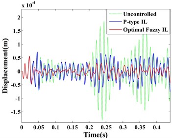
Fig. 10Displacement response: a) point A, b) point B; learning process of feedback gain K: c) actuator a/b/c/d, d) actuator e
a)
b)
c)
d)
The dynamic displacement responses of Point A and B are given in Fig. 10 (a) and (b), respectively. The learning processes of the feedback gains for the actuator a/b/c/d and actuator e are depicted in the same figure. Comparing between the optimal fuzzy IL control and the P-type IL control, the real-time variations of feedback gains are shown in Fig. 10(c) and (d).
It is important to remark that the feedback gains of the same actuators stop at different values, when the system are controlled by two methods. Considering the uncertainty of the mutual effect among all actuators, ABC algorithm is applied to determine values of fuzzification parameters and defuzzification parameters. Combining with Fig. 10(a) and (b), the optimal fuzzy IL control in this simulation presents a better control performance by comparing with the P-type IL control. In the process of active vibration control, ABC is able to make neighboring actuators to interact with each other positively such that an excellent control performance can be obtained. The similar effects like this simulation can be observed in Fig. 7 and Fig. 8.
5. Conclusions
The optimal fuzzy IL control, an intelligent learning-based approach, is developed for active vibration control in piezoelectric smart structures. In order to accelerate the learning speed of feedback gain in P-type IL controller, the learning gain is adjusted adaptively by the fuzzy logic controller. For improving the control performance, enhancing the robustness of the fuzzy logic controller and diminishing human intervention in the operation process, ABC algorithm is used to tune automatically the parameters of the fuzzy logic controller. The fuzzy logic controller is integrated into the FE model by using APDL approach, and the main program of the ABC algorithm is operated in MATLAB. The vibration control equations of piezoelectric smart structures are developed based on the dynamic FE equations of a linear elastic system. Numerical results are compared with the corresponding results using the P-type IL control approach.
It is pertinent to mention that as long as the locations and sizes of actuators and sensors are appropriately selected, both the optimal fuzzy IL controller and the P-type IL controller have a good control effectiveness on vibration suppression when the piezoelectric smart plate is excited by its first natural frequency. Furthermore, the entire piezoelectric smart plate presents a good controllability rather than small portions bonded with piezoelectric sensors by using either the optimal fuzzy IL control or the P-type IL control. These conclusions are different from Saleh’s [12].
The optimal fuzzy IL control accelerates the learning speed of feedback gain, this advantage makes the proposed control law more suitable for system disturbed by an impulsive excitation, which makes the proposed control approach very useful for applications in structures with various disturbance characteristics. However, the P-type IL control cannot effectively suppress structural vibration in the same loading condition. Comparing control performances, it is found that, unlike P-type IL control, the optimal fuzzy IL control can completely suppress structural vibration. In other words, using the proposed control approach, the disadvantages of P-type IL control given in [10, 13, 14] are overcame.
Although the optimal fuzzy IL control is applied for a plate structure in this paper, considering all advantages presented here, this approach can be applied for other structures, like beam structures, extending possibilities of its engineering and research applications.
References
-
Li X. F., Xu J. X., Huang D. Q. An iterative learning control approach for linear systems with randomly varying trial lengths. IEEE Transactions on Automatic Control, Vol. 59, Issue 7, 2014, p. 1954-1960.
-
Uchiyama M. Formulation of high-speed motion pattern of a mechanical arm by trial. Transactions of the Society of Instrument and Control Engineers, Vol. 14, Issue 6, 1978, p. 706-712, (in Japanese).
-
Arimoto S., Kawamura S., Miyazaki F. Bettering operation of dynamic systems by learning: a new control theory for servomechanism or mechatronics systems. Proceedings of 23rd Conference on Decision and Control, Las Vegas, 1984, p. 1064-1069.
-
Xiao T. F., Li X. D., John K. L. H. An adaptive discrete-time ILC strategy using fuzzy systems for iteration-varying reference trajectory tracking. International Journal of Control, Automation, and Systems, Vol. 13, Issue 1, 2015, p. 222-230.
-
Cao Z. X., Zhang R. D., Yang Y., Lu J. Y., Gao F. R. Discrete-time robust iterative learning Kalman filtering for repetitive processes. IEEE Transactions on Automatic Control, Vol. 61, Issue 1, 2016, p. 270-275.
-
Liu L., Tan K. K., Putra A. S., Lee T. H. Compensation of hysteresis in piezoelectric actuator with iterative learning control. International Conference on Advanced Intelligent Mechatronics, Suntec Convention and Exhibition Center, Singapore, 2009, p. 1300-1305.
-
Xu J. X., Huang D. Q., Venkatakrishnan V. Extreme precise motion tracking of piezoelectric positioning stage using sampled-data iterative learning control. IEEE Transactions on Control Systems Technology, Vol. 21, Issue 4, 2013, p. 1432-1439.
-
Freeman C. T., Tan Y. Iterative learning control with mixed constraints for point-to-point tracking. IEEE Transactions on Control Systems Technology, Vol. 21, Issue 3, 2013, p. 604-616.
-
Zhu X. J., Gao Z. Y., Huang Q. Z., Yi J. C. ILC based active vibration control of smart structures. IEEE International Conference on Intelligent Computing and Intelligent Systems, Vol. 2, 2009, p. 236-240.
-
Tavakolpour A. R., Mailah M., Intan Z., Darus M., Tokhi O. Self-learning active vibration control of a flexible plate structure with piezoelectric actuator. Simulation Modelling Practice and Theory, Vol. 18, 2010, p. 516-532.
-
Fadil M. A., Jalil N. A., Darus I. Z. M. Intelligent PID controller using iterative learning algorithm for active vibration controller of flexible beam. IEEE Symposium on Computers and Informatics, 2013, p. 80-85.
-
Saleh A. R. T., Mailah M. Control of resonance phenomenon in flexible structures via active support. Journal of Sound and Vibration, Vol. 331, 2012, p. 3451-3465.
-
Tayebi A., Islam S. Adaptive iterative learning control for robot manipulators: Experimental results, Control Engineering Practice, Vol. 14, 2006, p. 843-851.
-
Wang J., Li B. Fuzzy gain p-type iterative learning controller based on FPGA. Chinese Control and Decision Conference, 2011, p. 3199-3203.
-
Sharma M., Singh S. P., Sachdeva B. L. Modal control of a plate using a fuzzy logic controller. Smart Materials and Structures, Vol. 16, 2007, p. 1331-1341.
-
Yang T., Qiu W., Ma Chadli Y. M., Zhang L. X. Fuzzy model-based predictive control of dissolved oxygen in activated sludge processes. Neurocomputing, Vol. 136, 2014, p. 88-95.
-
Aouaouda S., Chadli M., Boukhnifer M., Karimi H. R. Robust fault tolerant tracking controller design for vehicle dynamics: A descriptor approach. Mechatronics, Vol. 30, 2015, p. 316-326.
-
Lu L. Y., Lin C. C., Lin G. L., Lin C. Y. Experiment and analysis of a fuzzy-controlled piezoelectric seismic isolation system. Journal of Sound and Vibration, Vol. 329, 2010, p. 1992-2014.
-
Hu C., Jing H., Wang R. R., Yan F. J., Chadli M. Robust H∞ output-feedback control for path following of autonomous ground vehicles. Mechanical Systems and Signal Processing, Vol. 70, Issue 71, 2016, p. 414-427.
-
Bououden S., Chadli M., Karimi H. R. An ant colony optimization-based fuzzy predictive control approach for nonlinear processes. Information Sciences, Vol. 299, 2015, p. 143-158.
-
Bououden S., Chadli M., Allouani F., Filali Salim A new approach for fuzzy predictive adaptive controller design using particle swarm optimization algorithm. International Journal of Innovative Computing, Information and Control, Vol. 9, 2013, p. 3741-3758.
-
Marinaki M., Marinakis Y., Stavroulakis G. E. Fuzzy control optimized by multi-objective particle swarm optimization algorithm for vibration suppression of smart structures. Structural and Multidisciplinary Optimization, Vol. 43, 2014, p. 29-42.
-
Marinaki M., Marinakis Y., Stavroulakis G. E. Vibration control of beams with piezoelectric sensors and actuators using particle swarm optimization. Expert Systems with Applications, Vol. 38, 2011, p. 6872-6883.
-
Naidu K., Mokhlis H., Baker A. H. A., Terzijia V. Performance investigation of ABC algorithm in multi-area power system with multiple interconnected generators. Applied Soft Computing, Vol. 57, 2017, p. 436-451.
-
Ma H. P., Ye S. G., Simom D., Fei M. Conceptual and numerical comparisons of swarm intelligence optimization algorithms. Soft Computing, Vol. 21, 2017, p. 3081-3100.
-
Taherdangkoo M., Bagheri M. H. A powerful hybrid clustering method based on modified stem cells and fuzzy C-means algorithms. Engineering Applications of Artificial Intelligence, Vol. 26, 2013, p. 1493-1502.
-
Cheng M. Y., Cao M. T., Tran D. H. A hybrid fuzzy inference model based on RBFNN and artificial bee colony for predicting the uplift capacity of suction caissons. Automation in Construction, Vol. 41, 2014, p. 60-69.
-
Cheng M. Y., Cao M. T. Hybrid intelligent inference model for enhancing prediction accuracy of scour depth around bridge piers. Structure and Infrastructure Engineering, Vol. 11, Issue 9, 2015, p. 1178-1189.
-
Zamani A. A., Bijami E., Sheikholeslam F., Jafrasteh B. Optimal fuzzy load frequency controller with simultaneous auto-tuned membership functions and fuzzy control rules. Turkish Journal of Electrical Engineering and Computer Sciences, Vol. 22, 2014, p. 66-86.
-
Lim Y. H. Finite-element simulation of closed loop vibration control of a smart plate under transient loading. Smart Materials and Structures, Vol. 12, 2003, p. 272-286.
-
Zhang S. Q., Li H. N., Schmidt R., Müller P. C. Disturbance rejection control for vibration suppression of piezoelectric laminated thin-walled structures. Journal of Sound and Vibration, Vol. 333, 2014, p. 1209-1223.
-
Ray M. C., Reddy J. N. Active damping of laminated cylindrical shells conveying fluid using 1-3 piezoelectric composites. Composite Structures, Vol. 98, 2013, p. 261-271.
-
Kapuria S., Yasin M. Y., Hagedorn P. Active vibration control of piezolaminated composite plates considering strong electric field nonlinearity. AIAA Journal, Vol. 53, Issue 3, 2015, p. 603-616.
-
Karagülle H., Malgaca L., Öktem H. F. Analysis of active vibration control in smart structures by ANSYS. Smart Materials and Structures, Vol. 13, 2004, p. 661-667.
-
Dong X. J., Meng G., Peng J. C. Vibration control of piezoelectric smart structures based on system identification technique: Numerical simulation and experimental study. Journal of Sound and Vibration, Vol. 297, 2006, p. 680-693.
-
Liu J. Y., Zanchetta P., Degano M., Lavopa E. Control design and implementation for high performance shunt active filters in aircraft power grids. IEEE Transactions on Industrial Electronics, Vol. 59, Issue 9, 2012, p. 3604-3613.
-
Ahn H. S., Chen Y. Q., Moore K. L. Iterative learning control: brief survey and categorization. IEEE Transactions on Systems, Man, and Cybernetics-Part C: Applications and Reviews, Vol. 37, Issue 6, 2007, p. 1099-1121.
-
Zhao D. H., Liu Y., Li H. N. Self-tuning fuzzy control for seismic protection of smart base-isolated buildings subjected to pulse-type near-fault earthquakes. Applied Sciences, Vol. 7, Issue 2, 2017, p. 185.
-
Zorić N. D., Simonović A. M., Mitrović Z. S., Stupar S. N., Obradović A. M., Lukić N. S. Free vibration control of smart composite beams using particle swarm optimized self-tuning fuzzy logic controller. Journal of Sound and Vibration, Vol. 333, 2014, p. 5244-5268.
-
Chen L. X., Cai G. P., Pan J. Experimental study of delayed feedback control for a flexible plate. Journal of Sound and Vibration, Vol. 322, 2009, p. 629-651.
-
Qian F. Numerical Modelling and Optimization of Laminated Piezoelectric Smart Structure Active Vibration Control. Ph.D. Thesis, Hefei University of Technology, Hefei, China, 2011.
-
Peng X. Q., Lam K. Y., Liu G. R. Active vibration control of composite beams with piezoelectric: a finite element model with third order theory. Journal of Sound and Vibration, Vol. 209, 1998, p. 635-650.
-
Chaiyatham T., Ngamroo I. A bee colony optimization based-fuzzy logic-PID control design of electrolyzer for microgrid stabilization. International Journal of Innovative Computing, Information and Control, Vol. 8, Issue 9, 2012, p. 6049-6066.
-
Zorić N. D., Simonović A. M., Mitrović Z. S., Stupar S. N. Optimal vibration control of smart composite beams with optimal size and location of piezoelectric sensing and actuation. Journal of Intelligent Material Systems and Structures, Vol. 24, Issue 4, 2012, p. 499-526.
About this article

The work is supported by National Natural Science Foundation of China under Grant No. 10577015.
