Abstract
Present work establishes a new formulation to determine the dynamic characteristics of a cracked beam, where the change in second moment of area is considered. The present formulation considers the shift in the neutral axis of the cracked beam-element, which has been ignored previously. Consequently, an in-depth analysis is conducted to understand the effectiveness of this new approach. The results obtained shows a promising scope for the adoption of the updated formulation for various cross-sections and future research work.
1. Introduction
The field of dynamic analysis has been of great interest for two decades among researchers. The study and interpretation of dynamics for simple structures provides the necessary knowledge to understand the behaviour of these structures, especially when they encounter discontinuities such as a crack. The primary step in any dynamic analysis of a structure is to establish a finite element model. However, the most challenging step in any finite element formulation is to obtain the best approximation of the physical model. The current work includes an update to the formulation of a cracked beam that gives a more accurate solution, which can be referred to as a benchmark for other simple or built-up structures.
Khaji et al. [1] presented an analytical approach for crack identification procedure in uniform cracked beams based on bending vibration measurements. The proposed analytical method considering Timoshenko beam theory is validated with the numerically obtained by the finite-element method. Mia et al. [2] studied the modal parameters for both cracked and uncracked cantilever beam using abacus software for different depth, position and opening of the crack. Conclusions on the failure criteria with different mode of vibrations are made. Yuen [3] observed a particular trend in the changes of Eigen value and Eigen vector with respect to the location and depth of crack. A finite element model of a uniform cross sectioned cantilever beam was chosen to provide data for analysis. Khnaijar and Benamar [4] presented a new discrete physical model to approach the problem of cracked beam vibrations. Parametric study facilitating the diagnostics process involving both crack localization and depth estimation are made.
The previous literatures ignore the shift in the neutral axis of the cracked beam-element with respect to neutral axis of the beam. Hence, the results so obtained are deemed to be mere approximations. In the present work, a new finite element formulation is established for the first time. The new formulation incorporates parallel axis theorem to determine the dynamic characteristics of the beam, effectively. This formulation is established and detailed in Section 2. In order to validate this new approach, an example of a cracked beam with rectangular cross-section is considered and its dynamic characteristics are studied and reported in Section 3. Further, Section 4 explains broader observations inferred from the conducted parametric study. Thus, the present work sheds light on the improvement observed and it is evident that the results obtained must be adopted for further research.
2. Mathematical model and formulation
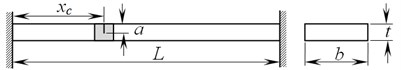
For the purpose of projected parametric study, a simple fixed-fixed beam of rectangular cross-section is considered as shown in Fig. 1. The beam is discretized into number of equal elements. Two degrees-of-freedom at each node point of every element is considered, viz., transverse and rotation, with the slope of the elastic curve, at each node.
Fig. 1Fixed-fixed beam with crack
Equation of motion of a beam for free-vibration in matrix form is given by [7]:
For non-trivial solutions the determinant of the co-efficient of must be zero:
Stiffness and mass matrices of each discretized element for two degrees-of-freedom are represented as follows:
For the un-cracked beam-element, is given by:
For a cracked beam-element, in most of the reported literature, one can find that the stiffness () is modified in order to predict the natural frequencies. One such modification is considering the second-moment of area of cross-section of the portion below the crack. At the same time, mass-loss due to crack is assumed to be zero, as it is very small when compared to the entire mass of the beam. The modified second moment of area for cracked beam-element (say, ) is represented as:
where, is ratio of crack-depth to thickness for th element.
However, this formulation failed to consider the shift in the neutral axis of the cracked beam-element with respect to the neutral axis of the beam. This leads to a significant variation in predicting the natural frequencies at different modes. This issue is addressed and reported in the present work. The present work highlights the variation in the natural frequency prediction using the new approach.
To account for the shift in the neutral axis, an effective second moment of area () is derived using parallel axis theorem as follows:
3. Comparison of and formulations for second moment of area
In order to conduct a parametric study of cracked beams, an Aluminium beam of rectangular cross-section is considered. Fixed-Fixed boundary condition is applied. A crack on the beam is taken into consideration at various positions and with varying depth as well. The beam geometry and its material properties are shown in Table 1.
A MatLab code is developed that incorporates both and formulations separately. The position of the crack on the beam () is varied along the length and the natural frequencies of up to three modes are generated. The natural frequencies are further plotted against the position of crack with respect to the length of the beam ().
Table 1Beam material (Aluminium 6082) property and geometry
Parameters | Notation | Value |
Breadth | 30 mm | |
Thickness | 10 mm | |
Length | 500 mm | |
Young’s modulus | 71 GPa | |
Density | 2,710 kg/m3 |
3.1. First natural frequency plots
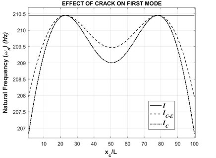
The first natural frequency for different crack positions with a crack depth to thickness ratio () of 0.2 is plotted below in Fig. 2.
Fig. 2First natural frequency with respect to varying crack position (τ= 0.2)
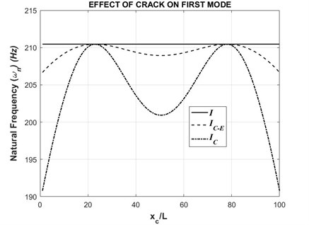
Further, the similar graph is plotted for first mode with a crack depth to thickness ratio () of 0.5. The graph is shown as follows in Fig. 3.
From the above graphs, it is observed that the natural frequencies generated when is used shows significant variations with respect to the crack position. Such a trend is highly unlikely to be observed in a practical situation. Whereas when formulation is used, the natural frequencies show nominal variations, which is a realistic scenario in practical situations.
However, it is also observed that the natural frequencies obtained from both methods meet at particular points of crack position. This non-linear variation of deviation in natural frequency is actually dependent on the mode shape. This is explained in detail in Section 4.
Fig. 3First natural frequency with respect to varying crack position (τ= 0.5)
3.2. Second natural frequency plots
As shown above in Section 3.1, the same trend follows in the case of the second natural frequencies. Similarly, the graphs are plotted for natural frequencies against the crack positions. Initially, crack depth to thickness ratio () of 0.2 is considered. The graph for this case is shown below in Fig. 4.
Fig. 4Second natural frequency with respect to varying crack position (τ= 0.2)
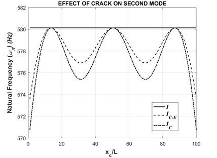
Fig. 5Second natural frequency with respect to varying crack position (τ= 0.5)
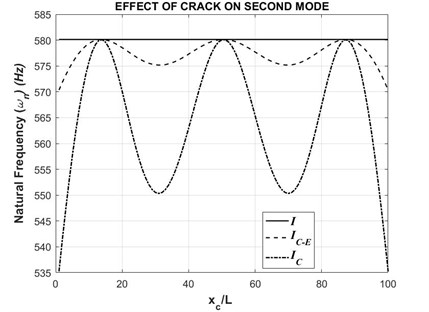
As indicated earlier, the above graph shows the same behaviour. The natural frequencies obtained from the formulation shows much more variations when compared to the formulation. Similarly, when a crack depth to thickness ratio () of 0.5 is considered, the same behaviour continues. The graph is shown below in Fig. 5.
Hence, it is evident that the incorporation of to calculate the second moment of area of a cracked beam is the correct method. The previously adopted formulation is incorrect and is just a mere approximation of the second moment of area of a cracked beam. Thus, the updated formulation must be adopted in further calculations.
4. Mode based deviation in natural frequency
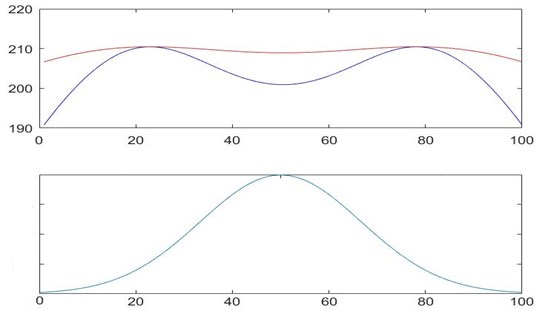
In Section 2, a new formulation to calculate the second moment of area of a cracked beam is established. The formulation is proved to be better at predicting the results with the help of graphs. It is observed from these graphs that the natural frequencies meet at a point, for a particular crack position. Away from these points, the natural frequencies deviate from each other. Such non-linear variation behaviour is actually dependent on the mode shape. The first mode shape of a fixed-fixed beam is shown in Fig. 6.
For the first mode shape of the beam, it is observed that the slope of the beam with respect to its equilibrium position is the least at exactly three regions i.e., the two boundaries and the region of maximum deflection (0.5). Further, as we move away from the boundary regions towards the centre of the beam, the slope changes. It is observed from Fig. 6 that the slope is maximum at exactly two regions. Thus, it can interpreted that the natural frequency is lesser at the regions where slope of the beam is least. Whereas, the natural frequency is comparatively higher at the regions where slope of the beam is maximum. This trend follows for both and formulations. Analogues to this the same behaviour is seen with the second mode.
Fig. 6First mode shape comparison with natural frequency plot
5. Conclusions
In the field of structural dynamics, modelling the discontinuities such as cracks must incorporate the change in stiffness. Previously reported literatures failed to consider the modified second moment of area which is caused by the shift in the neutral axis of the cracked beam-element with respect to the neutral axis of the beam. This challenge is overcome by establishing a new finite element formulation which considers parallel axis theorem to accommodate the shift in neutral axis. This new approach to effectively model discontinuous structures is exemplified by considering a fixed-fixed cracked beam with rectangular cross-section. The results are reported, and the new formulation is proved to be more effective than the previously adopted methods.
References
-
Khaji N., Shafiei M., Jalalpour M. Closed-form solutions for crack detection problem of Timoshenko beams with various boundary conditions. International Journal of Mechanical Sciences, Vol. 51, 2009, p. 667-681.
-
Md. Shumon Mia, Md. Shahidul Islam, Udayan Ghosh Modal analysis of cracked cantilever beam by finite element simulation. Procedia Engineering, Vol. 194, 2017, p. 509-516.
-
Yuen M. M. F. A numerical study of the eigenparameters of a damaged cantilever. Journal of Sound and Vibration, Vol. 103, Issue 3, 1985, p. 301-310.
-
Khnaijar Ahmed, Benamar Rhali A new model for beam crack detection and localization using a discrete model. Engineering Structures, Vol. 150, 2017, p. 221-230.
About this article

