Abstract
As the mine gearbox working conditions are poor, the fault signal is weak and usually drowned in background noise when gearbox occurring fault. The fault feature is very difficult to extract. Aiming at solving this problem, this paper proposed a mine gearbox fault feature extraction method which combines multiwavelets decomposition with maximum correlated kurtosis deconvolution (MCKD).The component of multiwavelets decomposing was processed by MCKD method, MCKD suppress the noise in the signal and enhance the weak impact feature of fault signal, the envelope of its deconvolution signal was calculated, then the fault could be judged by analyzing the prominent frequency component of envelope spectrum. Thus, the experiment analysis and engineering application verify the effectiveness of the proposed method.
1. Introduction
Mine gearbox works in a harsh environment, which results in serious environmental noise influences on the vibration signal that collected by the sensor. The signal contains large interference components, thus the impact component produced by the fault is very weak. Based upon the above reasons, the fault feature extraction from the vibration signal will be difficult, and the difficulty of the gear fault diagnosis is also increased. How to extract the effective impact fault feature information from the noisy vibration signal is the key to diagnose the fault of gearbox.
Multiwavelets is a new development of wavelet theory, relative to single wavelet and other single basis functions, it has many excellent properties which single wavelet can’t simultaneously have, multiwavelets can simultaneously have the orthogonality, compact support, symmetry and high vanishing moments and other excellent properties [1], which are very important in signal processing. They provide the premise for mechanical fault feature extraction accuracy, reliability and comprehensiveness, make multiwavelets have a considerable advantage in early fault and weak fault diagnosis. Kaewarsa et al. [2] combined multiwavelets with neural networks, and has achieved good results in power quality identification and classification. Translation-invariant multiwavelets denoising using neighboring coefficients is applied to the diagnosis of gearbox test bench and rolling bearing in [3], Sun Hai-liang et al. [4] applied multiwavelet denoising with adaptive block thresholding to gearbox diagnosis of rolling mills, both achieved good results. Chen Jing-long et al. [5] studied the application of adaptive redundant multiwavelets in fault diagnosis, HE Shui-long et al. [6] studied the application of adaptive multiwavelets via lifting scheme in bevel gear fault diagnosis, the results verify the superiority of multiwavelets in fault diagnosis.
The noisy non-stationary vibration signal of gearbox was decomposed into several different frequency band components by multiwavelets; Selecting the component that contains the main fault feature for spectrum analysis, it is difficult to extract the fault feature frequency from each component due to the influence of noise. McDonald [7] proposed the maximum correlation kurtosis deconvolution(MCKD) method, which uses signal correlation kurtosis maximization as optimization objective, to highlight the continuous pulse sequence of operational results. MCKD can improve effectively the periodic impulse component in the signal when the signal-to-noise ratio is very low, and suppress the noise, thereby achieve signal denoising and improve the kurtosis of original signal.
The original non-stationary vibration signal is decomposed, and then the appropriate frequency bands or components are selected for deep information mining, which is commonly used for fault diagnosis. This paper proposes a fault diagnosis method of multiwavelets combining MCKD. The component of multiwavelets decomposition is processed by MCKD method, suppress the noise in the signal, enhances the weak impact feature of fault signal, calculates the envelope of its deconvolution signal, then the fault could be judged by analyzing the prominent frequency component of envelope spectrum. Experiment analysis and engineering application verify the effectiveness of proposed method.
2. Multiwavelets decomposition
Multiwavelets is a wavelet which is generated by two or more than two functions as the scale function, the multi-scale function and the multiwavelets function of multiwavelets which satisfy the following two-scale matrix equation [8]:
where and are dimension coefficient matrix, is the dimension of multiwavelets.
Multiwavelets have many base functions with different time-frequency characteristics, and its decomposition and reconstruction is a multi-input and multi-output system. But most collected signals are one-dimensional data in the actual signal processing, which need to be preprocessed before multiwavelets transform, converting one-dimensional input signal to multi-dimensional vector input. Accordingly, after reconstructing multiwavelets, it needs to use postprocessing to transform multi-dimensional vector output to one-dimensional output signal, postprocessing process is generally the inverse process of the corresponding preprocessing [9]. Preprocessing has two methods, which are repeated sampling and critically non-repeated sampling, when applied to the feature extraction, the preprocessing method of repeated sampling can get better effect [10]. In this paper, we choose the method of repeated sampling.
Similar to single wavelet decomposition and reconstruction, the discrete multiwavelets decomposition and reconstruction equation are as follows:
where is low pass filter coefficient, is high pass filter coefficient; – -dimensional low frequency component; – -dimensional high frequency component.
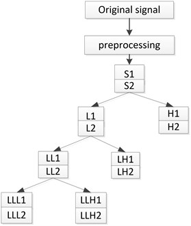
Fig. 1 shows the multiwavelets decomposition process when r is two, decomposition level is three [11]. S1 and S2 are signal sequences after the original one-dimensional signal pretreatment. S1 and S2 obtains the low-frequency part of the L1, L2 and the high frequency part of the H1, H2 after the first level decomposition, the low frequency part of L1 and L2 obtains low-frequency part LL1 and LL2 and high-frequency part of LH1 and LH2 after the second level multiwavelets decomposition, Again the low frequency part of LL1 and LL2 obtains low-frequency part LLL1 and LLL2 and high-frequency part of LLH1 and LLH2 after the third level multiwavelets decomposition. As multiwavelets dimension r is two, with two basis functions, so low frequency and high frequency have two branches after each level decomposition.
Fig. 1Frame of multiwavelets decomposition
3. Maximum correlation kurtosis deconvolution [12-14]
3.1. Correlation kurtosis
In order to extract the periodically impact fault feature in the signal, maximum correlation kurtosis deconvolution algorithm make correlation kurtosis maximum of the filtered signal by selecting a finite impulse response filter, to achieve the purpose of highlight the signal impact component.
The correlation kurtosis expression is:
In the equation, is the periodic impact signal, is the period of signal , and is the shift order. Using high order shift order can improve the ability of fault detection, increasing shift order can increase the sequence impulse number of this deconvolution algorithm, values generally take 1-7.
Correlation kurtosis is proposed at the base of kurtosis, when the cycle parameter is equal 0, correlation kurtosis translates to kurtosis, However, kurtosis is easily affected by single or a small number of high amplitude pulses in the signal. Correlation kurtosis considers fully the cycle characteristics of impact component in the signal, which suits more to measure the proportion of pulse sequence with the specific period, comparing with the kurtosis, and correlation kurtosis emphasizes more the continuity of impact component.
3.2. Maximum correlation kurtosis deconvolution
Assuming that is a continuous impact signal, is the decay response that impact signal through surrounding environment and the transmission path. is actually collected signal, the above process can be expressed as the following equation:
In order to facilitate the analysis without considering the influence of environmental noise , the essence of MCKD algorithm is to find a finite impulse response (FIR) filter, which can restore the original input signal through the output signal :
Wherein, is the filter coefficient. indicates the length of the finite impulse response filter.
In order to make the deconvolution results highlight the continuous sharp pulse, the algorithm uses signal correlation kurtosis as the evaluation criteria, and maximize it as the objective function for achieving optimal results:
Solving the above optimization problem is equivalent to solving the equation:
The filter coefficients obtained in the form of matrix are as follows:
where:
The filter coefficient is brought into the Eq. (6), and the deconvolution signal of the actual collected signal can be obtained, that is the original impact signal.
3.3. MCKD realization process
Summing up the above analysis can summarize that the realization step of MCKD algorithm is as follows:
(1) First, determine the deconvolution period parameter , the shift order and the filter length .
(2) Calculate , and according to the actual measured signal ,
(3) Use Eq. (6) to calculate the filtered signal,
(4) Calculate and through ,
(5) Obtain new filter coefficient according to Eq. (9),
(6) Compare the correlation kurtosis variation amount of before and after filtering with threshold value , if ,then return step (3), Otherwise end the whole cycle, Wherein the threshold is a small positive number, it is used to control the number of iterations.
(7) The final deconvolution signal can be obtained by the Eq. (6).
4. Multiwavelets and MCKD diagnosis method
As mine gearbox working environment is harsh, the vibration signal is seriously disturbed by the noise, and the impact feature is weak, MCKD algorithm uses signal correlation kurtosis maximization as optimization objective, which considers fully the cycle characteristics of impact component in the signal, and enhances the continuous pulse covered by the strong noise, so it is suitable to deal with weak gearbox fault signal with low signal-to-ratio and periodic impact. The collected gearbox vibration signal is non-stationary signal, and the amplitude modulation and frequency modulation phenomenon often exist simultaneously, which form complex side frequency components in the spectrum, and usually need to carry out demodulation analysis.
Multiwavelets have many excellent features that single wavelet doesn’t have, have many wavelet bases, and have stronger matching ability with fault feature. Choosing the frequency band component of the multiwavelets decomposition for targeted analysis, which can provide the premise for the accuracy and reliability of the fault feature extraction.
In conclusion, the gearbox vibration signal is decomposed by multiwavelets, obtaining several different frequency band components. This paper selects a component that containing fault feature information, to carry out MCKD denoising analysis, and to seek the envelope spectrum of the denoised signal, to extract fault feature frequency and have more accurate fault identification. The realization flow of this method is shown in Fig. 2.
Fig. 2Diagnosis flow chart

Its specific diagnosis steps are as follows:
(1) Through multiwavelets decomposition of the original gearbox vibration signal, obtains several different frequency band components;
(2) Reconstruct the component which contains fault feature by Multiwavelets;
(3) Carry on MCKD analysis to reconstructed signal;
(4) Carry on envelope demodulation analysis to MCKD denoised signal, seek the envelope spectrum;
(5) Compare the frequency of prominent amplitude with the theoretical fault characteristic frequency in the envelope spectrum, then judges the fault type of the gearbox.
5. Experiment analysis
5.1. Local broken tooth fault of gearbox test bench
Gearbox test bench gear modulus is 1.5, the number of gear teeth of input shaft is 29, the number of gear teeth of intermediate shaft is 100, the number of fault gear teeth is 36, the number of gear teeth of output shaft is 90. Test bench fault gear is local broken tooth gear which has been processed, fault gear is located in the intermediate shaft, gear transmission system driving gear of the secondary stage meshing. Use the vibration acceleration sensor collect the signal at the test bench bearing cover, the sampling frequency is 5120 Hz, input shaft gear rotational speed is 584 r/min, the rotational speed of the intermediate shaft fault gear is 169 r/min, that is, the gear fault characteristic frequency is 2.82 Hz.
Table 1The rotational speed of shafts and the meshing frequency of gearbox
Shaft | Rotational speed (r/min) | Rotational frequency (Hz) | Meshing frequency (Hz) |
Input shaft I | 584 | 9.74 | 282.4 |
Intermediate shaft II | 169 | 2.82 | 282.4, 101.6 |
Output shaft III | 67.8 | 1.13 | 101.6 |
Fig. 3Local broken tooth fault gear
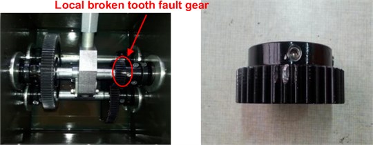
Fig. 4Time domain waveform of gearbox vibration signal
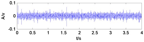
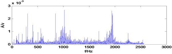
Fig. 5Spectrum of gearbox vibration signal
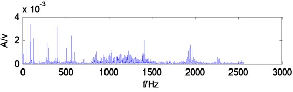
Waveform is messy from gearbox vibration signal time-domain waveform, which has no obvious periodic impulses produced by local broken teeth fault, and gearbox vibration signal frequency components of frequency spectrum are very complicated, so that it also can’t find obvious characteristic frequency components.
Take the gearbox vibration signal for multiwavelets decomposition, decomposition level is 3, and multiwavelets selects the GHM multiwavelets. The low-frequency signal of the third level is reconstructed for spectrum analysis, from spectrum (Fig. 6) can be seen, the main frequency components do not appear the component associating with the fault feature frequency, and the frequency which amplitude is most prominent is 101.5 Hz, which is similar to secondary meshing frequency 101.6 Hz, may determine is secondary meshing gears existing fault, Secondary meshing refers to the intermediate shaft and output shaft gears, particularly which gear is disabled can’t be judged. The reconstructed signal don’t make MCKD denoising, but directly make Hilbert transform and calculate envelope spectrum, which can be seen from the envelope spectrum (Fig. 7), and the frequency components which amplitude is prominent are scarce, only appear 11.5 Hz, 22.5 Hz components, which are similar to four times frequency (11.28 Hz), eight times frequency (22.56 Hz) of fault characteristic frequency 2.82 Hz, Except that there is no other fault correlation frequency components, shows when the gearbox vibration signal does not have denoising processing, it is difficult to extract the fault characteristic frequency directly to carry on envelope analysis after multiwavelets decomposition.
Fig. 6The third level low frequency signal spectrum of multiwavelets decomposition
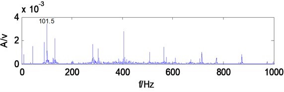
Fig. 7The third level low frequency signal envelope spectrum of multiwavelets decomposition
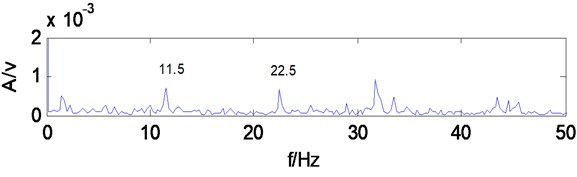
Fig. 8Envelope spectrum of MCKD signal
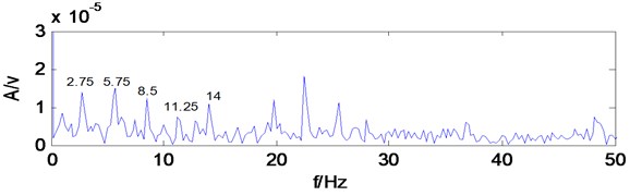
Take the low-frequency reconstruction signal of multiwavelets decomposition for MCKD analysis, period , filter length 100, shift number 2. make Hilbert transform for the denoised signal and calculate envelope spectrum, as shown in Fig. 8, the frequency components that amplitude are prominent increase significantly, 2.75 Hz, 5.75 Hz, 8.5 Hz, 11.25 Hz, 14 Hz and other frequency components were obviously highlighted, are similar to local broken tooth fault gear of intermediate shaft rotational frequency 2.82 Hz, two times frequency (5.64 Hz),three times frequency (8.46 Hz), four times frequency (11.28 Hz), which can infer secondary meshing driving gear of intermediate shaft exists fault, consistent with the reality. It shows MCKD analysis suppressing the interference components in the signal, and enhancing the weak impact fault feature in the signal, can extract the fault feature of gearbox.
5.2. Broken tooth fault of gearbox test bench
Replace the local broken tooth gear with broken tooth gear, the other parameters are kept unchanged, Analyze the same test signal.
Gearbox vibration signal time-domain waveform is messy, no obvious periodic impulses produced by broken teeth fault, and frequency components of frequency spectrum are very complicated, which also can't find obvious feature frequency components.
Fig. 9Broken tooth fault gear
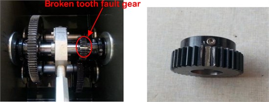
Fig. 10Time domain waveform of gearbox vibration signal
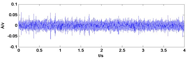
Fig. 11Spectrum of gearbox vibration signal
Take the gearbox vibration signal for multiwavelets decomposition, decomposition level is 3, Multiwavelets selects the GHM multiwavelets. The low-frequency signal of the third level is reconstructed for spectrum analysis, from spectrum (Fig. 12) can be seen, the main frequency components whose amplitude is prominent are 203.3 Hz, 304.8 Hz, 406.3 Hz, which are similar to two times, three times, four times of the secondary meshing frequency 101.6 Hz, may determine is secondary meshing gears existing fault, secondary meshing refers to the intermediate shaft and output shaft gears, and particularly which gear is disabled can’t be judged. The reconstructed signal don’t make MCKD denoising, but directly make Hilbert transform and calculate envelope spectrum, which can be seen from the envelope spectrum (Fig. 13), the frequency components which amplitude is prominent are 2.75 Hz, 5.75 Hz, 8.5 Hz, 17 Hz, 19.75 Hz, are similar to one times frequency (2.82 Hz), two times frequency (5.64 Hz), three times frequency (8.46 Hz), six times frequency (16.92 Hz), seven times frequency (19.7 Hz) of fault feature frequency 2.82 Hz, Except that there is no other fault correlation frequency components, which shows when the gearbox vibration signal does not have MCKD denoising processing, and it can extract the broken tooth fault feature frequency from the envelope after multiwavelets decomposition. But the mussy spectral line is more obvious in the envelope, exists stronger other irrelevant frequency components.
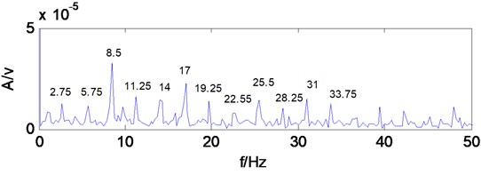
Take the low-frequency reconstruction signal of multiwavelets decomposition for MCKD analysis, period 1816, filter length 100, shift number 2 make Hilbert transform for the denoised signal and calculate envelope spectrum, as shown in Fig. 14, the frequency components whose amplitude is prominent increase significantly, 2.75 Hz, 5.75 Hz, 8.5 Hz, 11.25 Hz, 14 Hz, 17 Hz, 19.75 Hz, 22.55 Hz, 25.5 Hz, 28.25 Hz, 31 Hz, 33.75 Hz and other frequency components were obviously highlighted, are similar to broken tooth fault gear of intermediate shaft rotational frequency 2.82 Hz, two times frequency (5.64 Hz),three times frequency (8.46 Hz), four times frequency (11.28 Hz), five times frequency (14.1 Hz), six times frequency (16.92 Hz), seven times frequency (19.74 Hz), eight times frequency (22.56 Hz), nine times frequency (25.38 Hz), ten times frequency (28.2 Hz), eleven times frequency (31.02 Hz), twelve times frequency (33.8 Hz),which can infer secondary meshing driving gear of intermediate shaft which exists fault, consistent with the reality. Fig. 14 compared with Fig. 13, the extracted feature frequencies are more obvious, and there are no other irrelevant frequencies component in the spectral line, which shows that MCKD analysis suppresses the interference components in the signal, enhances the weak impact fault feature in the signal, and can extract the broken tooth fault feature of gearbox.
Fig. 12The third level low frequency signal spectrum of multiwavelets decomposition
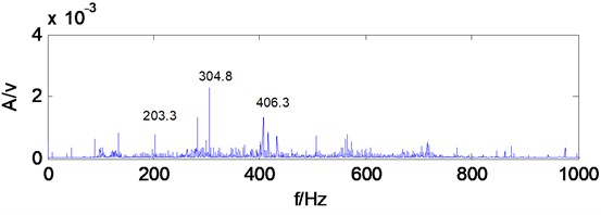
Fig. 13The third level low frequency signal envelope spectrum of multiwavelets decomposition
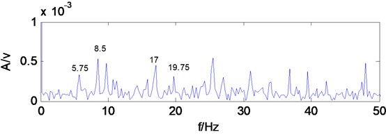
Fig. 14Envelope spectrum of MCKD signal
6. Engineering application
The working conditions of coal shearer are poor, and the impact load is serious, once the fault occur, it will cause the entire coal mine production system paralysis. Cutting unit transmission system is an important part of the shearer, and its operating conditions directly affect the safety of shearer. Therefore, carrying out necessary fault diagnosis on shearer transmission system of gearbox, has important practical significance to ensure the safety production of coal mine and prevent the occurrence of unexpected accidents.
A coal mine electrical traction shearer type is MG200/500, the transmission system structure of shearer cutting unit is shown in Fig. 15, the output torque of the motor reached planetary reducer through a series of gear transmission, finally output by the planetary frame of planetary reducer, the power is transmitted to the cutting drum. Wherein the teeth number of each gear is 23, 32, 41, 23, 44, 21, 39, 39, 43, 15, 27, 69.
Obtain each shaft rotational speed and meshing frequency of shearer cutting unit transmission system by calculation [15], as shown in Table 2.
Fig. 15Schematic of shearer cutting unit
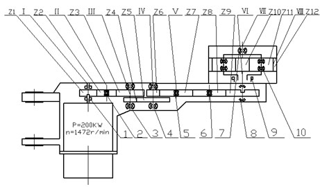
Table 2The rotational speed of shafts and the meshing frequency of gearbox
Rotational speed (r·min-1) | Rotational frequency (Hz) | Meshing frequency (Hz) |
1472 | 24.5 | 564.3 |
1058 | 17.6 | 564.3 |
825.8 | 13.8 | 564.3, 316.5 |
431.6 | 7.2 | 316.5, 151.1 |
232.4 | 3.9 | 151.1 |
232.4 | 3.9 | 151.1 |
210.8 | 3.5 | 151.1, 43.3 |
37.6 | 0.6 | = 43.3 |
In Fig. 15, the serial number 1-10 are supporting bearings of cutting unit transmission system, which chooses the bearing position to install the acceleration sensor when layout the measuring point. The working environment of shearer is harsh, damp, dusty, high gas, and it has strict requirements for voltage and current of electronic devices, need to get coal security certification, many vibration signal acquisition and recording equipment can’t be used in underground coal mine equipment which can be used on the ground, so that the vibration signal of underground equipment can’t be extracted. Therefore, China university of Mining & Technology (Beijing) invents coal mine intrinsically safe vibration acceleration sensor [16] to pick up vibration signal, signal conditioning device for mine vibration acceleration sensor [17] to amend signal, mine intrinsically safe type portable vibration recorder [18] to collect data, set the sampling frequency is 10000 Hz.
The working environment of coal shearer is poor, and its vibration signal is seriously disturbed by the noise, there is impact phenomenon in time-domain waveform. Make the shearer transmission system vibration signal for multiwavelets decomposition, decomposition level is 3, Multiwavelets selects the GHM multiwavelets. The low-frequency signal of the third level is reconstructed for spectrum analysis, which can be seen from the spectrum (Fig. 17), gearbox vibration signal frequency components are very complex, and there are no obvious feature frequency components. If the reconstructed signal don’t make MCKD denoising, directly make Hilbert transform and calculate envelope spectrum, it can be seen from the envelope spectrum (Fig. 18), the frequency components which amplitude is prominent are less, the figure appears 25.39 Hz frequency component, approximately equal to the gear Z1 of shaft 1 rotational frequency 24.5 Hz, but the amplitude is not prominent, besides found no other related fault frequency components, it is difficult to judge specific fault of gearbox accurately only through the frequency component. It indicates that when the impact characteristics associated with the fault signal is drown in the strong background noise, envelope spectrum analysis after multiwavelets decomposition is difficult to extract gearbox fault characteristic frequency.
Fig. 16Time domain waveform of shearer vibration signal
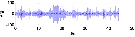
Fig. 17The third level low frequency signal spectrum of multiwavelets decomposition
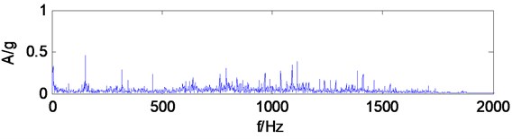
Fig. 18The third level low frequency signal envelope spectrum of multiwavelets decomposition
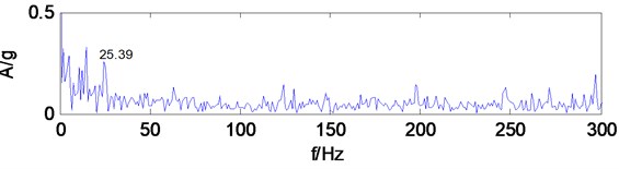
Fig. 19Envelope spectrum of MCKD signal
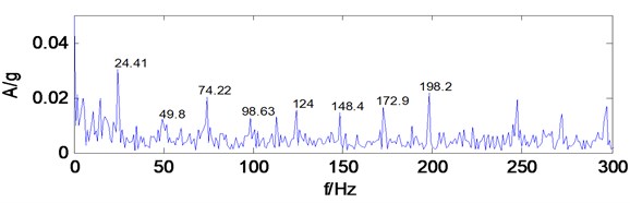
Take the low-frequency reconstruction signal of multiwavelets decomposition for MCKD analysis, after a trial comparing, period 408, filter length 100, shift number 2. the impact components in the signal is enhanced, take the denoised signal for Hilbert transform and calculate envelope spectrum, as shown in Fig. 19, the frequency components that amplitude is prominent increase significantly, 24.41 Hz, 49.8 Hz, 74.22 Hz, 98.63 Hz, 124 Hz, 148.4 Hz, 172.9 Hz, 198.2 Hz frequency components are very obvious, and the amplitude is more prominent, these frequency components are similar to gear Z1 of shaft I rotational frequency 24.5 Hz, two times frequency (49 Hz),three times frequency (73.5 Hz), four times frequency (98 Hz), five times frequency (122.5 Hz), six times frequency (147 Hz), seven times frequency (171.5 Hz), eight times frequency (196 Hz),which can infer gear Z1 of shaft I exists fault. Find that gear Z1 has wear and pitting phenomenon at overhaul, and it indicates that the diagnosis results and the actual situation are consistent. MCKD denoising method suppresses the interference components in the signal, enhances the weak impact fault characteristics of the signal, and can effectively extract the gearbox fault feature.
Shearer transmission system signal analysis results show that when the fault signal is seriously disturbed by strong background noise, it may unable to effectively extract the feature frequency information if only through the multiwavelets decomposition and the envelope analysis, but multiwavelets decomposition method combining with MCKD method process the noisy fault signal, and it can obtain the ideal processing effect, and achieve accurate diagnosis of the gearbox.
7. Conclusions
This paper proposed a fault diagnosis method of multiwavelets decomposion combing with MCKD, and gearbox test bench experiment analysis and engineering application verify the effectiveness of proposed method.
1) Multiwavelets has many scaling functions and wavelet functions, with compact support, symmetry, orthogonality and high vanishing moments and other excellent properties, which have more advantages in the mechanical fault diagnosis compared with single wavelet.
2) MCKD method can suppress the noise in the signal, achieve the purpose of noise reduction, and enhance effectively the weak compact characteristics of the signal.
3) When gearbox fault feature signal is very weak, suffering a lot from serious noise disturbance, multiwavelets decomposition combing with MCKD method are applied to the gearbox fault diagnosis, which can play their respective advantages of two methods, effectively extract the fault feature information, and realizes the accurate diagnosis of the gearbox.
References
-
Sun H. L., He Z. J., Zi Y. Y. Multiwavelet transform and its applications in mechanical fault diagnosis – a review. Mechanical Systems and Signal Processing, Vol. 43, 2014, p. 1-24.
-
Kaewarsa S., Attakitmongcol K., Kulworawanichpong T. Recognition of power quality events by using multiwavelet-based neural networks. International Journal of Electrical Power and Energy Systems, Vol. 30, Issue 4, 2008, p. 254-260.
-
Yuan J., He Z. J., Wang X. D. Translation-invariant multiwavelets denoising using neighboring coefficients and its application to monitoring and diagnosis. Journal of Mechanical Engineering, Vol. 45, Issue 4, 2009, p. 155-160.
-
Suo H. L., Zi Y. Y., He Z. J. Multiwavelet denoising with adaptive block thresholding and its application in gearbox diagnosis of rolling mill. Journal of Vibration Engineering, Vol. 26, Issue 1, 2013, p. 127-134.
-
Chen J. L., Zi Y. Y., He Z. J. Adaptive redundant multiwavelet with applications to fault diagnosis. Journal of Xi’an Jiao Tong University, Vol. 46, Issue 7, 2012, p. 44-49.
-
He S. L., Zi Y. Y., Wang Z. G. Application of adaptive multiwavelets via lifting scheme in bevel gear fault diagnosis. Chinese Journal of Scientific Instrument, Vol. 35, Issue 1, 2014, p. 148-153.
-
Mcdonald G. L., Zhao Q., Zuo M. J. Maximum correlated kurtosis deconvolution and application on gear tooth chip fault detection. Mechanical Systems and Signal Processing, Vol. 33, 2012, p. 237-255.
-
Cheng Z. X., Zhang L. L. Analysis of multiwavelet and application. Journal of Engineering Mathematics, Vol. 18, Issue 1, 2001, p. 99-107.
-
Keinert F. Wavelets and Multiwavelets. Chapman and Hall, CRC, 2004.
-
Strela V., Heller P. N., Strang G., et al. The application of multiwavelet filterbanks to image processing. IEEE Transactions of Image Processing, Vol. 8, Issue 4, 1999, p. 548-563.
-
Li D. M., Liu Z. G., Cai J., et al. Transmission lines fault recognition method based on multi-wavelet packet coefficient entropy and artificial neural network. Power System Technology, Vol. 32, Issue 24, 2008, p. 65-69.
-
Tang G. J., Wang X. L. Weak feature extraction of gear fault based on maximum correlated kurtosis deconvolution and sparse code shrinkage. Journal of Vibration Engineering, Vol. 28, Issue 3, 2015, p. 478-486.
-
Tang G. J., Wang X. L. Diagnosis method for rolling bearing incipient faults based on sparsity of envelope spectrum and maximum correlated kurtosis deconvolution. China Mechanical Engineering, Vol. 26, Issue 11, 2015, p. 1450-1456.
-
Zhong X. Y., Zhao C. L., Chen B. J., et al. Rotating machinery fault diagnosis based on maximum correlation kurtosis deconvolution and reassigned wavelet scalogram. Journal of Vibration and Shock, Vol. 34, Issue 7, 2015, p. 156-161.
-
Sheng Z. L., Yin Q. L. Technology and Application of Equipment Condition Monitoring and Fault Diagnosis. Chemical Industry Press, Beijing, 2003, p. 206-210.
-
Wu M., Xue G. H., Yang J. J., et al. A Coal Mine Intrinsically Safe Vibration Acceleration Sensor. Patent No. CN102331294, 2012.
-
Wu M., Xue G. H., Ji X. D., et al. A Signal Conditioning Device for Mine Vibration Acceleration Sensor. Patent No. CN103344320, 2013.
-
Wu M., Xue G. H., Ji X. D., et al. Mine Intrinsically Safe Type Portable Vibration Recorder. Patent No. CN103175605, 2013.
Cited by
About this article

The authors would like to acknowledge the support of Doctoral Foundation of Henan Polytechnic University (Grant No. B2017-28) and China Postdoctoral Science Foundation Funded Project (Project No. 2016M592289) and Henan Province Education Department Applied Research Project Fund (16A460005), and China National Coal Association Project (MTKJ2015-261).
