Abstract
This paper presents a test method to measure vibration characteristics of mistuned bladed disk system. Modal analysis for the disk is to verify the precision of test bench. Further mistuned parameter identification method is proposed to introduce stiffness detuning. From this the samples can be obtained. On the other hand, the joint optimization analysis system is applied which consists of iterative response surface method and particle swarm optimization algorithm. At the same time, it is proved to have higher accuracy and better generalization ability than standard polynomial response surface method for the problem in this paper. The research results indicate that the amplitudes of optimal solution are smaller than that with random arrangement. The vibration response can be improved obviously, especially for resonance region. So, this paper has a certain universality and application value for blade arrangement based on iterative response surface joint algorithm.
1. Introduction
In the course of aircraft engine design, bladed-disk system is usually defined as symmetric circular structure. Due to machining error, uneven wear and random material properties, the deviation among different sectors exists inevitably. This deviation is called mistuning. Engine bladed-disk system is sensitive to mistuning. Energy is concentrated in fewer blades. It makes the amplitudes increase greatly and leads to high cycle fatigue failure. So, it is very important to work on the study of mistuning bladed-disk system.
The study of mistuning problem began in the 1960s. In recent decades, some achievements have been made. Whitehead et al. [1] gave a theoretical investigation of the effect of blade mistuning on the vibration of the blades induced by wakes in the incident gas flow which rotate relative to the blades in question. Ewins et al. [2] used a simplified but representative model for a mistuned bladed disk and made a series of case studies to examine in detail the influence of various parameters on the resonant response levels of each blade on the disk. Rzadkowski et al. [3, 4] formulated the equations of motion describing the linear dynamics of bladed disc assemblies and gave the numerical results for tuned and mistuned bladed discs of complex geometry. Petrov et al. [5]formulated the problem of determining of the worst mistuning patterns and treated it as an optimization problem. It is another important part that experiment research is compared with theoretical calculation. Experimental investigations on the effects of random blade mistuning on the forced dynamic response of bladed disks are analyzed [6-10].
The forced vibration amplitudes are affected by the installation sequence of mistuned blades on the disk significantly. So, it is necessary to find optimization arrangement on mistuned blades. It can be regarded as a typical combinatorial optimization problem. Intelligent optimization algorithm is the core technology to solve this kind of problem. ByeongKeun et al. [11] investigated how intentional mistuning of bladed disks reduces their sensitivity to unintentional random mistuning using genetic algorithm. Rahimi et al. [12] presented a method which calculated the forced vibration response of a mistuned system based on an exact relationship between tuned and mistuned systems and used genetic algorithm to solve an optimization problem to find the worst-case response of bladed-disk assembly. Kirkpatrick et al. [13] presented a deep and useful connection between statistical mechanics and multivariate or combinatorial optimization and a detailed analogy with annealing in solids which provides a framework for optimization of the properties of very large and complex systems.
The functional relation of some variables is usually needed to be studied to help us to know the inherent law and the nature of things in the process of solving practical problems and scientific research. So, the fitting methods are used widely in many fields. Among them response surface method is a typical one. Bucher et al. [14] carried out a fast and efficient response surface approach for structural reliability problems. Bezerra et al. [15] used response surface method as a tool for optimization in analytical chemistry. Sevant et al. [16] used response surface methodology to design a flying wing. Maran et al. [17] compared response surface methodology and artificial neural network approach towards efficient ultrasound-assisted biodiesel production from muskmelon oil. Mukhopadhyay et al. [18] used response surface identify structural damage based on multi-objective. But almost no scholars combine it and intelligent optimization algorithm to solve the problem of optimization arrangement on mistuned blades.
This article primarily presents a test method for vibration response of mistuned bladed disk system. It also consists of modal analysis and mistuned parameter identification. From this the samples can be obtained. Then the joint optimization analysis system of iterative response surface method and particle swarm optimization algorithm is applied to solve the problem in this paper. Further the results before and after optimization are compared. So, it can come to a conclusion that iterative response surface joint algorithm has higher accuracy and better generalization ability.
2. Response measurement based on experimental analysis
2.1. Modal analysis for the disk
The principle diagram of the modal test for the disk is as shown in Fig. 1. The resonance method is used for testing. The disk is excited by the vibration exciter. The output power is generated by the signal generator and needs to be enhanced by the power amplifier. In the same way, the excitation frequency can be controlled by the adjustable output power. Further it is collected by the vibration pickup and identified by the waveform which is displayed by the oscilloscope.
Fig. 1Principle diagram of the simulation of modal test

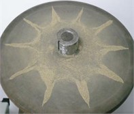
On the other hand, the vibration mode of the disk can be shown directly by the fine sand which is put on the disk evenly. The vibration of the disk is excited by the vibration exciter with different frequencies. The excitation force spreads around from the point of action. The two waves meet at the antipodal point when the excitation frequency is equal to the natural frequency of vibration. And they have the same phase. The amplitude will overlap with each other when they respectively continue to spread. The amplitudes are different in different positions. Pitch diameter or pitch circle will appear in the position of zero amplitude. And they can be shown by the movement of the fine sand.
The experiment devices of the modal test for the disk is as shown in Fig. 2. The main components contain disk, signal generator, power amplifier, vibration exciter, vibration pickup, oscilloscope, fine sand and so on. The disk is scaled down based on the actual size. It is the axisymmetric disk system whose outer diameter is 500 mm, inner diameter is 50 mm and average thickness is 10 mm. The vibration mode of plunger type is used for the vibration exciter to simulate the excitation force at the outer edge of the disk. The non-contacting installation method is used for the vibration pickup. The gap of installation is 5 mm. The fine sand is chosen carefully to keep that each diameter is less than 1 mm.
Fig. 2Experiment devices of the simulation of modal test
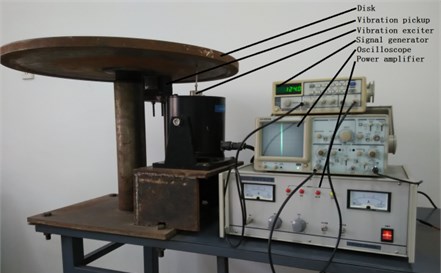
The main characteristic parameters of the experiment devices are as shown in Table 1. The signal generator can export three kinds of waveform and the output power can be changed in the range of 5 W. The power amplifier has the function of clipping, over temperature and current protection. The maximum excitation force of the vibration exciter is 10 kg. At the same time its amplitude is ±5 mm. The non-contacting installation is used for the power of the vibration pickup which is 200 W. The oscilloscope has binary channels, ALT trigger and high sensitivity. Its bandwidth is 20 MHz.
Table 1Main characteristic parameters of experiment devices
Device name | Type | Usable range / KHz |
Signal generator | SFG-1023 | 0-3000 |
Power amplifier | GF200-4 | 0-10 |
Vibration exciter | JZQ20 | 0-2 |
Vibration pickup | DJ-20 | 0-2 |
Oscilloscope | GOS-620 | 0-20000 |
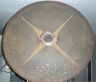
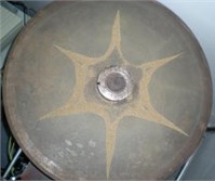
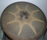
The fine sand should be placed evenly on the disk. The signal generator is used to increase the output frequency gradually. In this way, the disk can be excited by the vibration exciter with different frequencies. The stable forms of the fine sand should be recorded. At this time the fine sand will move to the minimum amplitude area or rest area from the large amplitude area. From this the pitch diameter or pitch circle is formed. The test vibration modes of the fine sand are as shown in Fig. 3.
Fig. 3Test vibration modes of fine sand
a)
b)
c)
d)
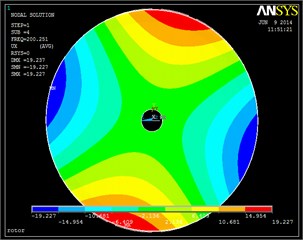
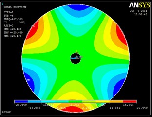
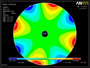
Further the finite element analysis is used in order to verify the accuracy of the test. The geometric model of cross section of the disk is established in the first place. Then mesh the model. Finally, the whole finite element model is generated by scanning and rotating the cross section. The material of the disk is taken for 45 steel. Its elasticity modulus, Poisson ratio and density are defined as 2.1×10¹¹ Pa, 0.3 and 7850 kg/m3. The boundary conditions are considered that the axial and circumferential nodal displacement of the center of the disk is fixed, at the same time the radial nodal displacement is free based on the installation of the test bench.
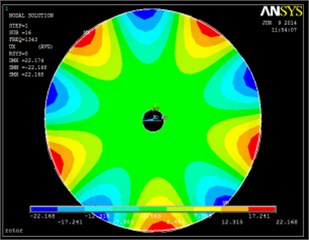
The natural frequency and modal vibration mode can be obtained by using the finite element method based on the above analysis. The corresponding vibration modes are chosen to be shown in Fig. 4. The comparison between test frequency and calculated frequency is shown in Table 2 and Fig. 5.
Fig. 4Vibration modes based on finite element method
a)
b)
c)
d)
Table 2Comparison of test and calculated frequencies
Pitch diameter 1 | Pitch diameter 2 | Pitch diameter 3 | Pitch diameter 4 | Pitch diameter 5 | |
Test / Hz | – | 194.5 | 462.1 | 837.9 | 1329.6 |
FEM / Hz | 88.998 | 200.251 | 467.163 | 848.601 | 1343 |
Error | – | 2.96 % | 1.10 % | 1.28 % | 1.01 % |
Fig. 5The comparison of test and calculated frequencies
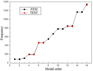
It can be seen from Fig. 3 and 4 that the vibration modes based on test method and finite element analysis are extremely similar. Also, it can be found from Table 2 and Fig. 5 that the difference between test and calculated frequencies is very little. All the errors are less than 3 %. So, it comes to a conclusion that the test bench has high precision and provides a basis for the following mistuned response analysis based on test.
2.2. Mistuned parameter identification
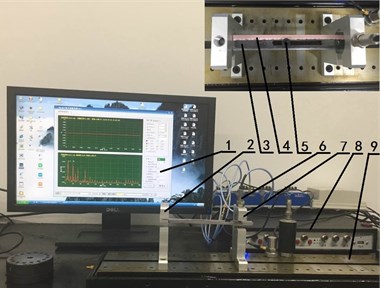
The experimental design of mistuned stiffness identification of the blade is shown in Fig. 6. The devices mainly include 1 – displacement measurement software, 2 – fixed bracket, 3 – mistuned blade, 4 – size scale, 5 – sliding mass, 6 – displacement sensor, 7 – sensor bracket, 8 – displacement signal processor, 9 – bearing surface.
The left side of the mistuned blade is fixed on the fixed bracket and the right side is free. The size scale is posted from the roots to the top of the mistuned blade and its quality is ignored. The sliding mass is 5.4 g. It is installed on the chute and can be moved from 50 mm to 130 mm which is the distance from the mistuned blade root. The width of the chute is 6 mm. Further the distance between the top of the mistuned blade and the eddy current displacement sensor is 20 mm. The displacement measurement software is used to test and record the change of the displacement of the mistuned blade. The same load is applied at the free end when the location of sliding mass is changed. In this way, the mistuned parameter can be considered for mistuned response analysis based on test.
Fig. 6Experiment design of mistuned stiffness identification
2.3. Response analysis based on test
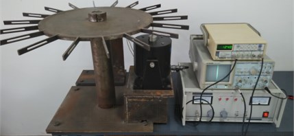
It can be seen from Fig. 7 that 18 mistuned blades are installed evenly on the edge of the disk. The thickness of the edge is 10 mm. And double rivet is used to fix each blade. The size of every blade is 162×18×6 (length×width×depth)/mm. The laser vibrometer is used to test and record the data of vibration response. Its type and usable range are PDV100 and 0-22 KHz. The vibration measurement is non-contacting and the accuracy is ±1 %.
Fig. 7Experimental measurement devices of vibration characteristic
3. Optimization arrangement on mistuned blades
The mistuned blades widely exist in the practical engineering. In this paper, the number of mistuned blades and the standard deviation of stiffness mistuning are considered to be 6 and 1 % which are shown in Table 3. From here on the data is changed to be dimensionless in order to simplify the calculation.
Table 3Stiffness mistuning of mistuned blades
No. | Stiffness mistuning | No. | Stiffness mistuning | No. | Stiffness mistuning |
1 | 0.023517859675667 | 3 | –0.00212666023859693 | 5 | 0.004138071425342 |
2 | 0.012757292038253 | 4 | –0.00154860831254031 | 6 | –0.004970036741292 |
The stiffness mistuning can be introduced by the above mistuned parameter identification method. Further 50 random arrangements are generated. The above test method is needed to obtain the vibration response. By this way 50 samples can be provided for the optimization study. The optimization object is defined as vibration localization factor which is the product of the mean and variance of vibration response.
3.1. Polynomial response surface method
6 independent variables are involved in the problem in this paper. It is requested to have high time efficiency under the condition that the accuracy satisfies a certain value. From this the polynomial response surface method [19] is considered to be applied to find the best arrangement.
The mathematical expression of response surface method are as follows:
where, is the number of design variables. , and are the coefficients of constant, primary and quadratic term. The response is considered as vibration localization factor. The expression is:
where, is vibration localization factor, is the maximum amplitude, is the number of the blades.
In this paper, quasi-newton numerical method [20] is chosen to solve the undetermined coefficients. The results are shown in Table 4.
Table 4Results of undetermined coefficients
Coefficient | Fitting | Coefficient | Fitting | Coefficient | Fitting | Coefficient | Fitting |
–0.58673 | 212.28 | 214.06 | 212.04 | ||||
–36.134 | –433.46 | 213.92 | –424.79 | ||||
6.9089 | –423.60 | 214.03 | 212.73 | ||||
7.7236 | –423.84 | 213.18 | 211.89 | ||||
7.7522 | –423.69 | –424.64 | –424.65 | ||||
7.7172 | –417.86 | 212.80 | 212.00 | ||||
7.5849 | –417.56 | 212.88 | –428.06 |
Fig. 8 shows the original data points and response surface result, where mistuning I and mistuning II are the first and second independent variable. It can be found that most of the original data points are on the response surface. But there is still a certain number of data points which are fitting below average. The fitting degree is needed to be evaluated in development. Fig. 9 is the contour plot. It shows the change of the height of the response surface.
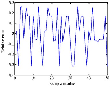
It can be seen from Fig. 10 that the trend of the two curves are almost the same. From this it can be a conclusion that the result conforms to the actual situation. On the other hand, it can be seen from Fig. 11 that the relative error is less than 30 % and has certain fluctuation. So, it is necessary to improve the fitting precision.
Fig. 8Response surface
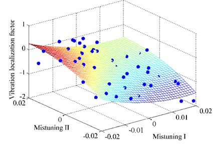
Fig. 9Contour plot
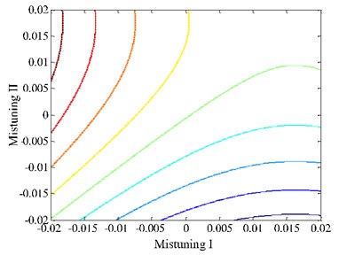
Fig. 10Comparison of sample and fitted value
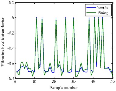
Fig. 11Relative error curve
3.2. Intelligent joint optimization algorithm
The iterative response surface joint optimization analysis system is applied in order to get higher precision. So, particle swarm optimization algorithm is considered to be applied to this problem.
Particle swarm optimization algorithm is based on the iteration. The potential solution of optimization problem need to be as a particle. First of all, a group of random particles is initialized. Each particle has a fitness value which is determined by the optimization function. Also, it has a speed which determines its flying direction and distance. It will fly to a better area and find the optimal solution finally under the attraction of individual extremum and groups of extremum.
The position and speed of the th particle in the dimensional space are and respectively. Particles update themselves by tracking two optimal solutions in each iteration.
The first is the optimal solution which the particle itself finds namely individual extremum . The other one is the optimal solution which the entire population finds namely individual extremum . In the process of looking for the two optimal solution, particles update their new positions and speeds according to the following equations:
where, is the speed of the particle; is a random number between 0 and 1; is the current position of the particle; and are learning factors. The particle swarm is made up of particles in dimensional space. Each particle is a possible solution.
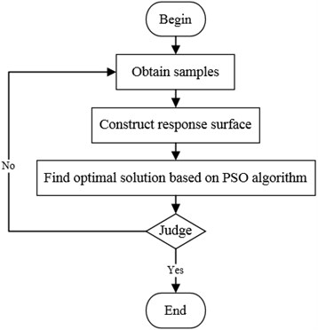
From this the optimization process can be described completely. The samples should be obtained first. Then the polynomial response surface is constructed. Its optimal solution is solved by particle swarm optimization algorithm. At this time, it should be judged to meet the accuracy requirement. If not, the current optimal solution must be one of the samples for the next optimization analysis. The operation process is as shown in Fig. 12.
Fig. 12Flow chart of iterative response surface analysis
From this the modified model of iterative response surface comes down to the following optimization problem:
where, is mistuned parameter, and are characteristic quantities of response surface and samples analysis, VLB and VUB are the boundary of the design space, is the residual error of the characteristic quantities.
Fig. 13Absolute error of coefficients
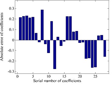
Fig. 14Response surface
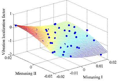
Fig. 13 is the histogram of absolute error of coefficients after iteration. It can be seen that fitting coefficients have certain change. And the range is within 0.3. So, the shape of response surface change slightly. And it can be seen from Fig. 14 that more sample points fall on the response surface.
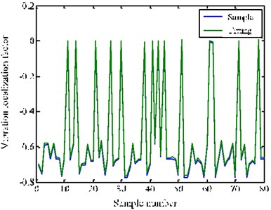
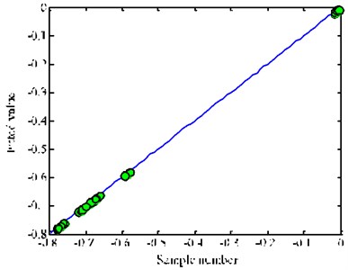
In the same way, it can be seen from Fig. 15 that there is obvious improvement in fitting precision. It is also easy to find that the data points are basically on the function curve of . This means that the iterative response surface method has higher accuracy and better generalization ability for the problem in this paper.
Fig. 15Comparison of sample and fitted value
a)
b)
3.3. Optimization results analysis
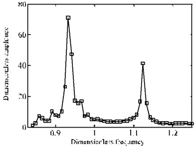
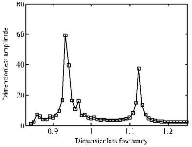
The global optimal solution can be found by using the above analysis and methods which are used in this paper. In order to show succinctly, dimensionless is introduced. The amplitude and frequency are multiplied by different constants. From this the dimensionless response of optimal solution and random arrangement has been compared as follows.
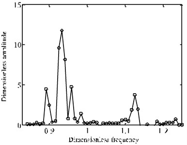
It can be seen form Fig. 16 that the amplitudes of optimal solution are smaller than that of random arrangement. Further it can be found from Fig. 17 that the reduced degree is different when frequency is changed. The change of amplitude at fundamental frequency position is larger. So, the optimization arrangement on mistuned blades has actual engineering significance based on the algorithm proposed in this paper. The vibration amplitudes can be improved obviously, especially for resonance region.
Fig. 16Comparison of frequency-amplitude cure
a) Random arrangement
b) Optimal solution
Fig. 17The change of frequency-amplitude cure before and after optimization
4. Conclusion
A test method is proposed to solve the vibration response of mistuned bladed disk system. The test method consists of modal analysis and mistuned parameter identification. In this way, the test bench can be verified and the response samples can be obtained. On the other hand, the joint optimization analysis system is proposed. It consists of iterative response surface method and particle swarm optimization algorithm. It is proved to have higher accuracy and better generalization ability than standard polynomial response surface method. The analytical results indicate that the dimensionless amplitudes obtained from the optimal solution are smaller than those from the random arrangement. The vibration response can be improved obviously, especially for resonance region. From this the optimization arrangement on mistuned blades has actual engineering and application value based on the algorithm proposed in this paper. The above study has important guiding significance for reducing the vibration of bladed-disk system.
References
-
Whitehead D. S. Effect of mistuning on the vibration of turbo-machine blades induced by wakes. Journal of Mechanical Engineering Science, Vol. 8, Issue 1, 1966, p. 15-21.
-
Ewins D. J., Han Z. S. Resonant vibration levels of a mistuned bladed disk. Journal of Vibration and Acoustics, Vol. 106, Issue 2, 1984, p. 211-217.
-
Rzadkowski R. The general model of free vibrations of mistuned bladed discs, Part I: theory. Journal of Sound and Vibration, Vol. 173, Issue 3, 1994, p. 377-393.
-
Rzadkowski R. The General Model of Free Vibrations of Mistuned Bladed Discs, Part II: Numerical Results. Journal of Sound and Vibration, Vol. 173, Issue 3, 1994, p. 395-413.
-
Petrov E. P., Ewins D. J. Analysis of the worst mistuning patterns in bladed disc assemblies. ASME Turbo Expo 2001: Power for Land, Sea, and Air, American Society of Mechanical Engineers, 2001.
-
Judge J., Pierre C., Mehmed O. Experimental investigation of mode localization and forced response amplitude magnification for a mistuned bladed disk. Journal of Engineering for Gas Turbines and Power, Vol. 123, Issue 4, 2000, p. 940-950.
-
Sever I. A. Experimental validation of turbomachinery blade vibration predictions. Applied Biochemistry and Biotechnology, Vol. 161, Issues 1-8, 2010, p. 1-21.
-
Nikolic M., Petrov E. P., Ewins D. J. Robust strategies for forced response reduction of bladed disks based on large mistuning concept. Journal of Engineering for Gas Turbines and Power, Vol. 130, Issue 130, 2008, p. 277-285.
-
Bouzit D., Pierre C. An experimental investigation of vibration localization in disordered multi-span beams. Annals of the Academy of Medicine Singapore, Vol. 187, Issue 4, 1995, p. 1565-1577.
-
Duffield C., Agnes G. An experimental investigation on periodic forced vibrations of a bladed disk. 19th AIAA Applied Aerodynamics Conference, 2001.
-
Byeongkeun C. Pattern optimization of intentional blade mistuning for the reduction of the forced response using genetic algorithm. Journal of Mechanical Science and Technology, Vol. 17, Issue 7, 2003, p. 966-977.
-
Rahimi M., Ziaeirad S. Uncertainty treatment in forced response calculation of mistuned bladed disk. Mathematics and Computers in Simulation, Vol. 7, Issue 2, 2009, p. 1-12.
-
Kirkpatrick S. Optimization by simulated annealing. Science, Vol. 220, 1993, p. 671-680.
-
Bucher C. G., Bourgund U. A fast and efficient response surface approach for structural reliability problems. Structural Safety, Vol. 7, Issue 1, 1990, p. 57-66.
-
Bezerra M. A., Santelli R. E., Oliveira E. P., et al. Response surface methodology (RSM) as a tool for optimization in analytical chemistry. Talanta, Vol. 76, Issue 5, 2008, p. 965-77.
-
Sevant N. E., Bloor M. I. G., Wilson M. J. Aerodynamic design of a flying wing using response surface methodology. Journal of Aircraft, Vol. 37, Issue 4, 2015, p. 562-569.
-
Maran J. P., Priya B. Comparison of response surface methodology and artificial neural network approach towards efficient ultrasound-assisted biodiesel production from muskmelon oil. Ultrasonics Sonochemistry, Vol. 23, Issue 123, 2015, p. 192-200.
-
Mukhopadhyay T., Dey T. K., Chowdhury R., et al. structural damage identification using response surface-based multi-objective optimization: a comparative study. Arabian Journal for Science and Engineering, Vol. 40, Issue 4, 2015, p. 1027-1044.
-
Forsberg J., Nilsson L. On polynomial response surfaces and Kriging for use in structural optimization of crashworthiness. Structural and Multidisciplinary Optimization, Vol. 29, Issue 3, 2005, p. 232-243.
-
Lai C. H. An application of quasi-Newton methods for the numerical solution of interface problems. Advances in Engineering Software, Vol. 28, Issue 5, 1997, p. 333-339.
About this article
National Science Foundation of China (Grant No. 51275081). Major Project of National Science Foundation of China (Grant No. 51335003).
