Abstract
A new mobile interface prestressed component mode synthesis (CMS) super-element method is proposed with the mobile interface prestressed and free interface super-element approach. Analysis accuracy of this method is verified by the cyclic symmetry analysis method and the direct method. The mistuning parameter of real blades is identified by modal testing and finite element method, and the vibration characteristics of the real mistuned bladed disk system are analyzed based on the mobile interface CMS method. The results showed that the maximum relative error of the dynamic frequency of tuned and mistuned examples are 0.0043 % and 0.1466 %, respectively, which can be to meet the requirement of analytical precision. Compared with the cyclic symmetry analysis method, direct method and fixed interface prestressed CMS super-element method, this method is more suitable for analyzing the vibration characteristics of arbitrary mistuned bladed disk system.
Highlights
- A mobile interface prestressed component mode synthesis (CMS) super-element method is proposed.
- Analysis accuracy of this method is verified by cyclic symmetry analysis method and direct method.
- Vibration characteristics of real mistuned bladed disk system are analyzed based on this method.
1. Introduction
Bladed disk system, as an important component of the aero-engine, its vibration characteristics directly affect the aero-engine's operational reliability and structural integrity. At present, the vibration characteristics of the bladed disk system are investigated by using the experimental and finite element numerical simulation. As the bladed disk system is large and the blade’s shape is complex, also the work loading is very large, and the vibration of some measuring points are sometimes difficult to measure while performing the overall test. Therefore, the finite element method is often used to analyze the vibration characteristics of large and complex structures such as the bladed disk system. Due to the requirement of the analytical precision, there are a large number of meshes and nodes for the bladed disk models, resulting in a large freedom of nodes. For ordinary computers, it is virtually impossible to directly solve the dynamics equations of the bladed disk models. The use of large-scale numerical simulation workstations can be time-consuming even if they can be resolved. In recent years, many scholars have considered the dynamics of complex large-scale structures extensively. The main purpose is to establish an efficient reduction method, which can effectively reduce the DOF of the system models and make the reduced order models to meet the requirements of the actual structural analysis. Guyan and irons proposed a freedom of the static reduction method [1, 2]. Paz proposed a freedom dynamic reduction method [3]. As the static reduction method is simple and practical, some scholars have proposed several mode synthesis methods. For example, Hurty proposed a fixed interface method [4]. Hou and Goldman proposed a free interface method [5, 6]. On the basis of the mode synthesis method, Wei proposed a modal super-element method [7]. Vargiu extended Component Mode Mistuning technique (CMM), referred as Integral Mode Mistuning (IMM). The proposed IMM technique is validated in terms of both modal parameters estimation and forced response calculation [8]. Lee conducted the mistuned bladed disk forced vibration analysis including a vortex lattice prediction given an external aerodynamic force based on a standing wave formulation [9]. Kan described the effect of the coriolis force on forced response magnification of intentionally mistuned bladed disk [10]. Yuan described a review of efficient computational techniques for mistuning analysis of bladed disk [11]. The cyclic symmetric method was used to analyze the vibration localized characteristics of the error frequency cycle mistuned bladed disk system [12]. The cyclic symmetric method was used to analyze the coupling vibrations of harmonic shrouded blades in a gas turbine [13]. The modal integrated super-element method was used to analyze the static frequency of the mistuned bladed disk system in the gas turbine [14]. Qin used the direct analysis to establish the whole finite element model of the mistuned bladed disk system and analyze its dynamic frequency at the working speed [15]. A prestressed CMS super-element method is put forward with the fixed interface prestressing and free interface super-element approach [16]. The modal and dynamic characteristics of the mistuned bladed disk system considering the influence of contact stress between the tenon of the blade and the mortise of the disk are analyzed based on the fixed interface prestressed CMS super-element method [17]. An improved hybrid interface substructure component modal synthesis method (HISCMSM) is proposed. Computational efficiency of the mistuned blisk can be increased observably by this method [18]. A method called multi-stage multi-objective multi-disciplinary agent model based on dynamic substructure method (MSMOMDAM-DSM) is proposed. For a large amount of calculation, it can increase the mistuned blisk’s computational efficiency more significantly comparing with the traditional probability analysis method when the request of computational accuracy is satisfied [19]. The component mode mistuning method is used for multi-stage assemblies to create a mistuning identification approach. Results show that the proposed approach is effective even for modes which are multi-stage [20].
In general, the vibration characteristics of the tuned or periodic mistuned bladed disk system can be analyzed by cyclic symmetry method, and for arbitrary mistuned bladed disk system, it can be analyzed by the mode synthesis method or the direct method. As the direct method is more time-consuming, so usually using mode synthesis method. Mode synthesis method needs to divide the bladed disk system into several substructures. The vibration characteristics and response analysis of the mistuned bladed disk system is a prestressed mode synthesis analysis of the sub-structure, which is often used for the analysis of first overall-then substructure. However, this analysis method only applies to small and medium model, it is very time-consuming while analyzing the mistuned bladed disk system and other large models. Based on the above shortcomings, a new method of mobile interface prestressed CMS super-element is proposed, which uses the analysis of elementary substructure-then overall. Analysis accuracy of this method is verified by the cyclic symmetry analysis method and the direct method. The mistuning parameter of real blades is identified by modal testing and finite element method. The vibration characteristics of a real mistuned bladed disk structure are analyzed by this method.
2. Mobile interface prestressed CMS super-element method
Firstly, assuming that the bladed disk system is a tuned system which satisfies the cyclic symmetry condition. Therefore, the cyclic symmetry analysis method is utilized to obtain the static characteristics of the bladed disk system under the working speed. Establishing the first basic sector finite element model of bladed disk, and is displacement vector of the first basic sector. Dividing the displacement vector into interface DOF, expressed by subscript , and non-interface DOF, denoted by subscript , can be expressed as:
Exerting constrained boundary, working speed and interfacial cyclic symmetry conditions, and then using the cyclic symmetry analysis to obtain the displacement vector of the first basic sector interface freedom in the bladed disk system at the working speed.
Secondly, supposing the bladed disk system as a mistuned system, which is divided into substructures. Here is the number of blades. Each basic sector of bladed disk is a substructure, and the displacement vector of the th substructure interface freedom in the bladed disk system is , which can be expressed as follows:
where is the number of nodes on the interface. The displacement vector of the th node on the interface can be expressed as:
According to the cyclic symmetry condition, the displacement vector of the th node on the ()th substructure interface in the bladed disk system can be obtained by:
The displacement vector of the ()th substructure interface freedom in the bladed disk system is , which can be expressed as follows:
where is known, substituting it into Eq. (2-5), and then are available.
The static (prestressed) equation of the th substructure in the bladed disk structure at the working speed is:
where is the stiffness matrix of the th substructure, is the load vector caused by the working speed, is the displacement vector of the th substructure. Dividing the displacement vector into the master DOF (interface DOF, denoted by subscript ) and slaver DOF (non-interface DOF, denoted by subscript ), can be expressed as:
Substituting Eq. (7) into Eq. (6), the transformed form is:
Exerting the mobile displacement constraint on the interface DOF, and then a prestressed analysis is performed. Eq. (8) is simplified that:
Solving the Eq. (9) and obtaining the corresponding centrifugal stiffness matrix caused by the rotating, and the spin-softening matrix . While considering the centrifugal stiffening and spin-softening, the total stiffness matrix of the substructure can be expressed as:
For the undamped bladed disk structure, the dynamic equation for the th substructure is established as follows:
where is the mass matrix of the substructure, is the force vector which applied to the other substructures on the substructure interface, is the external force vector on the nodes other than the substructure interface. Substituting Eq. (7) into Eq. (11), and considering the forces of nodes other than the interface when the structure is free vibration, Eq. (11) transformed form is:
A substructure analysis is performed based on the free interface mode synthesis super-element method, that is releasing the mobile displacement constraints on the interface DOF, the free vibration equation of the undamped substructure on the free interface is:
From Eq. (7), the complete master mode set of the substructure can be obtained. Adopting as complete Ritz basis, and then the displacement vector in the physical coordinates can be expressed by modal coordinate vector that:
Substituting Eq. (7) into Eq. (14) and truncating the high-order modal set in Eq. (14). Based on the low-order modal set , then Eq. (14) is approximately transformed that:
where is the truncated generalized modal coordinate vector, is the coordinate transformation matrix. Based on the free interface method, the first transformation matrix is:
where is the unit matrix, is the redundant static constraint modal matrix, is the inertia relief mode matrix. , where is the regular modal matrix of the master DOF interface, is the regular modal matrix of the slaver DOF interface. Adopting as an assumed mode of the substructure in the overall system. Substituting Eq. (15) into Eq. (12), and transforming the th dynamic Eq. (12) of the substructure in the physical coordinate into the modal coordinate. That is:
where, , . Transforming dynamic equations of substructures into those which are under the corresponding modal coordinates, and then the super-elements are generated. Combining dynamic equations of the super-element in modal coordinates of the bladed disk system, that is:
Assuming that all the super-element interfaces are rigidly connected, that is the DOF coupling of the interface nodes, then the th super element and the th connected super-element interface satisfying the displacement coordination condition and the force balance equation. The displacement coordination condition is . That is:
The force balance equation is:
Selecting as the generalized coordinates of the synthetic system, the transformation relation between the modal coordinate and the generalized coordinate is:
Here is the second transformation matrix [21], its value is determined by Eq. (19). Substituting Eq. (21) into Eq. (18), the synthetic equation of generalized coordinate can be obtained that:
where:
Substituting the force balance Eq. (20) into , simplifying it that , and Eq. (22) is simplified that:
Eq. (23) is the free vibration equation of the whole bladed disk system under the generalized coordinate which considers the effect of rotational prestressed. Obtaining the dynamic frequency of the whole bladed disk system and vibration mode in generalized coordinate by solving Eq. (23), and then completing the use analysis of super-element. By substituting the coordinate transformation Eq. (21) and Eq. (15), the vibration mode of the bladed disk system under physical coordinate can be obtained, and then completing the expansion analysis of the super-element.
3. Analysis accuracy verification
3.1. Tuned bladed disk system
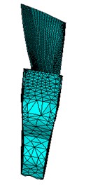
The cyclic symmetry analysis method is utilized to verify the analytical precision of mobile interface CMS super-element method. Since the cyclic symmetry analysis method is only applicable to the cyclic symmetry structures or the mistimed periodic structures, it is assumed that the bladed disk structure is tuned, that is, each blade has the same material parameters. The above two methods are used to analyze the dynamic frequency of the bladed disk system respectively. The finite element model of the basic sector and bladed disk system example is shown in Fig. 1. The working speed is 11353 r/min and the number of the blades is 12. Material parameters of the blades are: elastic modulus 2.1×10¹¹ Pa, Poisson ratio 0.3, density 4500kg/m3. Material parameters of the disk are: elastic modulus 2.1×10¹¹ Pa, Poisson ratio 0.3, density 4500kg/m3.
Fig. 1Finite element model of the basic sector and bladed disk system
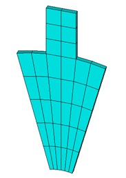
a)
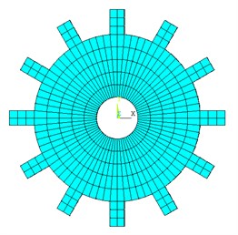
b)
3.2. Mistuned bladed disk system
The direct method is used to verify the analytical precision of mobile interface CMS super-element method based on mistuned bladed disk example. The finite element model, material parameters and working speed of bladed disk as previously described, except for the elastic modulus of the bladed disk. The elastic modulus of mistuned bladed disk is shown in Table 1.
Table 1Mistuned elastic modulus
Sector number | Elastic modulus (Pa) | Sector number | Elastic modulus (Pa) | Sector number | Elastic modulus (Pa) |
1 | 2.1×10¹¹ | 5 | 2.016×10¹¹ | 9 | 2.194×10¹¹ |
2 | 2.019×10¹¹ | 6 | 2.015×10¹¹ | 10 | 2.193×10¹¹ |
3 | 2.018×10¹¹ | 7 | 2.014×10¹¹ | 11 | 2.192×10¹¹ |
4 | 2.017×10¹¹ | 8 | 2.195×10¹¹ | 12 | 2.191×10¹¹ |
3.3. Accuracy verification results
The relative error of the dynamic frequency of the bladed disk at the working speed is:
Here is the number of nodal diameter in a tuned system or order in a mistuned system. is the dynamic frequency of the th nodal diameter in a tuned system which is obtained based on the cyclic symmetry analysis method or the th order in mistuned system which is obtained based on the direct method. is the dynamic frequency of the th nodal diameter in a tuned system or the th order in a mistuned system which is obtained based on the mobile interface CMS super-element method.
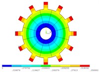
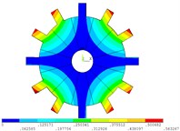
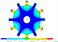
The dynamic frequency and relative error of the tuned bladed disk system at the working speed obtained by the cyclic symmetry analysis method and mobile interface CMS super-element method are given in Table 2. The maximum relative error of the dynamic frequency is 0.0043 %, which accords with the accuracy requirement. The vibration mode of the tuned system by the mobile interface prestress CMS super-element method and the cyclic symmetry analysis method is shown in Fig. 2 and Fig. 3, respectively. The vibration mode of the tuned system is the same by both two methods, but differs only in phase.
Table 2Dynamic frequency and relative error of tuned bladed disk at the working speed
Number of nodal diameter | 0 | 1 | 2 | 3 | 4 | 5 | 6 |
(Hz) | 211.47 | 231.73 | 288.69 | 368.52 | 450.86 | 513.58 | 537.12 |
(Hz) | 211.47 | 231.72 | 288.69 | 368.52 | 450.86 | 513.58 | 537.12 |
(%) | 0 | 0.0043 | 0 | 0 | 0 | 0 | 0 |
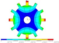
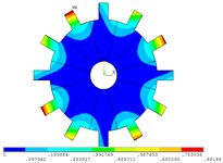
Fig. 2Vibration mode of tuned system by mobile interface prestressed CMS super-element method
a) 0 nodal diameter
b) 1 nodal diameter
c) 2 nodal diameter
d) 3 nodal diameter
e) 4 nodal diameter
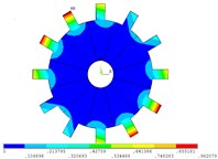
f) 5 nodal diameter
g) 6 nodal diameter
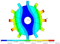
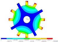
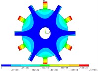
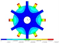
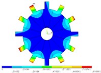
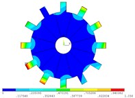
The dynamic frequency and relative error of the mistuned bladed disk system at the working speed obtained by the direct method and mobile interface CMS super-element method are shown in Table 3. The maximum relative error of the dynamic frequency is 0.1466 %, which accords with the accuracy requirement. The vibration mode of mistuned system by the mobile interface prestress CMS super-element method and the direct method is shown in Fig. 4 and Fig. 5, respectively. The vibration mode of mistuned system is the same by both two methods, and only a slight difference in phase. Therefore, regardless of tuned system or mistuned system, the mobile interface prestress CMS super-element method meets the requirements of analytical accuracy in terms of dynamic frequency and vibration mode.
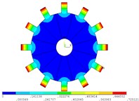
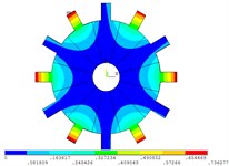
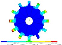
Fig. 3Vibration mode of tuned system by cyclic symmetry analysis method
a) 0 nodal diameter
b) 1 nodal diameter
c) 2 nodal diameter
d) 3 nodal diameter
e) 4 nodal diameter
f) 5 nodal diameter

g) 6 nodal diameter
Table 3Dynamic frequency and relative error of mistuned bladed disk at the working speed
Order number | 1 | 2 | 3 | 4 | 5 | 6 |
(Hz) | 211.41 | 231.64 | 231.78 | 288.64 | 288.66 | 368.37 |
(Hz) | 211.1 | 231.43 | 231.88 | 288.43 | 288.62 | 368.17 |
(%) | 0.1466 | 0.0907 | 0.043 | 0.0728 | 0.0139 | 0.0543 |
Order number | 7 | 8 | 9 | 10 | 11 | 12 |
(Hz) | 368.45 | 450.48 | 450.75 | 512.85 | 513.19 | 537.72 |
(Hz) | 368.39 | 450.46 | 450.58 | 512.65 | 513.18 | 537.98 |
(%) | 0.0163 | 0.00444 | 0.0377 | 0.039 | 0.00195 | 0.048 |
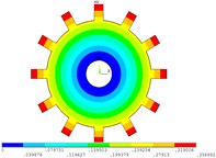
Fig. 4Vibration mode of mistuned system by mobile interface prestressed CMS super-element method
a) 1 order
b) 2 order
c) 3 order
d) 4 order
e) 5 order
f) 6 order
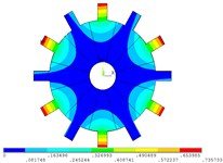
g) 7 order
h) 8 order
i) 9 order
j) 10 order
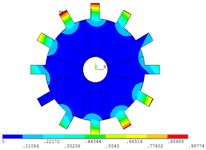
k) 11 order
l) 12 order
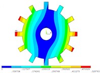
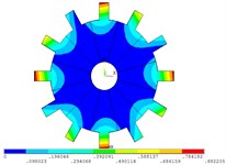
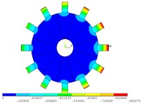
Fig. 5Vibration mode of mistuned system by direct method
a) 1 order
b) 2 order
c) 3 order
d) 4 order
e) 5 order
f) 6 order
g) 7 order
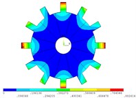
h) 8 order
i) 9 order
j) 10 order
k) 11 order
l) 12 order
4. Vibration characteristics analysis of real mistuned bladed disk system
4.1. Mistuned blades parameter identification
The bladed disk structure is usually considered to be circularly symmetrical or harmonic. But due to uneven material, processing error, use-wear or flutter suppression, in practice there is little difference in the blades, called mistuned blades [22]. Assuming that the disk is a tuned structure, the blades are led into different elastic modulus perturbation coefficients to simulate mistuned blades, as follows:
where is the elastic modulus of tuned blades, is the elastic modulus of the th mistuned blade, is the elastic modulus disturbance coefficient of the th mistuned blade, can be associated with the dynamic equation matrix [23]. While utilising the above-mentioned mobile interface CMS super-element method, Eq. (25) represents the overall stiffness of each blade as a sub-matrix and lead into a mistuned elastic modulus disturbance parameter [17]. So, it is very important to identify , and then get . The mistuned parameters of all the blades of the first-stage bladed disk system in a compressor are identified based on the method which combined with modal testing and finite element analysis. The specific identification process and modal testing system parameters is shown in [23]. Table 4 shows the mistuned elastic modulus of each blade identified by the above method.
4.2. Vibration characteristics analysis
The finite element model of the basic sector and real bladed disk system is shown in Fig. 6. The working speed of mistuned bladed disk structure is 11353 r/min and the number of blades is 38. Material parameters of the blades: mistuned elastic modulus of each blade is shown in Table 4. Poisson ratio 0.3, density = 4380 kg/m3. Material parameters of the disk: the elastic modulus 1.15×10¹¹ Pa, Poisson ratio 0.3, density 4640 kg/m3. The contact pairs are respectively provided on the tenon of the blade and the mortise of the disk. The type of contact pairs is standard contact, and the coefficient of friction is 0.1. The contact area is discretized based on the augmented Lagrangian method, and the contact analysis is performed by the implicit algorithm. The mobile interface CMS super-element method is used to analyze the dynamic frequency of the first-stage mistuned bladed disk system in a compressor.
Table 4Elastic modulus of Mistuned blades
Blade number | (Pa) | Blade number | (Pa) | Blade number | (Pa) |
1 | 1.1318×10¹¹ | 14 | 1.0701×10¹¹ | 27 | 1.1076×10¹¹ |
2 | 1.09044×10¹¹ | 15 | 1.111×10¹¹ | 28 | 1.08705×10¹¹ |
3 | 1.03653×10¹¹ | 16 | 1.0499×10¹¹ | 29 | 1.12486×10¹¹ |
4 | 1.08705×10¹¹ | 17 | 1.111×10¹¹ | 30 | 1.02987×10¹¹ |
5 | 1.12138×10¹¹ | 18 | 1.0399×10¹¹ | 31 | 1.1007×10¹¹ |
6 | 1.02987×10¹¹ | 19 | 1.111×10¹¹ | 32 | 1.02987×10¹¹ |
7 | 1.08705×10¹¹ | 20 | 1.0399×10¹¹ | 33 | 1.1007×10¹¹ |
8 | 1.03653×10¹¹ | 21 | 1.1076×10¹¹ | 34 | 1.02657×10¹¹ |
9 | 1.11795×10¹¹ | 22 | 1.1041×10¹¹ | 35 | 1.09044×10¹¹ |
10 | 1.08365×10¹¹ | 23 | 1.1076×10¹¹ | 36 | 1.02327×10¹¹ |
11 | 1.1145×10¹¹ | 24 | 1.00023×10¹¹ | 37 | 1.07685×10¹¹ |
12 | 1.00353×10¹¹ | 25 | 1.09044×10¹¹ | 38 | 0.99371×10¹¹ |
13 | 1.1145×10¹¹ | 26 | 1.12138×10¹¹ |
Fig. 6Finite element model of the basic sector and real bladed disk system
a)
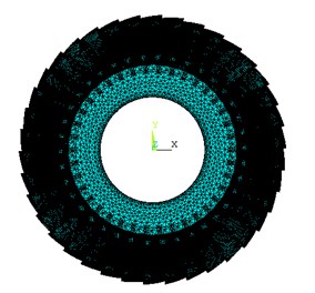
b)
4.2.1. Blade Campbell diagram
In order to better indicate the relationship between the blade frequency and rotational speed, and determine the resonance point of the blade, the blade Campbell diagram is necessary. Before drawing Campbell diagram, it must first determine the excitation order.
The number of stator blades is , and the number of rotor blades is . Then the excitation phase difference :
The phase difference of the excited vibration mode is a function of the excitation order and the rotor blade number , can be expressed as:
According to the triple point theory, one of the conditions for bladed disk resonance is that the excitation order is equal to the number of nodal diameter. That is, when the excitation phase difference and the phase difference of the excited vibration mode satisfy the following relationship, the resonance can be excited:
Here 0, 1, 2, 3, …, substituting Eq. (26) and Eq. (27) into Eq. (28):
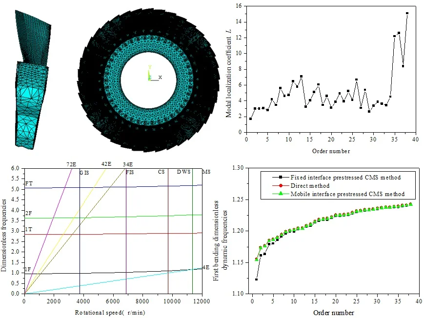
When the number of stator blades, the number of rotor blades and the excitation order satisfies Eq. (29), the blade is excited to resonate. The number of stator blades 42, and the number of rotor blades 38. According to Eq. (29), the possible excitation order 4, 34, 42, 72. It can be seen from Table 4 that the elastic modulus of No. 38 blade is the minimum, and that of No. 1 blade is the maximum. Therefore, Campbell diagrams of No. 38 blade and No.1 blade as showed in Fig. 7 and Fig. 8, respectively. In the Campbell diagram, there are five speed, namely the ground idling speed (GIS), flight idling speed (FIS), cruising speed (CS), design working speed (DWS) and the maximum speed (MS), respectively. In Fig. 7 and Fig. 8, before the flight idling speed (FIS), the engine speed is usually the transition speed, shorter residence time. So, the 34E, 42E and 72E order excitation frequency cannot provoke blade destructive resonance. However, the intersection of the 4E order excitation frequency line and the 1st order bending frequency line of the blade is near the design working speed (DWS) line, which easily causes the destructive resonance of the blade.
Fig. 7No. 38 blade Campbell diagram
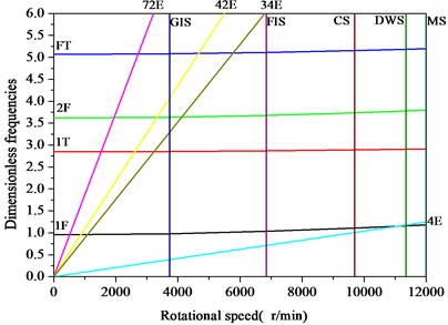
Fig. 8No. 1 blade Campbell diagram
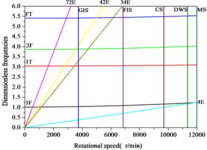
Fig. 91F Campbell diagram of No. 1 and No. 38 blade
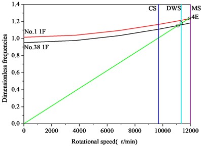
The first-order Campbell diagram of No.1 blade and No.38 blade as showed in Fig. 9. After the flight idling speed, the engine enters normal working condition. If the resonance rotational speed cannot be avoided, the engine will enter the resonance state. If the resonance energy is very strong, the engine will immediately be malfunctioning. Fig. 9 shows that the rotation speed corresponding to the intersection of the 4E order excitation frequency and the 1st order bending frequency of No. 38 blade and No. 1 blade are 11150 r/min and 11960 r/min, respectively. If the engine is operating in this speed range for a long time, it will cause resonance damage of blades. So, the vibration characteristics of the mistuned bladed disk system at the design working speed are analyzed in the next section.
4.2.2. Vibration characteristics analysis of mistuned bladed disk system
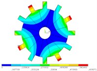
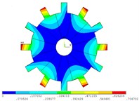
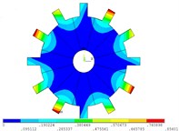
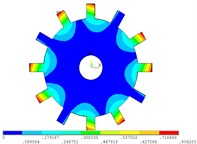
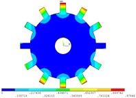
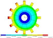
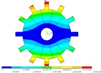
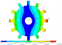
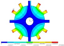
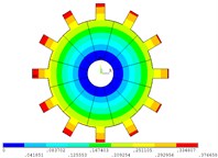
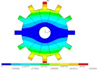
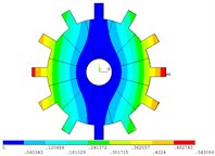
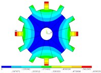
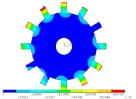
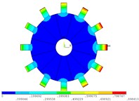
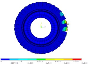
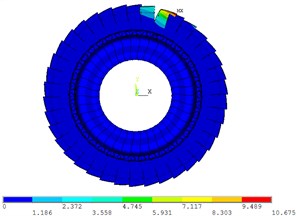
The vibration mode of real mistuned bladed disk system by the mobile interface prestress CMS super-element method is shown in Fig. 10. Due to the large mistuned amount of the blades, the vibration mode of the real mistuned bladed disk system is no longer a clear nodal diameter vibration except the first order. Fig. 10 shows that the vibration mode of mistuned bladed disk system appeared modal localization phenomenon with a different order number.
In order to analyze the influence of order number on the modal localization of the mistuned bladed disk system, the following modal localization factor is introduced [22]:
where is the blade nmuber of the rator, is the blade number of the maximum amplitude, and the maximum modal dimensionless amplitude is . The modal localization factor describes the relative difference between the maximum blade vibration energy in the bladed disk system and the average vibrational energy of the other blades. According to Eq. (30), the modal localization factor of mistuned bladed disk system-order number curve is shown in Fig. 11.
Fig. 10Vibration mode of real mistuned system by mobile interface prestressed CMS super-element method
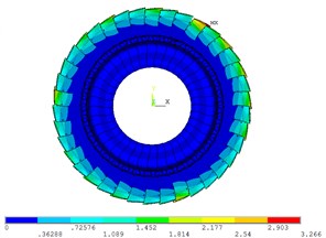
a) 1 order

b) 8 order
c) 26 order
d) 38 order
Fig. 11Modal localization factor – order number curve
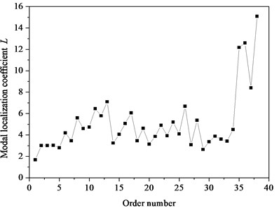
It can be observed in Fig. 10 and Fig. 11 that when the order number is 1, the vibration mode of bladed disk shows approximate 0 nodal diameter vibration, the modal localization factor 1.68 and the modal localization degree is very low. When the order number is 8, the vibration mode of bladed disk does not show 4 nodal diameter vibration. The modal localization factor 5.6, the modal localization degree is larger, and the vibration energy is concentrated on a few blades. When the order number is 26, the vibration mode of bladed disk does not show 13 nodal diameter vibration. The modal localization factor 6.7, the modal localization degree is larger, and the vibration energy is focused on the three blades. When the order number is 38, the vibrational mode of bladed disk does not show 19 nodal diameter vibration. The modal localization factor 15.1, the highest degree of modal localization and the vibrational energy are concentrated on the two blades.
The effects of mistuning on the localization degree of different order vibration modes of bladed disk system are quite different. For a particular form of mistuning, the modal localization factor curve of the mistuning system shows an oscillatory tendency with the increase of the order number. It is indicated that there are some mistuned sensitivity discrepancies in the modal characteristics of different orders for a particular form of mistuning. In this case, for a large mistuning strength, the difference between the localization degree of each vibration mode of the bladed disk system is very significant. The difference or discrepancy is closely related to the form of mistuning.
Fig. 12First bending family each order dimensionless dynamic frequencies of tuned and mistuned bladed disk system
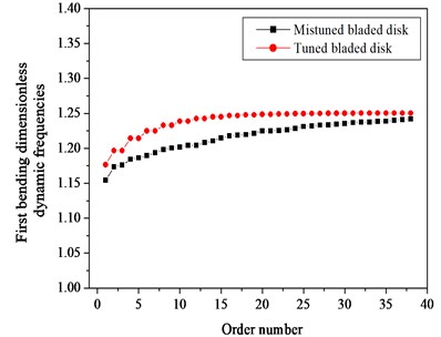
The dimensionless dynamic frequency is described as the ratio of each order dynamic frequency of the bladed disk structure to the static frequency of tuned blades. Fig. 12 is the first bending family each order dimensionless dynamic frequency of the tuned and mistuned bladed disk structure. It can be seen from Fig. 8 that the tuned bladed disk system appear reverberation phenomenon, that is, in addition to the 1 and 38 order dynamic frequencies, others appear in pairs. Due to the existence of mistuning, the mistuned bladed disk system appears a phenomenon of frequency separation, that the pair of frequencies are no longer equal. Since the elastic modulus of all mistuned blades are less than those of the tuned blades, therefore, all order dimensionless dynamic frequencies of the mistuned bladed disk structure are smaller than those of the tuned bladed disk system.
4.2.3. Accuracy analysis and comparison of various methods
The first bending family each order dimensionless dynamic frequency of the real mistuned bladed disk structure by the direct method, mobile interface prestress CMS super-element method and fixed interface prestressed CMS super-element method [16, 17] are shown in Fig. 13. It can be seen from Fig. 13 that the first bending family dimensionless dynamic frequencies result of the real mistuned bladed disk structure by mobile interface prestress CMS super-element method is close to that of the direct method. The first bending family dimensionless dynamic frequencies result of the real mistuned bladed disk structure by fixed interface prestress CMS super-element method is different from that of the direct method, especially in lower orders. The main reason for this difference is that in this paper during the prestress analysis at the working speed, the mobile displacement constraint is applied on both sides of the basic sector of the bladed disk. Under the action of centrifugal force at the working speed, the centrifugal stiffening of the blade and the disk are significant. The way of applying constraints is more in line with the actual conditions. In the literature [16] and [19], during the prestress analysis at the working speed, the fixed displacement constraint is applied on both sides of the basic sector of the bladed disk.
Fig. 13First bending family each order dimensionless dynamic frequencies of mistuned bladed disk structure by three methods
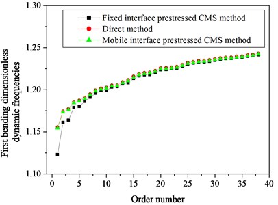
According to Saint-Venant’s principle, the influence of the fixed displacement constraint on the blade is small, but the impact on the disk is larger. So, under the action of centrifugal force at the working speed, the centrifugal stiffening of the blade is significant, but the centrifugal stiffening of the disk is not obvious. The blade total stiffness matrix of the two methods is basically the same. However, the disk total stiffness matrix of the method in this paper is obviously larger than the disk total stiffness matrix of the literature method (Compared with centrifugal stiffening, the influence of spin-softening on the stiffness matrix is relatively small). For the weakly coupled bladed disk system, the reduction of the disk total stiffness matrix leads to the stronger coupling between the blade and the disk, which have a great influence on the lower orders frequency of the bladed disk system, but have little effect on the higher orders frequency. So, the frequency error of the literature method is larger in the lower orders. Therefore, analytical accuracy of the mobile interface prestress CMS super-element method is higher than that of the fixed interface prestress CMS super-element method.
The analysis model, analysis accuracy and analysis time of four methods is shown in Table 5. The cyclic symmetry analysis method only applies to the cyclic symmetry (periodic symmetry) structure, that is the tuned or periodic mistuned bladed disk structure. The cyclic symmetry analysis method has high analytical accuracy, and not time consuming. The fixed interface prestressed CMS super-element method, mobile interface prestressed CMS super-element method and the direct method are suitable for tuned, periodic mistuned and arbitrary mistuned system. The fixed interface prestressed CMS super-element method has low analytical accuracy when the order number is low, and the analysis time is medium. The mobile interface prestressed CMS super-element method has superior analytical accuracy, and the analysis time is medium. The direct method also has sharp analytical accuracy, but the method is time consuming. Compared with the cyclic symmetry analysis method, the mobile interface prestressed CMS super-element method can lead into the different material parameters for each blade, such as the elastic modulus of mistuned blades. It can analyze not only the vibration characteristics of tuned and periodic mistuned bladed disk system, but also those of arbitrary mistuned bladed disk system. Compared with the fixed interface prestressed CMS super-element method, the mobile interface prestressed CMS super-element method has higher analytical accuracy. Compared with the direct method, the mobile interface prestressed CMS super-element method is not time consuming. In summary, this method is very suitable for analyzing the vibration characteristics of arbitrary mistuned bladed disk system.
Table 5Analysis model, analysis accuracy and analysis time of four methods
Analysis method | Analysis model | Analysis accuracy | Analysis time |
Cyclic symmetry analysis method | Tuned system √ Periodic mistuned system√ Arbitrary mistuned system × | High precision | Not time consuming |
Mobile interface prestressed CMS super-element method | Tuned system √ Periodic mistuned system√ Arbitrary mistuned system √ | High precision | Medium |
Fixed interface prestressed CMS super-element method | Tuned system √ Periodic mistuned system√ Arbitrary mistuned system √ | Low precision when the order is low | Medium |
Direct method | Tuned system √ Periodic mistuned system√ Arbitrary mistuned system | High precision | Time-consuming |
5. Conclusions
This paper proposes a mobile interface prestressed CMS super-element method in view of the shortcomings while analyzing the complex large-scale model such as mistuned bladed disk system by using the existing CMS super-element method. Analysis accuracy of the method is verified by the cyclic symmetry analysis method and the direct method. Regardless of tuned system or mistuned system, the mobile interface prestress CMS super-element method meets the requirements of analytical accuracy in terms of dynamic frequency and vibration mode. Real blades mistuned parameters were identified by modal testing and finite element method, and the vibration characteristics of a real mistuned bladed disk structure are analyzed based on the mobile interface prestressed CMS super-element method. Compared with the other three methods, this method takes into account the analysis model, analysis accuracy and analysis time, so this method is preferable to the other three methods.
References
-
Guyan R. J. Reduction of stiffness and mass matrices. AIAA Journal, Vol. 3, Issue 2, 1965, p. 380-380.
-
Irons B. M. Structural eigenvalue problems: elimination of unwanted variables. AIAA Journal, Vol. 3, Issue 5, 1965, p. 961-962.
-
Paz M. Dynamic condensation. AIAA Journal, Vol. 22, Issue 5, 1984, p. 724-727.
-
Hurty W. C. Vibration of structural system by component mode synthesis. Journal of the Engineering Mechanics Division, Vol. 86, 1960, p. 51-69.
-
Hou S. Review of mode synthesis techniques and a new approach. Shock and Vibration Bulletin, Vol. 40, Issue 4, 1969, p. 25-30.
-
Goldman R. L. Vibrations analysis by dynamic partitioning. AIAA Journal, Vol. 7, Issue 6, 1969, p. 1152-1154.
-
Wei S. T., Pierre C. Statistical analysis of the forced response of mistuned cyclic assemblies. AIAA Journal, Vol. 28, Issue 5, 1990, p. 861-868.
-
Vargiu P. C., Firrone M., Zucca S., Gola M. M. A reduced order model based on sector mistuning for the dynamic analysis of mistuned bladed disks. International Journal of Mechanical Sciences, Vol. 53, Issue 8, 2011, p. 639-646.
-
Lee I. l., Shin S. J., Kim Y. R. Mistuned bladed disk forced vibration analysis based on standing wave formulation. Aerospace Science and Technology, Vol. 24, Issue 1, 2013, p. 275-282.
-
Kan X. E., Xu Z. L., Zhao B., Zhong J. Z. Effect of Coriolis force on forced response magnification of intentionally mistuned bladed disk. Journal of Sound and Vibration, Vol. 399, 2017, p. 124-136.
-
Yuan J., Scarpa F., Allegri G., Titurus B., Patsias S., Rajasekaran R. Efficient computational techniques for mistuning analysis of bladed discs: A review. Mechanical Systems and Signal Processing, Vol. 87, 2017, p. 71-90.
-
Wang J. J., Yu C. B., Li Q. H. Localization characteristics of vibratory mode for bladed disk assemblies. Journal of Aerospace Power, Vol. 24, Issue 4, 2009, p. 788-792.
-
Zhou C. Y., Zou J. X., Wen X. Y., Sheng H. Y. Coupled vibrations of gas turbine shrouded blades. Journal of Harbin Institute of Technology, Vol. 33, Issue 1, 2001, p. 129-133.
-
Zhou C. Y., Zou J. X., Wen X. Y., Shen H. Y. Vibration characteristics analysis of mistuned blade-disc systems of gas turbine. Gas Turbine Technology, Vol. 13, Issue 3, 2000, p. 42-46.
-
Qin F., Chen L. M. Vibration analysis of mistuned bladed disc of steam turbine. Journal of Beijing University of Technology, Vol. 33, Issue 2, 2007, p. 126-128.
-
Li Z. J., Yang W. J., Yuan H. Q. Vibration analysis of aeroengine blisk structure based on a prestressed CMS super-element method. Shock and Vibration, Vol. 6, Issue 2016, 2016, p. 1-10.
-
Zhang L. Research on Vibration and Multi-Field Coupling Mechanics Characteristic of Bladed Disk System in Aero-Engine. Northeastern University, Shenyang, 2013.
-
Bai B., Bai G. C., Li C. Application of improved hybrid interface substructural component modal synthesis method in vibration characteristics of mistuned blisk. Chinese Journal of Mechanical Engineering, Vol. 27, Issue 6, 2014, p. 1219-1231.
-
Bai B., Bai G. C., Li C. Application of multi-stage multi-objective multi-disciplinary agent model based on dynamic substructural method in mistuned blisk. Aerospace Science and Technology, Vol. 46, 2015, p. 104-115.
-
Nyssen F., Epureanu B., Golinval J.-C. Experimental modal identification of mistuning in an academic two-stage drum. Mechanical Systems and Signal Processing, Vol. 88, 2017, p. 428-444.
-
Craig R. R., Bampton M. D. D. Coupling of substructures for dynamic analysis. AIAA Journal, Vol. 12, 1968, p. 1313-1319.
-
Zhang L., Yuan H. Q., Han Q. K., Yang S. M., Song L., Li Y. Vibration analysis of mistuned bladed disk system based on microslip friction model. Journal of Vibration Engineering, Vol. 25, Issue 3, 2012, p. 289-293.
-
Zhang L., Li X., Yuan H. Q. Mistuning parameter identification of blades based on modal testing and finite element method. China Measurement and Testing Technology, Vol. 41, Issue 11, 2015, p. 16-19.
About this article

This paper is supported by National Natural Science Foundation of China (No. 51505206), Liaoning Provincial Department of Education Scientific Research General Project (No. L2014246) and Liaoning University of Technology Teacher Research Start Fund Project (No. X201202).
