Abstract
Trenches, as important military defense measures, have significant practical significance in studying the impact of trench terrain on the propagation patterns of explosive shock waves. This research is based on numerical simulations and establishes six trench models with depths of 0 mm, 200 mm, 400 mm, 600 mm, 800 mm, and 1000 mm, as well as five different lengths of trenches: 400 mm, 600 mm, 800 mm, 1000 mm, and 1200 mm. The internal and front-to-back shock wave pressures within the trenches were numerically calculated. The research findings indicate that as the depth of the trench increases, the pressure at the midpoint of the trench bottom gradually decreases within a depth of 800 mm, and then slowly increases beyond 800 mm. As the length of the trench increases, the pressure on the trench bottom significantly decreases when the length does not exceed 600 mm, but steadily increases after reaching 600 mm.
1. Introduction
Explosion shock waves, as important damage factors of ammunition and warheads, are crucial indicators for evaluating the destructive effectiveness of ammunition systems and an important aspect of weapon system assessment [1-3]. Trenches, as significant military facilities, play a vital role in evaluating the power of ammunition systems and ensuring the safety protection of personnel when explosive shock waves propagate and vary inside and near trenches after explosions occur in their vicinity.
Currently, numerous domestic and foreign scholars have conducted extensive research on the propagation and distribution laws of shock wave pressure with respect to trenches. Jacob et al. [4] investigated the influence of explosive equivalent and detonation distance on the response of structures in solid-supported partially confined cylinders. Xu et al. [5] examined the effects of trench terrain on the propagation patterns of explosion shock waves, analyzed the variations in shock wave pressure for trenches of different widths and depths, as well as flat terrain. The results indicated that as the width of the trench increased, the peak pressure at the bottom of the trench initially decreased and then remained constant. Moreover, as the depth of the trench increased, the bottom pressure of the trench decreased while the specific impulse increased. Cao et al. [6] focused on studying the propagation patterns of ground-level explosion shock waves in mountainous terrain with different valley widths, obtaining the crater depths and radii for ground-level explosions in various valley widths. Kong et al. [7] utilized finite element numerical simulations to investigate the propagation rules of explosion shock waves in subway stations, demonstrating that the peak overpressure duration produced by explosives in confined spaces and the degree of damage to the surrounding environment were higher compared to atmospheric environments. Hou [8] combined theoretical analysis and numerical simulation to analyze the attenuation of fragment velocity under different terrain conditions, revealing the impact of terrain on the lethal range of anti-personnel bombs. Zhang et al. [9] conducted blast testing in a vacuum explosion tank under normal pressure and vacuum conditions, and the experiments showed that the propagation direction of explosion shock waves was significantly influenced by the vacuum environment, while under normal pressure, the destructive power of the same explosive was greater.
In this study, using finite element numerical simulation software, we constructed simulation models to analyze the distribution laws of explosion shock wave pressure under different trench lengths and depths. We investigated the influence of trench depth and length on the peak pressure of shock waves, providing theoretical support for military engineering defense against explosion shock waves.
2. Computational model and material parameters
2.1. Model establishment
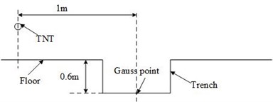
The numerical simulation analysis was conducted based on the testing scheme under actual damage conditions. The model mainly consists of the visible air domain, TNT explosives, and sand soil. A two-dimensional axisymmetric modeling approach was adopted to simplify the model algorithm. The size of the visible air domain is 20000 mm×8000 mm, with a specific grid cell size of 20 mm×20 mm. The size of the sand soil region is 20000 mm×2000 mm, with the same grid cell size as the air domain. According to typical high-energy warhead tests, a cylindrical TNT explosive weighing 50 kg was placed at the center of the air domain. The length-to-diameter ratio of the explosive column is 1:1, and the detonation was initiated at the center with a height of 2000 mm. Two sets of comparative experiments were set up: Experiment 1 focused on the impact of trench depth on explosion shock waves. The TNT explosive was placed 1 m away from the start of the trench, with a trench length of 400 mm. Trench depths of 0 mm, 200 mm, 400 mm, 600 mm, 800 mm, and 1000 mm were selected. Gaussian monitoring points were set at the middle of the trench, along the edges of the trench, and 200 mm away from the edge in the direction of the TNT explosive and the ground, resulting in a total of 5 pressure measurement points. Experiment 2 focused on the impact of trench length on explosion shock waves. The trench depth was set at 600 mm, and the trench lengths were set as 400 mm, 600 mm, 800 mm, 1000 mm, and 1200 mm. The measurement points were distributed at the middle position of the trench bottom, with a lateral distance of 1000 mm from the TNT explosive. A rigid interface was set at the bottom of the model, and outflow boundaries were applied to the left and top of the air domain to ensure normal air flow within the region and to avoid the reflection of shock waves caused by boundary conditions. The computational model is shown in Fig. 1, and the layout of sensor measurement points is illustrated in Fig. 2 and Fig. 3.
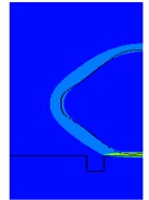
Fig. 1Finite element numerical simulation model
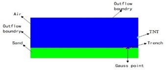
Fig. 2Layout of sensor measurement points
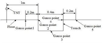
Fig. 3Layout of sensor measurement points
2.2. Material model
In the model, the TNT material in the explosive filling is described using the JWL state equ ation, as shown by the following expression [10-12]:
where, represents the pressure of TNT explosive during detonation; represents the relative volume; represents the specific internal energy of unit mass of TNT explosive; , , , , and are the five parameters of the JWL state equation, where and are material parameters, and , , and are constants. The specific forms of these parameters are shown in Table 1 [13].
The air medium is described using the ideal gas state equation, as shown by the following equation:
where, represents the pressure of the detonation products; is the adiabatic index, with a value of 1.4; represents the air density, with a value of 1.225 kg/m3; represents the initial specific internal energy of air, with a value of 2.068×10⁵ J/kg.
Table 1Parameters of explosive materials
/ kg.m-3 | / GPa | / GPa | |||
1630 | 373.7 | 3.75 | 4.15 | 0.9 | 0.35 |
3. Analysis of simulation results
3.1. Comparison of shock wave pressure curves
To characterize the influence of trenches on the overpressure of shock waves, detonations were initiated at the center of the ground surface and a trench with a length of 400 mm and a depth of 600 mm, using a 50 kg TNT explosive. The pressure-time curves of the shock waves at measurement points 3 and 5 on both the ground surface and the trench were obtained, as shown in Fig. 4.
Fig. 4Pressure curves of shock waves on flat ground and in trenches
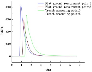
TNT explosions generate spherical waves that propagate outward. When the shock wave approaches a trench, the propagation space suddenly increases and the airflow expands continuously, creating a pressure difference between the front and back of the trench. This causes the shock wave to travel downward, impacting the interior of the trench. By analyzing Fig. 4, it can be observed that at measurement point 3 located at the center of the trench bottom, the shock wave pressure decreases relatively smoothly. The same applies to measurement point 5, but with a smaller decrease in magnitude. Meanwhile, compared to the same position inside the trench, measurement point 3 on the flat ground experiences an earlier arrival time for the peak of the shock wave. Combining this with the evolution of shock wave pressure contour maps at different times, it can be inferred that when the propagation time reaches 0.8 ms, the shock wave reaches the edge of the trench. At 1.25 ms, refraction and reflection occur within the trench, and the shock wave reaches measurement point 5 before reaching measurement point 3, reaching its peak pressure. At 1.5 ms, after propagating and undergoing successive reflections, the shock wave reaches measurement point 3, where the energy of the shock wave is focused and reaches its peak value. At the same time, at measurement point 5, the shock wave undergoes reflection and absorption by the ground, resulting in a decrease in pressure. At 1.6 ms, the shock wave pressure at measurement point 3 also begins to decrease. The time-varying shock wave pressure contour is shown in Fig. 5.
Fig. 5Pressure contour of shock wave pressure variation with time
a) 0.8 ms
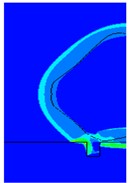
b) 1.2 ms
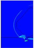
c) 1.5 ms
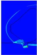
d) 1.6 ms
3.2. Influence of depth on peak overpressure of shock wave
To reflect the impact of different trench depths on the explosive shock wave, six different ground conditions were set up: a flat ground and trenches with depths of 200 mm, 400 mm, 600 mm, 800 mm, and 1000 mm, all with a length of 400 mm. The pressure of the shock wave at various measurement points was obtained, as shown in Table 2.
Table 2Peak overpressure of shock wave at different measurement points under various depths
Measurement point | Pressure / kPa | |||||
Flat ground | Trench | |||||
Depth 0.2 m | Depth 0.4 m | Depth 0.6 m | Depth 0.8 m | Depth 1 m | ||
1 | 9.79 | 9.78 | 9.78 | 9.78 | 9.78 | 9.78 |
2 | 8.31 | 4.21 | 4.22 | 4.22 | 4.22 | 4.22 |
3 | 6.13 | 5.70 | 4.28 | 3.24 | 2.53 | 2.56 |
4 | 4.94 | 10.4 | 3.82 | 3.55 | 3.55 | 3.55 |
5 | 4.46 | 3.54 | 3.54 | 3.54 | 3.54 | 3.54 |
From the table, it can be observed that the peak overpressure at measurement point 1 remains unchanged, indicating that the pressure of the shock wave on the flat ground in front of the trench is not affected. When the shock wave reaches the edge of the trench, the propagation space suddenly increases, resulting in a larger dispersed area of shock wave energy and a decrease in peak pressure. Therefore, at measurement point 2 on the trench floor, the pressure is significantly reduced compared to on the flat ground. However, as the depth of the trench increases, the peak overpressure of the shock wave at measurement point 2 on the trench floor remains unchanged. As the shock wave continues to propagate forward into the trench, reflection and refraction occur within the trench, leading to a continuous attenuation of energy and a decrease in shock wave pressure. From the table, it can be observed that at different depths in the middle of the trench bottom, the peak overpressure of the shock wave decreases compared to on the flat ground, but the extent of attenuation varies. As the depth of the trench increases, the peak pressure of the shock wave initially decreases and then increases. Additionally, it can be seen that when the depth of the trench is 200 mm, as the shock wave propagates to the back of the trench, compared to on the flat ground, the shock wave focuses within the trench, resulting in an increase in energy density and an increase in the peak overpressure of the shock wave. At measurement point 4, the shock wave pressure significantly increases compared to on the flat ground. However, as the depth increases, the internal space of the trench becomes larger, leading to more energy dispersion and a decrease in shock wave pressure. When the depth exceeds 600 mm, the pressure begins to stabilize. When the shock wave propagates to the flat ground at the rear of the trench, at the same measurement point location, the peak pressure of the shock wave decreases. As the depth increases, the pressure value remains constant, and the increasing depth has no effect on the shock wave pressure at measurement point 5.
3.3. Influence of length on peak overpressure of shock wave
In order to study the effect of trench length on the peak overpressure of the shock wave, the pressure-time curves of the shock wave at different trench lengths located at the middle position of the trench bottom with the same depth and TNT equivalent of 50 kg were obtained, as shown in Fig. 6.
Fig. 6Pressure-time curves of chock wave for trenches of different lengths
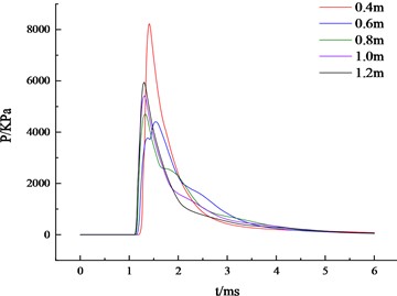
As you can see from Fig. 6, as the length of the trench increases, the shock wave overpressure peak at the same position in the middle of the trench bottom first decreases and then increases. When the trench length is 400 mm to 600 mm, the shock wave pressure continues to decline, and the length is 600 mm to 1200 mm. When the shock wave pressure starts to increase. Combined with specific data analysis, the peak pressure at the center of the bottom surface of the trench of different lengths is 8.23 KPa (400 mm), 4.41 KPa (600 mm), 4.70 KPa (800 mm), 5.42 KPa (1000 mm), 5.94 KPa (12000 mm), and the peak pressure attenuation range of the shock wave at the bottom center of the trench length is 46.42 % (600 mm), 42.89 % (800 mm), 34.14 % (1000 mm), 27.82 % (1200 mm). This indicates that for trenches of the same depth, as the length increases, the shock wave pressure at the same location in the middle of the trench bottom is not consistent. The peak overpressure of the shock wave decreases and then increases with the increase in trench length.
4. Conclusions
In this study, a finite element numerical simulation method was used to construct simulation models of explosive shock waves in trenches with different lengths and depths. The distribution pattern of the shock wave pressure at different trench depths, including the interior of the trench, both sides of the trench edges, and the front and back of the trench, was analyzed and summarized. Additionally, the variation characteristics of the pressure at the midpoint of the trench bottom were quantitatively analyzed for different trench lengths. The following conclusions were drawn:
Due to the influence of the trench topography, when the shock wave propagates into the trench, the peak overpressure at the central point of the trench bottom is lower compared to the flat ground. The time at which the peak pressure occurs at the central point of the trench bottom lags behind that of the same location on the flat ground.
With the increase in trench depth, the peak overpressure at the central point of the trench bottom gradually decreases. However, after reaching a depth of 800 mm, the pressure starts to increase, but the magnitude of the increase is limited.
The peak overpressure of the shock wave on the trench bottom exhibits a significant decrease within trench lengths up to 600 mm. When the length exceeds 600 mm, within the range of 600 mm to 1200 mm, the peak pressure gradually increases.
This research provides a theoretical basis for pressure testing of explosive shock waves in trenches with different depths and lengths.
References
-
V. Aune, G. Valsamos, F. Casadei, M. Larcher, M. Langseth, and T. Børvik, “Numerical study on the structural response of blast-loaded thin aluminium and steel plates,” International Journal of Impact Engineering, Vol. 99, pp. 131–144, Jan. 2017, https://doi.org/10.1016/j.ijimpeng.2016.08.010
-
F. Yang, “Research on joint calibration of shock wave pressure measurement system and evaluation method of measurement uncertainty,” Nanjing University of Science and Technology, 2020.
-
L. Q. Wang and D. R. Kong, “Summary of researches on the influence of terrain environment on the law of shock wave propagation,” Foreign Electronic Measurement Technology, Vol. 41, No. 5, pp. 68–75, 2022, https://doi.org/10.19652/j.cnki.femt.2203709
-
N. Jacob, G. N. Nurick, and G. S. Langdon, “The effect of stand-off distance on the failure of fully clamped circular mild steel plates subjected to blast loads,” Engineering Structures, Vol. 29, No. 10, pp. 2723–2736, Oct. 2007, https://doi.org/10.1016/j.engstruct.2007.01.021
-
Q. P. Xu, Z. R. Li, G. Ding, J. J. Su, Y. Liu, and F. L. Huang, “Numerical simulation of the influence of ditch landform on shockwave propagation,” Engineering Blasting, Vol. 26, No. 6, pp. 23–27, 2020, https://doi.org/10.3969/j.issn.1006-7051.2020.06.004
-
W. Cao and S. D. Cao, “The Effect to the law of ground-touchexplosion by the width of mountain valley,” Journal of Experiments in Fluid Mechanics, No. 1, pp. 25–30, 1999, https://doi.org/10.3969/j.issn.1672-9897.1999.01.004
-
D. S. Kong, M. C. Shi, W. W. Zhang, and Q. H. Meng, “Research on propagation laws of explosive shock wave inside metro station,” Chinese Journal of Underground Space and Engineering, Vol. 7, No. 5, pp. 863–868, 2011, https://doi.org/10.3969/j.issn.1673-0836.2011.05.008
-
Y. S. Hou, “Analysis of the power field of kill explosive bomb under complex terrain and landform,” Xi'an Technological University, 2022.
-
G. H. Zhang, B. B. Li, F. Shen, S. Q. Wang, and H. Wang, “Experimental research on the explosion performance of explosives under vacuum conditions,” Chinese Journal of Explosives and Propellants, Vol. 43, No. 3, pp. 308–313, 2020, https://doi.org/10.14077/j.issn.1007-7812.201903005
-
Z. Liao, D. G. Tang, Z. Z. Li, and L. Z. Shao, “Numerical simulation for Mach reflection in air explosion near ground,” Journal of Vibration and Shock, Vol. 39, No. 5, pp. 164–169, 2020, https://doi.org/10.13465/j.cnki.jvs.2020.05.022
-
X. Chen and X. N. Gao, “Numerical simulation and analysis of influence parameters for explosions near ground,” Journal of Huaqiao University (Natural Science), Vol. 35, No. 5, pp. 570–575, 2014, https://doi.org/10.11830/issn.1000-5013.2014.05.0570
-
C. B. Yao, H. L. Wang, X. F. Pu, L. F. Shou, and Z. H. Wang, “Numerical simulation of intense blast wave reflected on rigid ground,” Explosion and Shock Waves, Vol. 39, No. 11, pp. 24–31, 2019, https://doi.org/10.11883/bzycj-2018-0287
-
T. Cao, H. Sun, Y. Zhou, G. Luo, and J. W. Sun, “Numerical simulation and application of propagation characteristics of shock wave near ground explosion,” Journal of Ordnance Equipment Engineering, Vol. 41, No. 12, pp. 187–191, 2020, https://doi.org/10.11809/bqzbgcxb2020.12.035
About this article

The authors have not disclosed any funding.
The datasets generated during and/or analyzed during the current study are available from the corresponding author on reasonable request.
The authors declare that they have no conflict of interest.
