Abstract
The world is facing a limited supply of fossil fuel resources and stringent environmental constraints. Therefore, it is very important to develop advanced technologies to improve vehicle fuel economy, especially for construction vehicles, which have large engine displacements and poor emission characteristics. The majority of these vehicles use hydraulic mechanical transmission in the power train in order to improve maneuverability. However, a key issue on the hydraulic mechanical transmission is the low-efficiency torque converter. Focusing on this issue, we proposed the power reflux hydraulic transmission system (PRHTS), which is a new continuously variable transmission system. The PRHTS can improve the overall transmission efficiency of the power train by splitting the engine power into mechanical and hydraulic power. Therefore, the PRHTS is a valid solution to reduce the fuel consumption and subsequently decrease emissions from construction vehicles. In order to quantitatively study the effect of using the PRHTS on improving the fuel economy for construction vehicles, a wheel loader coupled with the PRHTS is modeled, and numerical simulation is conducted under the wheel loader driving condition. The simulation results show that the total fuel consumption of the wheel loader coupled with PRHTS is reduced by 3.39 % compared with that of the original wheel loader.
1. Introduction
Construction vehicles (wheel loaders, tractors, bulldozers, etc.) are widely used in various fields of infrastructure construction, particularly in architecture, civil engineering, and bridge engineering. Construction vehicles play an irreplaceable role in improving the operating efficiency and quality of projects and in reducing the labor and total project cost. However, these vehicles consume excessive fuel. With the rising attention on energy conservation and environmental protection, finding a method of reducing the fuel consumption and emission from construction vehicles is necessary. Many researchers have focused on the different parts of construction vehicles to improve fuel economy. An important part is the power train, which has a significant influence on vehicle fuel consumption.
The power train directly affects the vehicle’s power performance, fuel consumption, exhaust emission, etc. [1, 2]. The power train requirement for construction vehicles is relatively stringent because of their severe working conditions and changing loads. In order to enhance adaptability to changing loads, many construction vehicles currently use an automatic transmission in the power train. The automatic transmission consists mainly of a torque converter and a power shift transmission [3]. The torque converter is the most important element of the automatic transmission. In the torque converter, the automatic transmission fluid transmits power and allows the vehicle to decouple the engine from the wheels. And the engine can work in the best economic zone by automatic transmission’s continuously variable transmission (CVT) [4]. Moreover, the torque fluctuation of an engine is reduced by the torsional damping characteristics of the torque converter; therefore, an automatic transmission can also prolong the service life of the engine and transmission [5-8]. In addition, the torque converter will improve the traction characteristic of construction vehicles by automatically changing the driving force and speed with changing loads. For construction vehicles with drastic load changes, the torsional damping characteristics and adaptability of the torque converter are very important. With these features, the automatic transmission has gained widespread use in most construction vehicles, especially for wheel loaders.
However, the automatic transmission has an obvious shortcoming-it has a lower efficiency compared to manual transmission. This is due to the two stages of energy conversion in the torque converter. The first energy conversion is from mechanical energy of the engine into hydraulic energy of the torque converter. The second is from hydraulic energy of the torque converter into kinetic energy of the gearbox. For this reason, the efficiency of the torque converter is lower than gears. The overall transmission efficiencies of manual and automatic transmissions are 96.7 % and 86.7 %, respectively [9]. Therefore, improving the efficiency of the automatic transmission has vital significance.
In the last few decades, hybrid electric technology has received attention for improving fuel economy. Many studies have proposed various electric hybrid power trains, and the automotive industry has developed various models for light duty vehicles [10]. However, because of increasing costs, the extension of hybrid electric technology to construction vehicles has been hampered.
An alternative and cheaper solution to improve the fuel economy of construction vehicles is the power split transmission system. This consists of a variator element (chain belt, torque converter, hydrostatic transmission, electric converter, etc.), a planetary gear train, and a fixed ratio mechanism [11]. The power split transmission system will improve the efficiency by splitting the flow of engine power into mechanical and variator power. In the past several years, many studies on the power split transmission system have been conducted. Mantriota [12] had been designing and testing the power split CVT system and infinitely variable transmission system. The results showed that the power split transmission system had a better efficiency compared with simple CVTs. Volpe et al. [13] developed an optimization procedure in designing infinitely variable transmission to increase its mechanical efficiency. The focus of their study was on input and output coupled architectures. Linares et al. [14] investigated the design parameters of the power split CVT system, which used three active shafts. They established a formula that linked the mentioned parameters together. Bottiglione and Mantriota [15] designed a power split transmission system as a mechanical kinetic energy recovery system, where the flywheel power can flow to the wheels, and vice versa. Gomà Ayats et al. [16] studied the power flow characteristics of a transmission comprised of a variator element, planetary gear train, and fixed ratio mechanism and presented a methodology to find an expression of the power being transmitted through a particular branch of the power split transmission system. Dhand and Pullen [17] used a power split transmission system for flywheel energy storage system in vehicular applications. In addition, they discussed the kinematics of the power split transmission system, which was used to connect the flywheel to the power train. Delkhosh and Foumani [18] studied the vehicle fuel consumption in four driving cycles, and then optimized the added fixed ratio mechanisms. All the research mentioned above used the chain belt as the variator element. On the other hand, some other researchers focused on the hydrostatic transmission as the variator element. Savaresi et al. [19] proposed a power split hydrostatic CVT, which was used for a modern agricultural tractor, and also designed its control system. Carl et al. [20] investigated the advantages and disadvantages of four power split transmission systems, which used a hydrostatic transmission. Kumar et al. [21] used the hydrostatic transmission for a heavy wheel loader with a flywheel energy storage device. In addition, the energy consumption of both a hybrid and a non-hybrid wheel loader had been investigated. Kumar and Ivantysynova [22] developed a power management strategy to minimize fuel consumption of hydraulic hybrids. Pettersson and Krus [23] presented an automated design process based on optimization that was suitable for complex hydromechanical transmissions.
Although many researchers have studied the power split transmission system, no study has investigated the torque converter. The automatic transmission has gained widespread use in most construction vehicles owing to the torque converter’s easy-to-drive ability, torque amplification, and torsional damping characteristics. Therefore, it is extremely essential to propose a power split transmission system that includes the torque converter.
In this study, we propose a power reflux hydraulic transmission system (PRHTS) using a torque converter that is fit for construction vehicles. Next, the PRHTS’s basic characteristics such as the speed ratio, efficiency, and torque ratio are analyzed. Finally, the fuel consumptions of a wheel loader equipped with two different transmission systems – the traditional torque converter and PRHTS – are compared under typical driving conditions.
2. PRHTS
2.1. The basic structure and operating principle of the PRHTS
Since the variator element (chain belt, torque converter, hydrostatic transmission, electric converter, etc.) has a low efficiency, a power split transmission system will improve the efficiency by dividing the system’s input power into two parts. One part of the input power is transmitted by the high efficiency gears, while the other part is transmitted by the low efficiency variator element. Since the power transmitted by the variator element will decrease, the transmission system efficiency will be improved.
The PRHTS is a type of power split transmission system [24-27]. The torque converter, which has excellent shock absorption and cushioning capability, is the main component of the PRHTS. Another important component is the planetary gear train, which consists of the sun gear, ring gear, planet gears, and carrier as shown in Fig. 1. The planetary gear train is commonly used by locking one component – i.e., the sun gear, ring gear, or carrier – while the other two components – the input shaft and the output shaft – are in motion. However, the planetary gear train of the PRHTS has two degrees of freedom and is used as a coupling device. The rotational speed of the third moving component is dependent on the rotational speed of the other two moving components in the planetary gear train.
Fig. 1Diagram of the planetary gear train
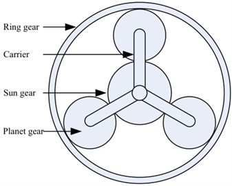
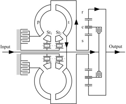
Fig. 2 shows the schematic of the PRHTS. A major characteristic of the PRHTS is the torque converter with the reflux power path, comprising the turbine that is connected to the input shaft of the transmission system and the pump that is connected to the sun gear of the planetary gear train. In addition, the torque converter has two stators, which is another unique characteristic of the PRHTS. An important characteristic of the double stator torque converter is the wide high efficiency range of more than 80 %, because the working condition consists of two converter conditions and a coupling condition. It can amplify the range of transmission ratio of the PRHTS in high efficiency range by using the double stator torque converter.
The power flow of the PRHTS is shown in Fig. 2 and is described as follows. First, the power of the engine enters the input shaft of the PRHTS (at the left side of Fig. 2). The power is then transferred into the carrier of the planetary gear train. Most of the power is transmitted into the ring gear (at the right side of Fig. 2), which is the power split characteristics of the planetary gear train. The remainder of the power, called reflux power, enters into the pump of the torque converter by the sun gear. Then, the reflux power goes into the input shaft of the PRHTS by torque amplification of the torque converter. The reflux power joins with the output power of engine, and both enter into the carrier. Because of the special reflux power characteristics, the PRHTS has a continuous variable ratio. In other words, the output shaft of the transmission system has a continuous variable speed by means of the torque converter, while the speed of the engine is constant. Therefore, the PRHTS is a CVT system.
Fig. 2Schematic and power flow of the PRHTS
2.2. The basic characteristics of the PRHTS
2.2.1. The speed ratio characteristic of the PRHTS
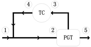
The simplified power flow of the PRHTS is shown in Fig. 3.
Fig. 3Simplified power flow of the PRHTS: 1 – input power of the system; 2 – input power of the carrier; 3– input power of the torque converter; 4 – output power of the torque converter; 5 – output power of the system. The arrows represent the direction of power flow
The rotational speed equation of the planetary gear train is as follows:
It is assumed that the direction of the rotational speed of the input shaft is the positive direction.
The main speed ratio relationships of the PRHTS are given in following equations:
Using Eqs. (1-7), it is obtained that the relationship between and , as follows:
In the above formula, it is obvious that the PRHTS speed ratio increases with the torque converter speed ratio, but it is not a linear function. Thus, the PRHTS speed ratio is high when the torque converter speed ratio is at high efficiency range.
2.2.2. Efficiency characteristic of the two-degree-of-freedom planetary gear train
The planetary gear train is considered as an important component of the PRHTS because its efficiency affects the PRHTS; therefore, a mechanical efficiency analysis is a required step to design the PRHTS. The planetary gear train is commonly used in the reducer by locking one component: the sun gear, ring gear, or carrier. In this case, the planetary gear train has one degree of freedom. However, the planetary gear train of the PRHTS has two degrees of freedom. Thus, its efficiency analysis is more complicated, and it has its own characteristics compared to the one-degree-of-freedom planetary gear train. The efficiency of the two-degree-of-freedom planetary gear train is determined by several factors such as the number of gears, type of planetary gear train, type of bearings, etc. Some researchers reported formulas of efficiency analysis for the two-degree-of-freedom planetary gear trains [28].
In this study, the efficiency of the two-degree-of-freedom planetary gear train will be analyzed by the methodology in the said researches.
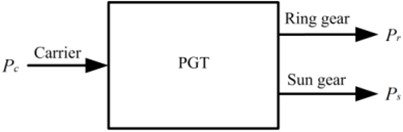
The power flow of the planetary gear train in the PRHTS is shown in Fig. 4. In the figure, denotes the power, while denotes the torque.
The rotational speed equation of the planetary gear train in Eq. (1) can be transformed as follows:
For the two-degree-of-freedom planetary gear train, the mechanical efficiency is:
Fig. 4Power flow of the planetary gear train in the PRHTS
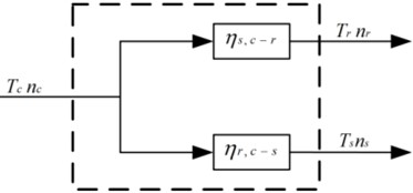
For the two-degree-of-freedom planetary gear train, the power flow formula is:
Using Eqs. (4-6), the mechanical efficiency of planetary gear train in the PRHTS is obtained:
According to Eq. (12), the mechanical efficiency of planetary gear train is not only dependent on the rotational speed of the sun gear, ring gear, and carrier, but also on the mechanical efficiency of the one-degree-of-freedom planetary gear train when the ring gear or sun gear is fixed. Therefore, it is necessary to calculate and . According to research [19], and is the function of which is the mechanical efficiency of the one degree of freedom planetary gear train when the carrier is held fixed. The formulas are as follows:
Considering calculation simplicity and operation practicability, is assumed to be constant, which is 0.985.
2.2.3. Efficiency characteristic of the two-degree-of-freedom planetary gear train
For the PRHTS, the torque characteristics equation of the planetary gear train is:
It is assumed that the direction of the torque acting on the planetary gear train is the positive direction. Then, the relationships among the torque in the PRHTS are obtained according to the transmission relationships of the system, as follows:
Paying special attention to the direction of the torque, we can see that and are equal and opposite in the hydraulic transmission system with reflux power, therefore, . Similarly, and are equal and opposite, therefore, .
Using Eqs. (15-20), the relationship between and is obtained as:
In order to get a better understanding of the PRHTS, the relationship between the torque ratio of the PRHTS and speed ratio of the PRHTS should be obtained. Using Eqs. (8) and (21), the relationship between and is obtained as follows:
Again, using Eqs. (8) and (21), the relationship between and is obtained as:
Using Eqs. (8) and (23), the relationship between and is:
2.2.4. Efficiency characteristic of the two-degree-of-freedom planetary gear train
In the PRHTS, the variator element is the torque converter, which has two stators. Fig. 5 shows the efficiency characteristics of the double stator torque converter [24]. It can be seen that the double stator torque converter maintains high efficiency over a wide range of speed ratios, which can amplify the transmission ratio range of the PRHTS in the high efficiency range. Using Eq. (22) and the efficiency characteristics of the torque converter, the torque ratio characteristics of the PRHTS are obtained (shown in Fig. 6). In the same way, the efficiency characteristics of the PRHTS can be obtained (shown in Fig. 7).
Fig. 5The efficiency characteristics of the double stator torque converter
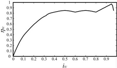
Fig. 6The torque ratio characteristics of the PRHTS
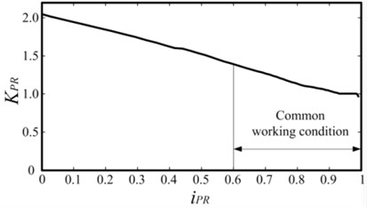
Fig. 7The efficiency characteristics of the PRHTS
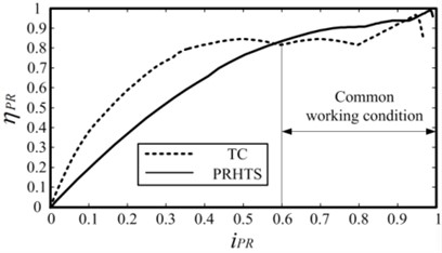
As observed in Fig. 7, the efficiency of the PRHTS is less than the torque converter at low speed ratio, but it is higher in the common working condition. Therefore, the efficiency of the PRHTS is higher than the torque converter in most working conditions of construction vehicles. Subsequently, construction vehicles coupled with PRHTS will have an improved fuel economy.
3. Wheel loader simulation
3.1. Wheel loader simulation
In the past decade, dynamic simulation has become an important part in vehicle design and development stages. A new technology can be examined without expensive measurements and with reduced time by simulation. In order to quantitatively study the effect of using the PRHTS on improving the fuel economy of construction vehicles, a wheel loader coupled with PRHTS is modeled and a numerical simulation is conducted under the wheel loader driving condition.
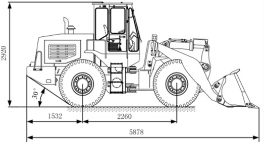
A wheel loader is a type of construction machinery characterized by quick and accurate movements. Wheel loaders are widely used in infrastructure construction such as transportation, water conservation, and electric power projects. Wheel loaders are used mainly for uploading materials into trucks, pipe laying, clearing rubble, and digging. In construction areas, they are also used to transport building materials (such as bricks, pipe, metal bars, and digging tools) over short distances. Wheel loaders are also used for snow removal, using their bucket as a snow basket but usually by using a snow plow attachment. They clear snow from streets, highways, and parking lots. They sometimes load snow into dump trucks for transport. The overall structure of a wheel loader is shown in Fig. 8. The wheel loader is used as the reference vehicle for the simulation work. Fig. 8 and Table 1 show the wheel loader dimensions and main characteristics. It can be seen that the rated power of internal combustion engine is 58 kW. In addition, the wheel loader has two forward gears; the forward gear Ⅱ is used to travel between work sites.
Table 1Main characteristics of the wheel loader
Symbol | Quantity | Value |
Length × Width × Height | 5878×2140×2920 mm | |
Wheelbase | 2260 mm | |
Rated power | 58 kW | |
Engine displacement | 4214 ml | |
Rated load | 2000 kg | |
Bucket capacity | 1.2 m3 | |
Wheel rolling radius | 0.53 m | |
Vehicle mass | 6480 kg | |
Maximum tractive force | 56 kN | |
Frontal area | 3.5 m2 | |
Air resistance coefficient | 0.3 | |
Speed ratio of forward gear I | 2.5 | |
Speed ratio of forward gear Ⅱ | 1.2 | |
Speed ratio of final drive | 8.3 |
Fig. 8Wheel loader dimensions
3.2. Transmission layout
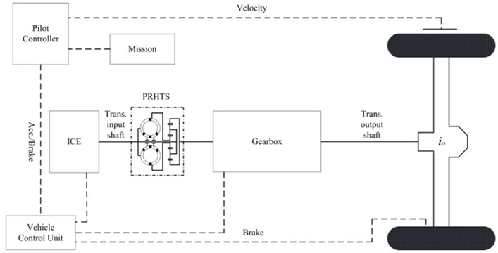
The layout of PRHTS for the wheel loader is shown in Fig. 9. In the figure, the dash-dot lines are used to highlight the PRHTS, while the dashed lines are used to indicate the main sensor and command signals.
Fig. 9Layout of PRHTS for the wheel loader
3.3. Transmission modeling of the wheel loader
The mechanical transmission and PRHTS of the wheel loader, as well as the whole control system, are modeled and simulated using LMS Imagin.Lab AMESim commercial software. The transmission modeling of the wheel loader is synthetically described as follows. The pilot controller unit exports the acceleration/brake signal on the basis of the wheel loader velocity and driving condition. The engine control unit exports the engine control signal on the basis of the engine rotational speed and acceleration/brake signal. The transmission control unit exports shift signal on the basis of the wheel loader velocity, acceleration/brake signal, and engine rotational speed. The driving axle will brake on the basis of the brake signal. In order to obtain a better comparison, the same control strategy is used for the original wheel loader and the wheel loader coupled with PRHTS.
Fig. 10Engine map
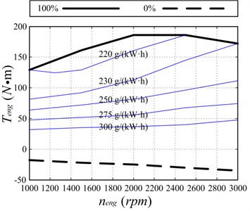
The engine, which is the most important element, is modeled on the basis of the engine map from steady-state experiments. In addition, the engine torque is a function of the accelerator position and the rotational speed in the transmission modeling of the wheel loader. The fuel consumption is calculated on the basis of the load and rotational speed of the engine. The engine map is described in Fig. 10. It can be seen that the minimum fuel consumption rate is 220 g/(kW·h), and the maximum engine torque is obtained between 2000 rpm and 2500 rpm.
3.4. Driving condition of the wheel loader
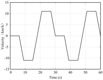
In this study, the driving condition of the wheel loader consists of two parts [21]. The first part is the low speed work cycle, which is shown in Fig. 11. The low speed cycle is a simulation when the wheel loader travels between a dirt pile loading point and a dump truck unloading point. The maximum wheel loader velocity is 11 km/h. A complete cycle will take approximately 60 s and is repeated 20 times in the driving condition.
Fig. 11Wheel loader driving condition in the first part
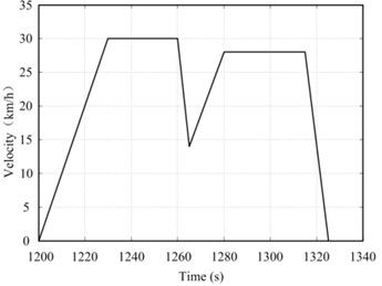
The second part of the driving condition is the high speed part, which is shown in Fig. 12. The high speed part is a simulation when the wheel loader travels between work sites, and it is the end of the driving condition of the wheel loader. It can be seen that the maximum wheel loader velocity is 30 km/h in Fig. 12. The second part will last 123 s, and the approximate distance traveled is 1 km.
Fig. 12Wheel loader driving condition in the second part
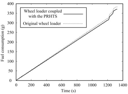
In order to quantitatively compare the fuel consumption of the original wheel loader and the wheel loader coupled with PRHTS, both wheel loaders have been simulated using the mentioned driving conditions. The fuel consumption simulation results of the two wheel loaders are shown in Fig. 13. The solid line represents the fuel consumption of the wheel loader coupled with PRHTS, while the dashed line represents the fuel consumption of the original wheel loader. It can be seen that the fuel consumption of the wheel loader is reduced by 3.39 % using PRHTS. Therefore, the PRHTS is an effective solution to reduce the fuel consumption and emission from construction vehicles.
Fig. 13The fuel consumption of the original wheel loader and the wheel loader coupled with PRHTS
4. Conclusions
1) The PRHTS-a new CVT system-is proposed to improve the efficiency of the torque converter in construction vehicles. The basic characteristics of the PRHTS such as the speed ratio, efficiency, and torque are analyzed by expounding its basic structure and operational principle. The basic characteristics are then obtained by numerical calculation.
2) The mechanical transmission and the PRHTS of the wheel loader, as well as the whole control system, are modeled and simulated using LMS Imagin.Lab AMESim commercial software. In order to obtain a better comparison, the same control strategy is used for the original wheel loader and the wheel loader coupled with PRHTS. The control system is based on the acceleration/brake signal, engine rotational speed signal, and wheel loader velocity signal.
3) The fuel consumptions of the wheel loader equipped with two different transmission systems, namely, the traditional torque converter and PRHTS are compared under the driving condition. The simulation results show that the fuel consumption of the wheel loader coupled with PRHTS is reduced by 3.39 %, compared with that of the original wheel loader. Therefore, the wheel loader coupled with PRHTS can effectively enhance transmission efficiency and fuel economy.
References
-
C. Li, F. Meng, J. Xi, and Y. Zhai, “Starting shift control of heavy-duty automatic transmissions based on the optimal trajectory of turbine speed,” Mechanical Systems and Signal Processing, Vol. 126, pp. 490–504, Jul. 2019, https://doi.org/10.1016/j.ymssp.2019.02.030
-
Z. Zhao, J. Chen, X. Li, and D. Lei, “Downshift decision and process optimal control of dual clutch transmission for hybrid electric vehicles under rapid braking condition,” Mechanical Systems and Signal Processing, Vol. 116, pp. 943–962, Feb. 2019, https://doi.org/10.1016/j.ymssp.2018.07.012
-
S. M. Park, T. W. Park, S. H. Lee, S. W. Han, and S. K. Kwon, “Analytical study to estimate the performance of the Power Shift Drive (PSD) Axle for a forklift,” International Journal of Automotive Technology, Vol. 11, No. 1, pp. 49–56, Feb. 2010, https://doi.org/10.1007/s12239-010-0007-3
-
F. Meng, G. Tao, and H. Chen, “Smooth shift control of an automatic transmission for heavy-duty vehicles,” Neurocomputing, Vol. 159, pp. 197–206, Jul. 2015, https://doi.org/10.1016/j.neucom.2015.02.004
-
H. Chen and X. Chen, “A new methodology for multistage multispeed planetary transmission design based on geometry,” Journal of Mechanical Design, Vol. 143, No. 11, p. 143, Nov. 2021, https://doi.org/10.1115/1.4050745
-
Z. Li and J. Sandhu, “Transmission torque converter arc spring damper dynamic characteristics for driveline torsional vibration evaluation,” SAE International Journal of Passenger Cars – Mechanical Systems, Vol. 6, No. 1, pp. 477–482, Apr. 2013, https://doi.org/10.4271/2013-01-1483
-
X. Liu and D. Sun, “An improved design of power-cycling hydrodynamic mechanical transmission,” Journal of Mechanical Science and Technology, Vol. 34, No. 8, pp. 3165–3179, Aug. 2020, https://doi.org/10.1007/s12206-020-0708-0
-
D. Robinette, M. Grimmer, and R. Beikmann, “Dynamic torque characteristics of the hydrodynamic torque converter,” in SAE International Journal of Passenger Cars – Mechanical Systems, Vol. 4, No. 2, pp. 1023–1032, May 2011.
-
I. Arango and S. Muñoz Alzate, “Numerical design method for CVT supported in standard variable speed rubber V-belts,” Applied Sciences, Vol. 10, No. 18, p. 6238, Sep. 2020, https://doi.org/10.3390/app10186238
-
K. Çağatay Bayindir et al., “A comprehensive overview of hybrid electric vehicle: Powertrain configurations, powertrain control techniques and electronic control units,” Energy Conversion and Management, Vol. 52, No. 2, pp. 1305–1313, Feb. 2011, https://doi.org/10.1016/j.enconman.2010.09.028
-
H.-S. Yan and L.-C. Hsieh, “Maximum mechanical efficiency of infinitely variable transmissions,” Mechanism and Machine Theory, Vol. 29, No. 5, pp. 777–784, Jul. 1994, https://doi.org/10.1016/0094-114x(94)90120-1
-
G. Mantriota, “Power split continuously variable transmission systems with high efficiency,” Proceedings of the Institution of Mechanical Engineers, Part D: Journal of Automobile Engineering, Vol. 215, No. 3, pp. 357–358, Mar. 2001, https://doi.org/10.1243/0954407011525692
-
S. S. Volpe, G. Carbone, M. Napolitano, and E. Sedoni, “Design optimization of input and output coupled power split infinitely variable transmissions,” Journal of Mechanical Design, Vol. 131, No. 11, p. 11100, Nov. 2009, https://doi.org/10.1115/1.3179145
-
P. Linares, V. Méndez, and H. Catalán, “Design parameters for continuously variable power-split transmissions using planetaries with 3 active shafts,” Journal of Terramechanics, Vol. 47, No. 5, pp. 323–335, Oct. 2010, https://doi.org/10.1016/j.jterra.2010.04.004
-
F. Bottiglione and G. Mantriota, “Effect of the ratio spread of CVU in automotive kinetic energy recovery systems,” Journal of Mechanical Design, Vol. 135, No. 6, p. 06100, Jun. 2013, https://doi.org/10.1115/1.4024121
-
J. R. Gomà Ayats, J. Vivancos Calvet, J. Minguella Canela, U. Diego-Ayala, and F. Fenollosa Artes, “Power transmitted through a particular branch in mechanisms comprising planetary gear trains and other fixed or variable transmissions,” Mechanism and Machine Theory, Vol. 46, No. 11, pp. 1744–1754, Nov. 2011, https://doi.org/10.1016/j.mechmachtheory.2011.06.005
-
A. Dhand and K. Pullen, “Analysis of continuously variable transmission for flywheel energy storage systems in vehicular application,” Proceedings of the Institution of Mechanical Engineers, Part C: Journal of Mechanical Engineering Science, Vol. 229, No. 2, pp. 273–290, Feb. 2015, https://doi.org/10.1177/0954406214533096
-
M. Delkhosh and M. Saadat Foumani, “Introduction and optimization of a power split continuously variable transmission including several fixed ratio mechanisms,” Scientia Iranica, Vol. 22, No. 1, pp. 226–234, Feb. 2015.
-
S. M. Savaresi, F. L. Taroni, F. Previdi, and S. Bittanti, “Control system design on a power-split CVT for high-power agricultural tractors,” IEEE/ASME Transactions on Mechatronics, Vol. 9, No. 3, pp. 569–579, Sep. 2004, https://doi.org/10.1109/tmech.2004.835334
-
B. Carl, M. Ivantysynova, and K. Williams, “Comparison of operational characteristics in power split continuously variable transmissions,” in SAE 2006 Commercial Vehicle Engineering Congress and Exhibition, Oct. 2006, https://doi.org/10.4271/2006-01-3468
-
R. Kumar, M. Ivantysynova, and K. Williams, “Study of energetic characteristics in power split drives for on highway trucks and wheel loaders,” in SAE 2007 Commercial Vehicle Engineering Congress and Exhibition, Oct. 2007, https://doi.org/10.4271/2007-01-4193
-
R. Kumar and M. Ivantysynova, “An instantaneous optimization based power management strategy to reduce fuel consumption in hydraulic hybrids,” International Journal of Fluid Power, Vol. 12, No. 2, pp. 15–25, Jan. 2011, https://doi.org/10.1080/14399776.2011.10781027
-
K. Pettersson and P. Krus, “Design optimization of complex hydromechanical transmissions,” Journal of Mechanical Design, Vol. 135, No. 9, Sep. 2013, https://doi.org/10.1115/1.4024732
-
H. Wang, D. Y. Sun, and D. T. Qin, “A new continuously variable transmission system applied to transmission system of the roadheader’s cutting unit,” Proceedings of the Institution of Mechanical Engineers Part C-Journal of Mechanical Engineering Science, Vol. 231, No. 19, pp. 3590–3600, 2017, https://doi.org/10.1177/095440621664940
-
H. Wang and D. Sun, “Theory and application on power-cycling variable transmission system,” Journal of Mechanical Design, Vol. 139, No. 2, Feb. 2017, https://doi.org/10.1115/1.4035055
-
Y. You, D. Sun, and D. Qin, “Shift strategy of a new continuously variable transmission based wheel loader,” Mechanism and Machine Theory, Vol. 130, pp. 313–329, Dec. 2018, https://doi.org/10.1016/j.mechmachtheory.2018.08.004
-
B. Li, D. Sun, M. Hu, and J. Liu, “Automatic starting control of tractor with a novel power-shift transmission,” Mechanism and Machine Theory, Vol. 131, pp. 75–91, Jan. 2019, https://doi.org/10.1016/j.mechmachtheory.2018.09.012
-
E. Pennestri` and F. Freudenstein, “The mechanical efficiency of epicyclic gear trains,” Journal of Mechanical Design, Vol. 115, No. 3, pp. 645–651, Sep. 1993, https://doi.org/10.1115/1.2919239
-
G. Mantriota, “Theoretical and experimental efficiency analysis of multi-degrees-of-freedom epicyclic gear trains,” Multibody System Dynamics, Vol. 9, No. 4, pp. 389–408, 2003, https://doi.org/10.1023/a:1023319515306
-
E. Pennestrı` and P. P. Valentini, “A review of formulas for the mechanical efficiency analysis of two degrees-of-freedom epicyclic gear trains,” Journal of Mechanical Design, Vol. 125, No. 3, pp. 602–608, Sep. 2003, https://doi.org/10.1115/1.1587157
-
E. Pennestrì, L. Mariti, P. P. Valentini, and V. H. Mucino, “Efficiency evaluation of gearboxes for parallel hybrid vehicles: Theory and applications,” Mechanism and Machine Theory, Vol. 49, pp. 157–176, Mar. 2012, https://doi.org/10.1016/j.mechmachtheory.2011.10.012
About this article

The authors would like to acknowledge the support and contribution from the Key Laboratory of Advanced Manufacturing Technology for Automobile Parts, Chongqing University of Technology, China. The study was funded by the National Natural Science Foundation of China (Grant No. 52005067 and No. 52172355), Natural Science Foundation Project of Chongqing Science and Technology Commission (cstc2021jcyj-msxmX0555), The Cultivation Plan for the Research and Innovation Team of Chongqing University of Technology (2023TDZ011), Youth Project of Science and Technology Research Program of Chongqing Education Commission of China (No. KJQN202201159).
The datasets generated during and/or analyzed during the current study are available from the corresponding author on reasonable request.
The authors declare that they have no conflict of interest.
