Abstract
Embedded turnout is one of the key facilities in the embedded track network of modern tram systems. In this study, the damping performance and track stiffness of an embedded turnout are tested on site. A multi-rigid body dynamics model of the tram and a finite-element dynamics model of the embedded turnout are established, and the two models are coupled based on the wheel-rail contact theory for the turnout area. Next, the dynamic responses of the tram passing through the embedded turnout are analyzed. The results show that the embedded turnout has favorable damping performance. The high stiffness of variable section rails at the switch and frog would lead to an increase in the wheel-rail dynamic force. When the tram passes through the embedded turnout, the wheel-rail vertical force reaches maximum values of 106.3 and 35.2 kN at the frog and switch, respectively; the maximum wheel derailment coefficient and wheel weight reduction rate are 0.49 and 0.57, respectively, which are within the safety limit specified in the Standards; the maximum lateral and vertical vibration accelerations of the tram body are 0.38 and 0.71 m/s2, respectively, satisfying the comfort requirements; the wheel–rail wear work at the switch is greater than that at the frog.
Highlights
- The embedded turnout demonstrated favorable damping performance, which helps to reduce the vibration of tram-rail system.
- The track stiffness was relatively high on the variable section rails, which increased the wheel-rail dynamic force of the passing tram.
- When the tram passed through the embedded turnout, the maximum values of wheel-rail vertical and lateral force were 106.3 and 35.2 kN at the frog and switch, respectively.
- When the tram passed through the embedded turnout, the maximum wheel derailment coefficient and wheel weight reduction rate increased to 0.49 and 0.57, respectively, which did not exceed the safety limit specified in the Standard.
- When the tram passed through the branch line of the embedded turnout, the maximum vertical and lateral vibration accelerations of the tram body were 0.38 and 0.71 m/s2, respectively, both of which satisfied the comfort indices.
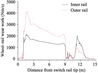
- The wheel-rail wear work at the switch was larger than that at the frog. On the both rail of the branch line, the maximum wheel-rail wear work recorded at the switch and frog were 4,180.3 and 2,105.4 Nm/s, respectively.
1. Introduction
Embedded track is a new type of rail system that embeds the rails into the troughs of track slabs and uses polymers to support and lock the rails [1]. Compared with conventional tracks, embedded tracks offer limited vibration and low noise [2], and have thus been extensively applied in modern trams, light rail, and other forms of urban rail transit system. When a railway vehicle passes through, the dynamic performance on embedded tracks differs significantly from that on conventional tracks. Hence, Han et al. [3, 4] examined the dynamic performance of metro trains passing through embedded tracks and compared it with the dynamic response of ordinary tracks. Yang et al. [5] adopted experimental and numerical methods to analyze the wheel-rail impact at insulated rail joints used in embedded track system, and found the major frequencies of the impact vibration depend mainly on geometric irregularities and train speed. Elkamel et al. [6] established a finite element model of embedded track structure in the mixed traffic area, and calculated the deformation and stress of asphalt surface course and filling material. Hu et al. [7] performed a comparative analysis on the dynamic performance indices of vehicles in an embedded track system and those in a typical fastener type track system. Zou et al. [8] established a dynamic model for embedded tracks under moving loads and investigated the effects of moving load speed, rail type, and support stiffness. Braghin [9] proposed an integrated approach for the design of embedded track system, including finite element analysis, lab tests and time-domain numerical simulation of train-track dynamic interaction. These studies mainly focused on the loading state, stiffness design, and vibration reduction performance of embedded tracks through on-site testing and numerical simulation, and has made progress in the safety and reliability evaluation of embedded track structures.
Turnout serves as the key equipment of railway that enables a train to switch from one track line to another [10]. Embedded turnout is a new form of turnout widely adopted in modern tram systems, and there is currently few research on it. Wei et al. [11] conducted a finite-element analysis pertaining to the seamlessness of embedded turnouts. Fu [12] optimized an embedded turnout gap detection system. Huang et al. [13] developed an embedded whole-cast crossing nose, which can adapt to the operational requirements of heavy-haul railway. Zhao et al. [14] established a tram-turnout coupling dynamics model by multi-body dynamics software systematically, and analyzed the dynamic performance of tram passing small-number turnout in reverse direction under different wheel diameter differences and amplitudes. Owing to the complex structure of turnouts, the wheel-rail dynamic interactions become intense when a vehicle passes through the turnout area, which would damage the tracks and threaten operational safety [15]. However, based on the review of existing literature, there is still a lack of research on the dynamics of tram-embedded turnout coupling system, making it difficult to obtain the dynamic performance of trams when passing through embedded turnout. Therefore, it is necessary to establish a dynamic analysis method for tram-turnout coupling system in embedded turnout area, to provide a theoretical basis for the design, operation, and maintenance of embedded turnout.
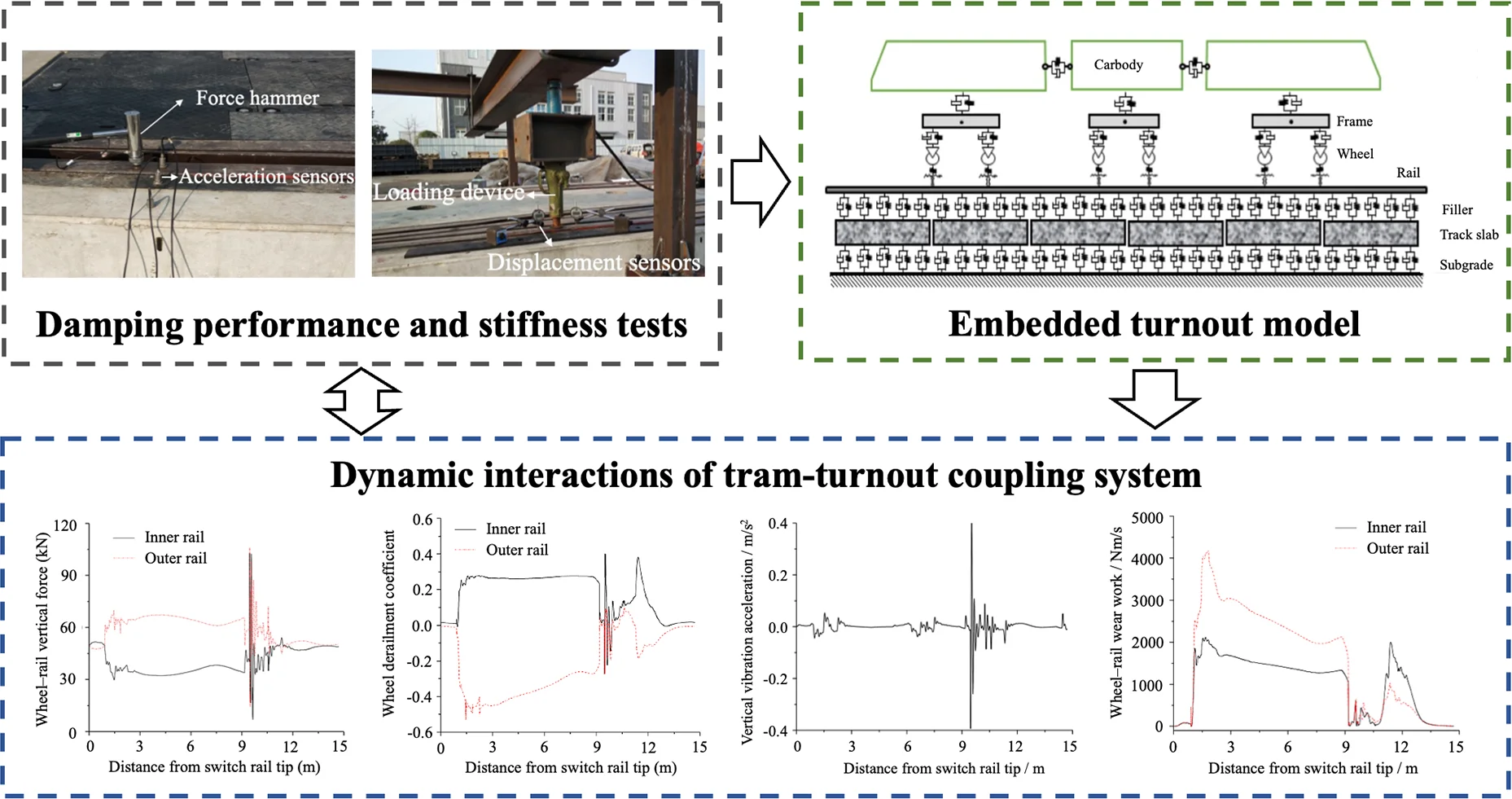
For this study, the embedded turnout structure of trams is first introduced herein. Field tests are performed to investigate the damping performance and stiffness of the embedded turnout. Then, a multi-rigid body dynamics model of the tram and a finite-element dynamics model of the embedded turnout are established. Based on the wheel-rail normal and tangential contact models in the turnout area, the abovementioned two models are coupled into the dynamics model of the coupling system between the tram and embedded turnout. The dynamics model is used to analyze the dynamic interactions between the tram and embedded turnout, primarily including four aspects: wheel-rail force, safety, smoothness, and wheel-rail wear.
2. Embedded turnout structure for trams
In the embedded turnout area of trams, the track gauge is 1,435 mm and the turnout length is 16.924 mm, where the projection distance between the beginning of turnout and the centre of turnout on the reference line is 4.758 m, and the projection distance between the centre of turnout and the end of turnout on the reference line is 12.166 m. The lead curve is a single circular curve with a radius of 50 m. The switch rails are horizontal tip-concealed semi-tangent lines, with the tangent point at the section with a top width of 29.75 mm.
Fig. 1General structure of embedded turnout of trams
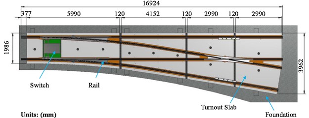
Fig. 1 shows the general structure of an embedded turnout of trams. The one-piece switch presents an integral alloy steel structure, where ordinary steel rails are welded to the front and rear of the alloy steel. It is composed of an alloy steel switch rail seat, switch rails, and factory-welded rails. The switch rails can be replaced separately. The frog is welded using NM400 and Q345 steel plates, with ordinary steel rails welded to its front and rear, thus obviating the necessity for welding between different materials on site. The guard rails, which feature a combined structure, are connected to the closure rails via the supporting seat, and can be adjusted or replaced easily.
3. Damping performance and stiffness tests of embedded turnout
Track stiffness and damping contributes significantly to the dynamic behaviors of vehicles passing through embedded turnouts. To evaluate the dynamic performance of the embedded turnout, on-site tests were conducted on the damping performance and track stiffness of the embedded turnout. And the test results were used to determine the parameters for the dynamics simulation of the coupling system between the tram and embedded turnout in Section 4.
3.1. Damping performance test of embedded turnout
Based on the structural features of an embedded turnout system, the measuring points were arranged at the switch rails, frog, rail welds, guard rails, and stock rails. From top to bottom, acceleration sensors were installed at the rail surface, polymer, and track slab in the cross-section of each measuring point. Subsequently, the vibration features of the embedded turnout were tested at Chengdu Xinzhu Transportation Technology Co., Ltd. in Sichuan Province in April 2017, as shown in Fig. 2.
Fig. 2Layout of measuring points for vibration damping performance test and on-site testing photo
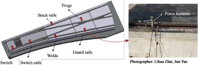
The frequency response function of the rails was obtained by collecting the hammer excitation signals of the embedded turnout system. On this basis, the structural damping ratio at the first order vibration frequency of the rails relative to the track structure could be identified. Along the longitudinal direction, the rails were hammered at positions near the acceleration sensors to obtain the vibration acceleration level of the rails and track slabs. The results are shown in Table 1, showing a favorable damping performance of the embedded turnout system.
Table 1Test results of damping performance of embedded turnout
Serial number | Cross-section | Total vibration acceleration level of rails (dB) | Total vibration acceleration level of track slabs (dB) | Transmission loss (dB) |
1 | Switch | 125.78 | 91.83 | 33.95 |
2 | Switch rails | 126.62 | 90.32 | 36.30 |
3 | Welds | 128.24 | 94.65 | 33.59 |
4 | Guard rails | 131.67 | 94.21 | 37.46 |
5 | Frog | 117.01 | 90.53 | 26.48 |
6 | Stock rails | 127.60 | 93.50 | 34.10 |
Mean | 126.15 | 92.51 | 33.64 | |
3.2. Stiffness test of embedded turnout
The track stiffness of the embedded turnout was measured by recording the force and displacement during vertical loading as well as fitting the relationships using the relevant software. The test was conducted at Chengdu Xinzhu Transportation Technology Co., Ltd. in Sichuan Province in April 2017. 28 measuring points were arranged at the cross-section of switch rails, frog, guard rails, and welds, as shown in Fig. 3. The results were used for the dynamic simulation in Section 4.
Fig. 3Layout of measuring points for track stiffness test and on-site testing photo
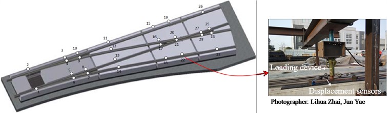
Table 2 shows the results of track stiffness measured at the 28 points of the embedded turnout. The track stiffness was relatively high at the measuring points on the variable section rails, such as the switch rails and nose rails (e.g., points 5, 20, and 28), owing to the guard rail effect arising from the combination of multiple rails. This abrupt increase in stiffness may exacerbate the dynamic forces between the wheels and rails when the tram passes through the turnout.
Table 2Test results of track stiffness of embedded turnout
Measuring point | Stiffness (kN/mm) | Measuring point | Stiffness (kN/mm) | Measuring point | Stiffness (kN/mm) | Measuring point | Stiffness (kN/mm) |
1 | 76.47 | 8 | 136.77 | 15 | 78.58 | 22 | 69.89 |
2 | 69.85 | 9 | 124.14 | 16 | 86.75 | 23 | 86.23 |
3 | 88.01 | 10 | 76.50 | 17 | 93.52 | 24 | 102.80 |
4 | 180.2 | 11 | 91.91 | 18 | 88.06 | 25 | 108.95 |
5 | 153.77 | 12 | 85.31 | 19 | 70.79 | 26 | 86.20 |
6 | 101.97 | 13 | 95.69 | 20 | 111.14 | 27 | 122.06 |
7 | 77.75 | 14 | 91.71 | 21 | 110.6 | 28 | 125.94 |
4. Dynamics model of tram-embedded turnout coupling system
In this paper, a dynamics model of tram-embedded turnout coupling system was established. At first, a tram sub-model and an embedded turnout sub-model were constructed, respectively. And then, they were coupled through the wheel-rail contact theory. Explicit linear dynamics solution method was adopted to analyze the dynamic interaction between the tram and the embedded turnout, and MATLAB language was used for computer compilation.
4.1. Tram model
Based on multibody dynamics theory, a full vehicle dynamics simulation model for a 100 % low-floor tram was established. It was comprised of a power bogie, independent wheels, and an inter-body hinged structure, as shown in Fig. 4. The tram model featured 118 degrees of freedom, among which 16 were non-independent. More details about the tram model can be found in reference [16]. And the main parameters can be found in Table 3 in subsection 4.3.
4.2. Embedded turnout model
After comprehensively considering the structure of the embedded turnout in Fig. 1, a finite-element model was established for the embedded turnout of trams, as shown in Fig. 5.
Fig. 4Tram dynamics model
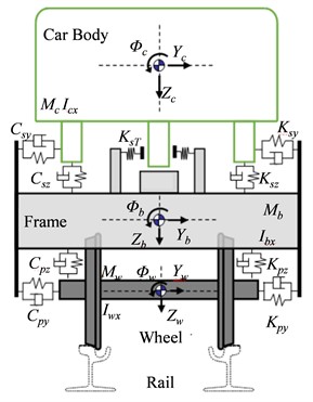
Fig. 5Embedded turnout dynamics model
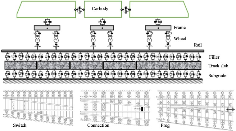
The model of embedded turnout was comprised of three components: the switch, connection, and frog, as can be seen in Fig. 5. The switch rails, nose rails, and wing rails were simplified as three-dimensional variable-section beam structures with continuous elastic support. The stock rails, closure rails, and guard rails were modelled as three-dimensional equal-section beam structures with continuous elastic support. The track slabs were modelled as three-dimensional variable-section slab structures with continuous elastic support. And the connection between the rails and track slabs, and that between the track slabs and roadbed were modelled as spring-damping structures [17, 18].
4.3. Wheel-rail contact models
The trace method [19] was employed to determine the wheel-rail geometric contact relationship between the tram and embedded turnout. The Hertz normal contact theory and creep-slip theory [20, 21] were adopted to analyze the normal and tangential interactions between the wheels and rails, and to establish the wheel-rail contact models of the vehicle passing through the embedded turnout [22]. Then, using the wheel-rail normal and tangential contact models in the turnout area, the multi-rigid body dynamics model of the tram and the finite-element dynamics model of the embedded turnout were coupled into the dynamics model of tram-turnout coupling system. This model would be used to analyze the dynamic interactions between the tram and embedded turnout, which enables the evaluations of operational safety and smoothness of trams.
The key parameters of the model were showed in Table 3.
Table 3The key parameters of the model
Parameter | Unit | Value | Parameter | Unit | Value |
Car body mass | kg | 11368 | Bogie mass | kg | 1583 |
Car body inertia | kg·m2 | 37815 | Bogie inertia | kg·m2 | 368 |
Wheel mass | kg | 933 | Wheel diameter | mm | 600 |
Train longitudinal connection stiffness | N/m | 5×10⁸ | Train longitudinal connection damping | N·s/m | 3000 |
Primary suspension stiffness | N/m | 4×10⁶ | Primary suspension damping | N·s/m | 2×10⁴ |
Secondary suspension stiffness | N/m | 2×10⁶ | Secondary suspension damping | N·s/m | 6×10⁴ |
60R2 Rail mass | kg/m | 59.75 | 60R2 rail bending stiffness | N·m2 | 6.9×10⁶ |
Elastic restraint support stiffness | N·m-1·m-1 | 1.1×10⁷ | Elastic restraint support damping | N·m-1·m-1 | 6.1×10⁴ |
Subgrade support stiffness | N·m-1·m-1 | 1.2×10⁸ | Subgrade support damping | N·m-1·m-1 | 7×10⁴ |
5. Dynamic interactions of tram-turnout coupling system
Based on the dynamics model presented in Section 4, the dynamic interactions of a tram-turnout coupling system passing through an embedded turnout in the reverse lateral direction were simulated at 20 km/h. And the wheel–rail forces, safety, smoothness, and wheel-rail wear was analyzed.
5.1. Wheel-rail force analysis
When the tram entered the branch line laterally, the vertical and lateral forces between the first wheelset and the tracks were extracted from the model, as shown in Fig. 6.
Fig. 6Results of wheel-rail force analysis of the tram passing through the embedded turnout
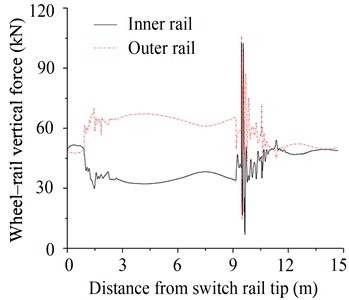
a) Wheel-rail vertical force
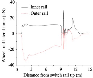
b) Wheel-rail lateral force
As can be seen in Fig. 6(a), the centrifugal force of the tram was not effectively offset because curve superelevation was not adopted in the branch line. Therefore, the outer rail born a greater vertical force compared to the inner rail. At the switch and frog, the maximum wheel-rail vertical force was significantly increased and reached 69.8 and 106.3 kN, respectively. This was mainly caused by three reasons. Firstly, when the tram passed through the switch and frog, there was a migration and fluctuation of the wheel-rail contact point. The second issue was owing to the abrupt change in track stiffness in this area, as indicated by the test in Section 3. And the third reason was attributed to the gap between the throat and nose rails, since the frog was fixed in the embedded turnout.
As shown in Fig. 6(b), when the tram entered the lead curve of the branch line laterally, the wheel-rail lateral force increased gradually. Meanwhile, the superposition of the contact unevenness at the switch caused the wheel-rail lateral force to a peak value at 35.2 kN. Since the frog was outside the range of the lead curve, the wheel-rail lateral force at the frog was relatively low, with a maximum value of only 19.0 kN.
5.2. Safety analysis
Due to the superposition of track irregularities and centrifugal forces, the lateral interaction between the tram and the embedded turnout would be significantly intensified, and the risk of train derailment by climbing the rails would be greatly increased. The wheel derailment coefficient and wheel weight reduction rate are important indicators reflecting the operational safety [23]. In this study, the vertical and lateral forces between the first wheelset and the tracks were extracted, and the wheel derailment coefficient and wheel weight reduction rate were computed when the tram passed through the embedded turnout, as can be seen in Fig. 7.
Fig. 7Safety analysis results of tram passing through embedded turnout
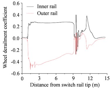
a) Wheel derailment coefficient
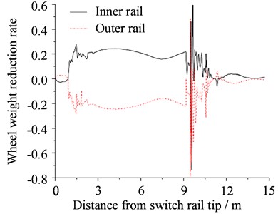
b) Wheel weight reduction rate
According to the European Standard UIC 518 and the Chinese Standard GB/T 5599-2019, the derailment coefficient should not exceed 0.8, and the wheel weight reduction rate should not exceed 0.65 [24]. As shown in Fig. 7(a), when the tram entered the branch line laterally, the variation law of the wheel derailment coefficient was similarly as the wheel-rail lateral force. The wheel derailment coefficient peaked at 0.49 and 0.24 at the switch and frog, respectively, within the safety limit of 0.8. Similarly, the wheel weight reduction rate peaked at 0.27 and 0.57 at the switch and frog, respectively, which were below the safety limit of 0.65. Thus, there is an increase in the risk of derailment at the switch and frog, but it is still within the safety requirements.
5.3. Smoothness analysis
Acceleration of car body is a key indicator of the running smoothness and riding comfort of vehicles [23]. Hence, we extracted the lateral and vertical vibration accelerations of the tram passing through the embedded turnout, as shown in Fig. 8. When the tram passed through the branch line of the embedded turnout, the vertical vibration acceleration of the body peaked at 0.05 and 0.38 m/s2 at the switch and frog, respectively. And the lateral vibration acceleration of the body peaked at 0.42 and 0.71 m/s2 at the switch and the frog, respectively. The high accelerations of the car body were due to the gap between the throat and nose rails in the frog. According to the European Standard UIC 518 and the Chinese Standard GB/T 5599-2019, to ensure the running smoothness, the lateral and vertical acceleration of the car body should be less than 2.5 m/s2 [24]. It can be seen that the values at both the switch and frog met the requirements.
Fig. 8Smoothness analysis results of tram passing through embedded turnout
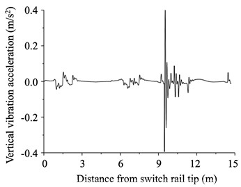
a) Vertical vibration acceleration
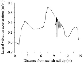
b) Lateral vibration acceleration
5.4. Wheel-rail wear analysis
When a tram passes through an embedded turnout, the wheels will lean against the gauge corner of the rail under the effect of centrifugal force, due to the absence of superelevation in the turnout area. This will result in severe side wear of the rails, and reduce the service life of the embedded turnout significantly. The wheel-rail wear work describes the wheel-rail wear when the tram reverses into the branch line of the embedded turnout, which can be derived from the wheel-rail creep force and wheel-rail creep rate [25]. In this study, we extracted the distribution law of the wheel-rail wear work from the dynamics model, as shown in Fig. 9. When the tram passed through the branch line of the embedded turnout, the distribution of wheel-rail wear work on the inner and outer rails of the branch line was almost the same. The wheel-rail wear work peaked at 4,180.3 and 2,105.4 Nm/s at the switch and frog, respectively. The wheel-rail wear work at the switch was larger than that at the frog.
Fig. 9Wheel-rail wear work of tram passing through embedded turnout
6. Conclusions
In this study, on-site tests were performed to investigate the damping performance and stiffness of an embedded turnout. Then, a multi-rigid body dynamics model of the tram and a finite-element dynamics model of the embedded turnout were established. Based on the wheel-rail contact theory in the turnout area, the abovementioned two models were coupled into the dynamics model of the tram-embedded turnout coupling system. The dynamics model was applied to analyze the dynamic interactions between the tram and embedded turnout. The main conclusions are as follows:
1) The embedded turnout demonstrated favorable damping performance, which helps to reduce the vibration of tram-rail system; the high stiffness of variable section rails at the switch and frog increased the wheel-rail dynamic force of the passing tram.
2) When the tram passed through the embedded turnout, the maximum values of wheel-rail vertical force were 106.3 and 35.2 kN at the frog and switch, respectively. The maximum wheel derailment coefficient and wheel weight reduction rate were 0.49 and 0.57, respectively, which did not exceed the safety limit specified in the Standard.
3) When the tram passed through the branch line of the embedded turnout, the maximum lateral and vertical vibration accelerations of the tram body were 0.38 and 0.71 m/s2, respectively, both of which satisfied the comfort indices.
4) The wheel-rail wear work at the switch was larger than that at the frog. On the outer rail of the branch line, the maximum wheel–rail wear work recorded at the switch and frog were 4,180.3 and 2,105.4 Nm/s, respectively.
The dynamic interaction analysis in this article helps to enhance the understanding of the tram-embedded turnout coupling system. However, there still exist the following limitations:
1) Though embedded turnouts have good vibration damping performance, it also means that durability issues may be more prone to occur, such as rail cracks, track slab cracks, and other damages. In the succeeding work, we will further conduct in-depth research on the long-term service performance of embedded turnout under the action of tram loads.
2) The dynamic simulation program was compiled in MATLAB language, and have not yet developed a visualization function module, so it cannot display an actual model interface. We will further develop the visualization function in further work.
References
-
Z. Zeng et al., “Numerical simulation research on mechanical optimization of a novel fastener type ballastless track (NFTBT) for tram,” Applied Sciences, Vol. 12, No. 17, p. 8807, Sep. 2022, https://doi.org/10.3390/app12178807
-
W. Sun, D. Thompson, M. Toward, and Z. Zeng, “Modelling of vibration and noise behaviour of embedded tram tracks using a wavenumber domain method,” Journal of Sound and Vibration, Vol. 481, p. 115446, Sep. 2020, https://doi.org/10.1016/j.jsv.2020.115446
-
J. Han, Y. He, J. Wang, and X. Xiao, “Simulation and experimental study on vibration and acoustic characteristics of a continuous supported embedded track,” Applied Acoustics, Vol. 180, p. 108103, Sep. 2021, https://doi.org/10.1016/j.apacoust.2021.108103
-
L. Ling, J. Han, X. Xiao, and X. Jin, “Dynamic behavior of an embedded rail track coupled with a tram vehicle,” Journal of Vibration and Control, Vol. 23, No. 14, pp. 2355–2372, Aug. 2017, https://doi.org/10.1177/1077546315616521
-
Z. Yang, P. Zhang, and L. Wang, “Wheel-rail impact at an insulated rail joint in an embedded rail system,” Engineering Structures, Vol. 246, p. 113026, Nov. 2021, https://doi.org/10.1016/j.engstruct.2021.113026
-
J. Bu and J. Li, “Numerical analysis of the embedded track structure under mixed traffic load,” MATEC Web of Conferences, Vol. 272, p. 01042, 2019, https://doi.org/10.1051/matecconf/201927201042
-
Y. D. Hu, G. Yang, R. T. Ma, and G. S. Liu, “Performance analysis of continuously supported embedded rail track system in urban rail transit,” (in Chinese), Urban Mass Transit, Vol. 23, No. 7, pp. 102–107, 2020, https://doi.org/10.16037/j.1007-869x.2020.07.021
-
J. H. Zou, W. X. Feng, and H. B. Jiang, “Dynamic response of an embedded railway track subjected to a moving load,” Journal of Vibroengineering, Vol. 13, No. 3, pp. 544–551, Sep. 2011.
-
F. Braghin, Collina A., and Corradi R., “An integrated approach for the dynamic performance estimation of an embeddedrail track system,” in International Conference on Structural Dynamics, pp. 828–833, 2011.
-
Y. Zhang, T. Xu, C. Chen, G. Wang, Z. Zhang, and T. Xiao, “A hierarchical method based on improved deep forest and case-based reasoning for railway turnout fault diagnosis,” Engineering Failure Analysis, Vol. 127, p. 105446, Sep. 2021, https://doi.org/10.1016/j.engfailanal.2021.105446
-
A. Q. Wei, P. Wang, J. L. Xiao, L. Wang, H. L. Jiao, and J. C. Wei, “Seamless analysis of No. 6 embedded turnout for tram,” (in Chinese), Journal of Railway Science and Engineering, Vol. 16, No. 1, pp. 57–64, 2019, https://doi.org/10.19713/j.cnki.43-1423/u.2019.01.008
-
X. Z. Fu, “Optimization of embedded point switch detection system,” Automation Research and Design Institute of Metallurgical Industry, Beijing, 2016.
-
Z. Y. Huang and W. Z. Fei, “The development of new heavy haul turnout,” (in Chinese), Railway Standard Design, Vol. 59, No. 1, pp. 42–46, 2015, https://doi.org/10.13238/j.issn.1004-2954.2015.01.0
-
S. Q. Zhao, J. M. Xu, Q. T. Ma, J. Y. Chen, and P. Wang, “Influence of wheel diameter difference on dynamic performance of tram cars passing through turnout,” (in Chinese), Journal of Railway Science and Engineering, Vol. 19, No. 8, pp. 2397–2406, 2022, https://doi.org/10.19713/j.cnki.43-1423/u.t20211040
-
E. Kassa, C. Andersson, and J. C. O. Nielsen, “Simulation of dynamic interaction between train and railway turnout,” Vehicle System Dynamics, Vol. 44, No. 3, pp. 247–258, 2006.
-
Y. Shan, X. Zhou, G. Cheng, Z. Jiang, and S. Zhou, “In-situ test on impact loads of a five-module 100% low-floor tram and the prediction of damage characteristics of a pile-plank-supported tram track,” Construction and Building Materials, Vol. 277, p. 122320, Mar. 2021, https://doi.org/10.1016/j.conbuildmat.2021.122320
-
J. W. Hu, J. Lee, and J. Seo, “Performance-based optimal design of self-centering friction damping brace systems between recentering capability and energy dissipation,” Journal of Mechanical Science and Technology, Vol. 28, No. 8, pp. 3129–3136, Aug. 2014, https://doi.org/10.1007/s12206-014-0721-2
-
J. Lai, J. Xu, T. Liao, Z. Zheng, R. Chen, and P. Wang, “Investigation on train dynamic derailment in railway turnouts caused by track failure,” Engineering Failure Analysis, Vol. 134, p. 106050, Apr. 2022, https://doi.org/10.1016/j.engfailanal.2022.106050
-
K. Y. Wang, W. M. Zhai, and C. B. Cai, “Effect of the wheel-rail profile and system parameters on the wheel-rail space contact geometry relation,” (in Chinese), Rolling Stock, Vol. 2, pp. 14–18, 2002.
-
P. Flores and J. Ambrósio, “On the contact detection for contact-impact analysis in multibody systems,” Multibody System Dynamics, Vol. 24, No. 1, pp. 103–122, Jun. 2010, https://doi.org/10.1007/s11044-010-9209-8
-
X. Ma, P. Wang, J. Xu, and R. Chen, “Comparison of non-Hertzian modeling approaches for wheel-rail rolling contact mechanics in the switch panel of a railway turnout,” Proceedings of the Institution of Mechanical Engineers, Part F: Journal of Rail and Rapid Transit, Vol. 233, No. 4, pp. 466–476, Apr. 2019, https://doi.org/10.1177/0954409718799825
-
Z.-P. Zeng, X.-D. Huang, J.-D. Wang, F.-S. Liu, W.-D. Wang, and A. A. Shuaibu, “Wheel-rail stochastic dynamics and rail wear analysis of small radius curved sections of a tram line based on generalized probability density evolution,” Proceedings of the Institution of Mechanical Engineers, Part F: Journal of Rail and Rapid Transit, Vol. 235, No. 5, pp. 543–558, May 2021, https://doi.org/10.1177/0954409720947533
-
W. Wang, Y. Zhang, and H. Ouyang, “Modeling uncertainties of vehicle-track coupled dynamic systems,” Mechanics Based Design of Structures and Machines, Vol. 49, No. 7, pp. 947–968, Oct. 2021, https://doi.org/10.1080/15397734.2019.1706557
-
H. L. Shi, R. Luo, and J. Zeng, “Review on domestic and foreign dynamics evaluation criteria of high-speed train,” (in Chinese), Journal of Traffic and Transportation Engineering, Vol. 21, No. 1, pp. 36–58, 2021, https://doi.org/10.19818/j.cnki.1671-1637.2021.01.002
-
C. G. Yu and G. Q. Tao, “Analysis of metro wheel wear based on field measurement and numerical simulation,” (in Chinese), Engineering Mechanics, Vol. 33, No. 1, pp. 201–208, 2016, https://doi.org/10.6052/j.issn.1000-4750.2014.06.0484
Cited by
About this article

The authors have not disclosed any funding.
The datasets generated during and/or analyzed during the current study are available from the corresponding author on reasonable request.
Conceptualization and methodology, Lihua Zhai; software and validation, Hongyu Wan; formal analysis, visualization and writing, Siqi Sun. All authors have read and agreed to the published version of the manuscript.
The authors declare that they have no conflict of interest.
