Abstract
In order to evaluate the influence of the dynamics parameters of the electric vehicles on the ride comfort, an electric vehicle dynamic model is established to simulate under various operation conditions of the electric vehicles. The electric vehicle dynamic equations and parameters are then solved based on the Simulink model built on Matlab software. The acceleration responses at centre of gravity of the vertical and pitching electric vehicle vibrations are two objective functions. The research results show that the ride comfort of electric vehicles is greatly influenced by their dynamics parameters and strongly reduced in comparison with the traditional vehicles. Therefore, the electric vehicles equipped with in-wheel motors should be optimized or controlled to improve the ride comfort.
Highlights
- An electric vehicle dynamic model is established to simulate under various operation conditions of the electric vehicles to evaluate the influence of the dynamics parameters of the electric vehicles on the ride comfort.
- The electric vehicle dynamic equations and parameters are then solved based on the Simulink model built on Matlab software.
- The research results show that the ride comfort of electric vehicles is greatly influenced by their dynamics parameters and strongly reduced in comparison with the traditional vehicles.
- Therefore, the electric vehicles equipped with in-wheel motors should be optimized or controlled to improve the ride comfort.
1. Introduction
In order to reduce environmental pollution and save energy, clean energies, such as biofuels and electric batteries, had been studied and used on engines or electric vehicles to decrease the use of the increasingly depleted fossil energy sources and environmental pollution [1, 2]. Especially, with the electric vehicles (EV), the electric batteries or fuel cells had been investigated and used on the EV as an energy source to replace engines in traditional vehicles (TV) equipped with internal combustion engines [3, 4]. However, the change of the dynamic parameters of the vehicles from the TV model to the EV model greatly affects the stability, ride comfort, and noise problem of the vehicles. Therefore, Jin L., et al. evaluate the effect of the mass ratio between sprung and unsprung on the vehicle's ride comfort driven by in-wheel motors (IWM) [5], Wang P., simulated and evaluated the effect of electric battery mass distribution on the EV movement safety [6]. To improve the electric vehicle ride comfort, the optimal control methods had been applied on the EV to control the suspension systems of the vehicle and IWM. Abdussalam A., et al. analyzed the influence of the mass of the IWM on the performance of passive and semi-active suspension systems of the EV [7]. Ma F., et al., and Liu M., et al., designed and optimized the in-wheel-motor electric vehicles to improve ride comfort by using three degrees of freedom of the EVs [8, 9]. Besides, Yu Y., et al. also analyzed the influence of rotor-bearing coupling vibration on the dynamic behavior of electric vehicle driven by an in-wheel motor [3]. The research results showed that the impact of the vertical force of in-wheel motors on the EV's vibration was very high. Thus, it significantly affected the EV’s ride comfort and moving safely.
To solve this problem, Liu M., et al., and Luo Y., et al. researched and added vibration isolation between the vehicle axle and the IWM [10, 11]. The vibration isolation of the IWM was then controlled by Tan D., et al. [12]. The study results showed that the ride comfort of the EV was significantly improved. The vehicle dynamics models of Nguyen V., et al. showed that the dynamic parameters of the vehicle systems as well as the suspension systems greatly affected the moving safe and ride comfort of the vehicles [13-15]. With the EVs, this issue has not yet been concerned in the existing studies. Therefore, the main goal of this research is to analyze the effect of the electric vehicle dynamics parameters on vehicle ride comfort. To solve the study aim, a dynamic model of the EV is established to simulate the results under the different excitations of the in-wheel motors and road surface roughness. Matlab/Simulink software is applied to solve the EV dynamic equations. The root-mean-square (RMS) acceleration responses of the vertical and pitching vibrations of the EV are selected as the objective studies. The research results are then compared with the results of the traditional vehicles to evaluate the EV ride comfort.
2. Materials and methods
2.1. Model of the electric-vehicle dynamics
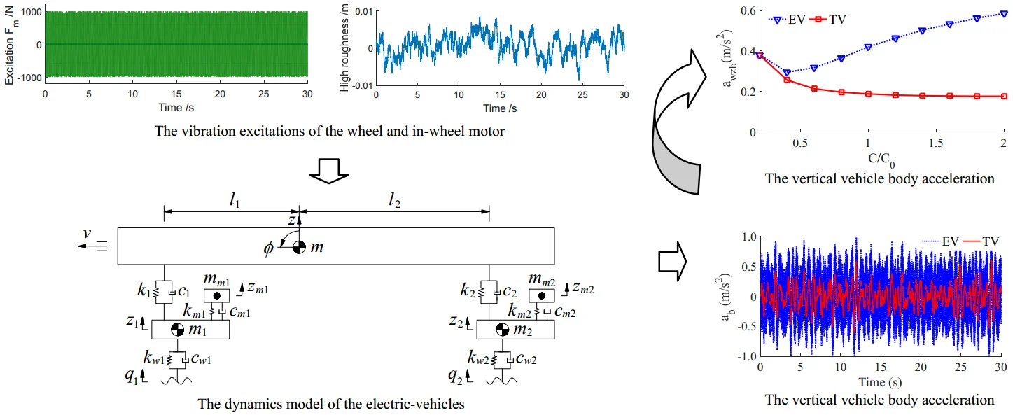
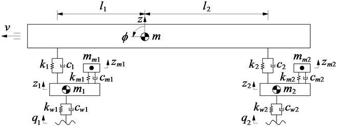
A non-linear dynamics model of the EV using the IWM is established to study the EV ride comfort, as shown in Fig. 1, where , , and are the displacements in the vertical motion of the EV body, front-read axles, and front-rear IWMs, respectively; is the displacement in the pitching motion of the EV body; , , and are the masses of the EV body, front-rear axles, and IWMs, respectively; and are the stiffness and damping coefficients of the EV’s suspension system; and are the stiffness and damping coefficients of the IWM; and and are the stiffness and damping coefficients of the wheels respectively; and are the vibration excitations of the road surface on the wheels; and are the distance from the centre of gravity of the EV body distribution to the front and rear axles.
Fig. 1The dynamics model of the electric-vehicles
Based on the dynamics model of the EV in Fig. 1, the different motion equations of the EV can be written as follows:
The vertical dynamic equations of the EV suspensions, IWM isolations, and Wheels are determined as follows:
The vertical dynamic equations of and of the EV suspensions.
The vertical dynamic equations of and of the IWM isolations:
The vertical dynamic equations of and of the wheels:
The vibration excitation forces and of the IWM are determined in Section 2.2.
2.2. Excitation vibration sources
In the EV's moving condition, two excitation sources of the vehicle include the excitations of front-rear in-wheel motors and the excitations of the random road surface at the front-rear tyres. The vibration excitations are determined as follows:
The vibration excitations ( and ) of the IWM.
The nonlinear dynamic model of the in-wheel motor driving of the EV was researched and applied [3, 4]. Based on the vibration model of the EV, the excitation forces of the in-wheel motor are determined as follows:
where, is the radius of the tyre, is the moving velocity of the vehicle, is the eccentricity of the rotor or tyre, is the total mass of the motor rotor and tyre, and is the angular velocity of the rotor or tyre.
Based on the simulation result of Wang [6], the excitation force of the IWM at the speed 20 m/s of the EV in Fig. 2(a) is then used for this study.
Fig. 2The vibration excitations of the wheel and in-wheel motor [6]
![The vibration excitations of the wheel and in-wheel motor [6]](https://static-01.extrica.com/articles/21862/21862-img2.jpg)
a) Excitation force of the in-wheel motor
![The vibration excitations of the wheel and in-wheel motor [6]](https://static-01.extrica.com/articles/21862/21862-img3.jpg)
b) Excitation of road surface roughness
The vibration excitation ( and ) of the random road surface at front and rear wheels.
In order to describe the road surface roughness, the white noise speed spectrum represented with a realization of a random process via its frequency spectrum density (FSD) has been used to calculate the road surface roughness in the time region. The vibration equation is expressed as follows [16]:
where, is the signal of the white noise function, is the power spectrum density of the road, and is the spatial frequency of the road surface.
Based on the result in Ref. [6], the excitation of the rough road surface at the tyres of the EV at the speed 20 m/s plotted in Fig. 2(b) is also used for this study.
3. Simulations and discussions
In the EV moving condition, the dynamic parameters of the EV affect greatly on the EV ride comfort. In order to improve the EV ride comfort, the influence of the different operation conditions on the EV ride comfort will be concerned in this study. To evaluate the EV ride comfort, the weighted root-mean-square (RMS) acceleration responses of the vertical vehicle body () and pitching vehicle body angle () are used as objective studies. Their equations are described as follows [17]:
where, and are the acceleration responses of the vertical vehicle body and pitching vehicle body angle, and is the simulation time.
In order to evaluate the EV ride comfort, the simulation results of the EV under the different conditions are then compared with the traditional vehicle without EV (TV) via two indexes of the and .
3.1. Influence of the electric-vehicle suspension parameters
3.1.1. Influence of the stiffness parameters
To evaluate the influence of the stiffness parameters, a range of the different stiffness of [0.2, 0.4, …, 2.0]× is used to simulate under the vibration excitation of the vehicle in Fig. 2 for both the EV and the TV, other conditions remain unchanged.
The effect of the different stiffness of the vehicle suspension system on the acceleration responses of the vertical vehicle body and pitching vehicle body angle are shown in Fig. 3, and their and values are also shown in Fig. 4.
Fig. 3The acceleration responses under the various stiffness coefficients
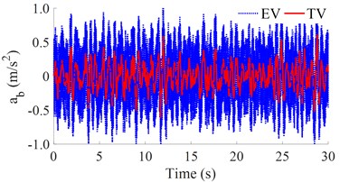
a) The vertical vehicle body acceleration
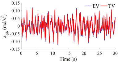
b) The pitching vehicle body acceleration
The simulation results in Fig. 3 show that the acceleration responses of the vertical vehicle body and pitching vehicle body angle with the EV is much higher than that of the TV, especially the vertical vehicle body acceleration response. Thus, the EV ride comfort is strongly reduced compared to the TV.
The RMS results in Fig. 4 show that when the stiffness of the suspension system is increased from 0.2× to 2.0×, both the and values are also quickly increased. This means that the vehicle's ride comfort is reduced when increasing the stiffness coefficient of the suspension system. The simulation result also shows that the value of the EV is strongly increased in comparison with the TV. This is due to the effect of the vibration excitation of the IWM. In order to improve the EV’s ride comfort, the stiffness coefficient of the suspension system of [0.6 to 0.8]× should be chosen. If the stiffness coefficient of the suspension system of [0.2 to 0.6]× is used, the vehicle stability and safety will be reduced.
Fig. 4The RMS acceleration responses under the various stiffness coefficients
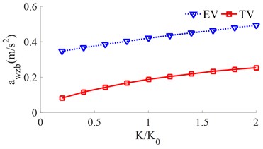
a) The vertical vehicle body acceleration
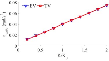
b) The pitching vehicle body acceleration
3.1.2. Influence of the damping parameters
The different damping of [0.2, 0.4, …, 2]× is simulated for both the EV and the TV. The simulation results of the and values are shown in Fig. 5.
With the TV, when the damping coefficient is increased from 0.2× to 2.0×, both the and values are reduced, thus, the ride comfort is improved. Conversely, with the EV, the value is strongly increased with the increase of the damping coefficient of the suspension system. Thus, the EV ride comfort is strongly affected. To solve this problem, the EV’s suspension system needs to optimize or control. Additionally, based on the simulated results in Fig. 5, the damping coefficient of the EV suspension system should be reduced by [0.4 to 0.6]× to improve the EV ride comfort.
Fig. 5The RMS acceleration responses under the various damping coefficients
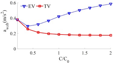
a) The vertical vehicle body acceleration
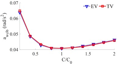
b) The pitching vehicle body acceleration
3.2. Influence of the mass of the electric-vehicle’s unsprung and in-wheel motor
To evaluate the effect of the mass of the electric-vehicle’s unsprung and in-wheel motor on the EV ride comfort, the mass of the and of the EV increased from [0, 0.2 ....2.0]×, meanwhile, the mass of both the EV and TV reduced from [2.0, 1.8 .... 0.2, 0.0]×, are simulated under a speed of 72 km/h and random road surface. The simulation results of the and values are plotted in Fig. 6.
With the TV, when the mass of the vehicle body is reduced from [2.0, 1.8 .... 0.2, 0.0]×, the results show that both the and values are significantly increased, thus, the TV ride comfort is reduced. Conversely with the EV, when both the mass of the and of the EV is increased and the mass of the EV body is reduced by [2.0, 1.8 .... 0.2, 0.0]×, the results of both the and values are strongly reduced. Therefore, the mass distribution between the EV’s unsprung and in-wheel motor greatly affects the EV ride comfort. To improve the EV ride comfort, the mass distribution between the EV’s unsprung and in-wheel motor should be chosen by increasing the and in a range from 1.6× to 2.0× and reducing the in a range from 0.4× to 0.0×.
Fig. 6The RMS acceleration responses under the effect of the various mass distributions
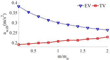
a) The vertical vehicle body acceleration
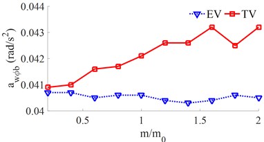
b) The pitching vehicle body acceleration
3.3. Influence of the electric-vehicle speeds
Under the other simulation conditions unchanged, a range of the vehicle speed from 0 to 120 km/h is used to simulate the results. The effect of the EV speed on the ride comfort is shown in Fig. 7.
Fig. 7The RMS acceleration responses under the various moving speeds
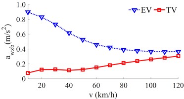
a) The vertical vehicle body acceleration
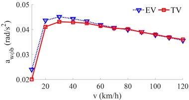
b) The pitching vehicle body acceleration
The result in Fig. 7(a) shows that the of the EV is higher than that of the TV under various speeds. However, when increasing the vehicle speed, the of the TV is increased while the of the EV is strongly reduced. On the contrary, the result in Fig. 7(b) of both the TV and EV is the same. The vehicle shaking is improved when increasing the vehicle speed. Based on the simulated result for the EV, the EV moving speed should be from 80 km/h to 120 km/h to improve the ride comfort.
3.4. Influence of the different excitations of the road surface
In this study, the different conditions of the road surface with its harmonic function and step are also simulated to compare the EV ride comfort. The simulation results of the acceleration responses of the vertical and the pitching vehicle body under a harmonic function and a step of the road surface are indicated in Figs. 8 and 9.
The result in Figs. 8(b) and 9(b) shows that the pitching vehicle body acceleration response with the EV is insignificantly changed in comparison with the TV under both the road surface of the harmonic and step-functions. However, the result in Figs. 8(a) and 9(a) shows that the vertical vehicle body acceleration response with the EV is much higher than that of the TV under both two excitations of the harmonic and step-functions. This is also due to the effect of the vibration excitation of the IWM. Therefore, it can include that the EV equipped with the IWM greatly affects the vehicle's ride comfort under various operation conditions of the EV.
Fig. 8The acceleration responses under a road surface of the sin-function
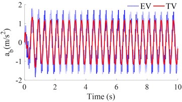
a) The vertical vehicle body acceleration
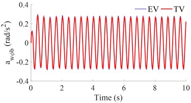
b) The pitching vehicle body acceleration
Fig. 9The acceleration responses under a road surface of the step-function
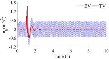
a) The vertical vehicle body acceleration
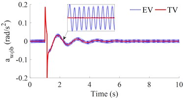
b) The pitching vehicle body acceleration
4. Conclusions
1) The stiffness and damping parameters of the suspension systems of the EV and IWM are greatly affected the EV’s ride comfort.
2) Comparison with the TV, the pitching vehicle body acceleration response with the EV is insignificantly changed while the vertical vehicle body acceleration response with the EV is strongly increased. Thus, the EV ride comfort is significantly reduced in comparison with the TV under the same simulation conditions.
3) The vibration excitations of the IWM greatly affect the EV ride comfort under the various simulation conditions. To improve the EV ride comfort, a range of the optimal dynamic parameters of the damping and stiffness coefficients of the suspensions; and the mass distribution of the vehicle should be used by [0.6 to 0.8]×, [0.4 to 0.6]×, and 1.6× to 2.0×. These proposed values should be optimized or controlled to further improve the vehicle’s ride comfort.
References
-
Hung Y., Wu C. A combined optimal sizing and energy management approach for hybrid in-wheel motors of EVs. Applied Energy, Vol. 139, 2015, p. 260-271.
-
Xiong R., Cao J., Yu Q. Reinforcement learning-based real-time power management for hybrid energy storage system in the plug-in hybrid electric vehicle. Applied Energy, Vol. 211, 2018, p. 538-548.
-
Yu Y., Zhao L., et al. Influence of rotor-bearing coupling vibration on dynamic behavior of electric vehicle driven by in-wheel motor. IEEE Access, Vol. 7, 2019, p. 63540-63549.
-
Le V., Bui V., et al. Effect of in-wheel motor suspension system on electric vehicle ride comfort. Vibroengineering Procedia, Vol. 29, 2019, p. 148-152.
-
Jin L., Yu Y., Fu Y. Study on the ride comfort of vehicles driven by in-wheel motors. Advances in Mechanical Engineering, Vol. 8, Issue 3, 2016, p. 1-9.
-
Wang P. Effect of electric battery mass distribution on electric vehicle movement safety. Vibroengineering Procedia, Vol. 33, 2020, p. 78-83.
-
Abdussalam A. O., Özkan B. Analysis of effect of in-wheel electric motors mass on passive and active suspension systems. ARPN Journal of Engineering and Applied Sciences, Vol. 10, Issue 17, 2015, p. 5924-5928.
-
Liu M., Gu F., Zhang Y. Ride comfort optimization of in-wheel-motor electric vehicles with in-wheel vibration absorbers. Energies, Vol. 10, 2017, p. 1647.
-
Ma F., Wang J., Wang Y., Yang L. Optimization design of semi-active controller for in-wheel motors suspension. Journal of Vibroengineering, Vol. 20, Issue 8, 2018, p. 2908-2924.
-
Luo Y., Tan D. Study on the dynamics of the in-wheel motor system. IEEE Transactions on Vehicular Technology, Vol. 61, 2012, p. 3510-3518.
-
Liu M., Gu F., Huang J., Wang C., Cao M. Integration design and optimization control of a dynamic vibration absorber for electric wheels with in-wheel motor. Energies, Vol. 10, 2017, p. 2069.
-
Tan D., Lu C., Zhang X. Dual-loop PID control with PSO algorithm for the active suspension of the electric vehicle driven by in-wheel motor. Journal of Vibroengineering, Vol. 18, Issue 6, 2016, p. 3915-3929.
-
Nguyen V., Zhang J., et al. Performance analysis of air suspension system of heavy truck with semi-active fuzzy control. Journal of Southeast University, Vol. 33, Issue 2, 2017, p. 159-165.
-
Nguyen V., Zhang J., Jiao R., et al. Effect of the off-road terrains on the ride comfort of construction vehicles. Journal of Southeast University, Vol. 35, Issue 2, 2019, p. 191-197.
-
Yuan H., Nguyen V., Zhou H. Research on semi-active air suspensions of heavy trucks based on a combination of machine learning and optimal fuzzy control. SAE International Journal of Vehicle Dynamics, Stability, and NVH, 2021, (in Press).
-
Nguyen V., Jiao R., Zhang J. Control performance of damping and air spring of heavy truck air suspension system with optimal fuzzy control. SAE International Journal of Vehicle Dynamics, Stability, and NVH, Vol. 4, Issue 2, 2020, p. 179-194.
-
Nguyen V., Wu Z., Zhang J., Zhang B. Vibration analysis and control of vibration screed system of asphalt paver through experimental and simulation. IJAV, Vol. 25, Issue 3, 2020, p. 363-372.
Cited by
About this article

This research was supported by Open Fund Project of Hubei Key Laboratory of Intelligent Transportation Technology and Device, Hubei Polytechnic University, China (No. 2020XY105) and Talent Introduction Fund Project of Hubei Polytechnic University (No. 19XJK17R).
