Abstract
This paper introduces a novel tumbleweed rover design that employs a pipe-type energy harvester system to harvest electrical power from the wind indirectly. The critical parameters law of electromagnetic induction is studied firstly and then propose a preliminary model of the layout of harvesters. Simulates the motion of the harvester inside a spherical shell to achieve the performance of voltage generation and summarize the varying rules of induced voltage. Given the effect of centrifugal force, we further propose spring as a solution to support magnet to recover reciprocating motion in harvester. Finally, the experiments are implemented based on the simulated model to verify the dependability of the energy harvester and the validity of induced voltages’ varying rules.
1. Introduction
Due to the unique shape and distinctive motion characteristics, spherical mobile robot is well recommended to be utilized in scientific research of harsh environment fields such as the Antarctic and Arctic investigation. The Antarctic is abundant with windy resource with high average speed, therefore some researchers proposed passive-drive spherical robot, which means the ball is actuated by the wind without any drive system inside the robot. Tumbleweed Polar Rover is an inflatable spherical mobile robot, which invented by NASA JPL in 2001, the pipe inside the shell use to adjust the posture, set up micro-controller and some communication devices. Inflatable Tumbleweeds have been tested about 4 days by NASA JPL in Greenland and Antarctica [1, 2]. NASA has also designed the Box Kite to investigate Mars, its kinematic principle refers to tumbleweed, robot’s structure is innovated based on the random windy environment in order to enhance the controllability of robot motion [3-5].
However, the robot needs continuous power to keep sensors and controllers working, it will be a problem when there is less energy. It’s hard to exchange the battery for robot because of the random motion of robot and harsh environment. So, the ability of harvesting energy would like to be a significant function for robot. Liquid Robotics’ Wave-Glider is a submerged glider tethered to a floating buoy, which utilizes wave-energy to produce forward motion while using solar energy to power on-board electronics [6].
Another approach to cover larger distances is to employ a pendulum converting Tumbleweed's kinetic energy to electrical power, which can then be stored in a battery or similar energy storage device [7]. Bryan Steven Joyce, studied in Virginia Polytechnic Institute and State University, proposed a kind of electromagnetic energy harvester for monitoring wind turbine blades in 2011 [8, 9]. In 2012 the NASA developed another wind-propelled Moball with energy scavenging system inside it [10-12].
In this paper, we introduce and study employs a novel pipe-type energy harvester Tumbleweed Rover design that own a number of potential advantages over its competitors:
1. It employs an internal pipe-type energy harvester system to produce electrical power as a result of being driven by the wind. Using Tumbleweed's kinetic energy in order to generate abundant power for the payload.
2. Pipe-type energy harvesters are very fit for sphere, it is convenient to install these harvesters inside the tumbleweed rover.
3. These pipe-type layout symmetry in space and therefore the generatered electrical power by pipe-type energy harvester system can be balanced and also easier for storage.
This work focuses on developing a method to efficiently harvest wind energy. In order to understand allthe factors impacting the capability of electrical power generation, a test platform was developed. Relationships between different design parameters about pipe-type energy harvester in robot will be present, and we will consider the distribution of energy harvesters from plane to space in order to implement balanced energy harvesting in the future.
2. Energy harvester design and analysis
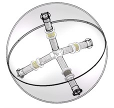
Considering the robot’s inner structure, the main parts include energy harvesters, some sensors and controller which used for data collection and transmission [13]. Therefore, distribute and employ an internal pipe-type energy harvester system inside sphere properly is the most important thing. However, we wonder seek the answer in different perspectives and hope be inspired from the natural symmetry structures. So, we proposed these patterns according to variable symmetrical spatial model such as the chemical formula of methane or biological like dandelion and tumbweek etc. The robot’s conceptual structure is shown in Fig. 1(a). All the patterns we considered would be shown a highly symmetric in the sphere. Because a symmetrical structure will benefit the equilibrium of energy collection and be a guarantee of gathering enough power while sphere is moving in arbitrary direction.
2.1. Pipe-type energy harvester design
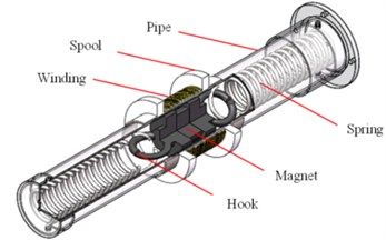
The pipe-type energy harvester design is shown in Fig. 1(b) mainly consisted of pipe, magnet, hook, coil winding and spring. The coil winding is tightly wounded on a spool, which is fixed on the pipe. The magnet and spring lay inside the pipe with two hooks absorbed at both ends of magnet in order to connect with spring (or without spring). And both side of spring fixed on the end of pipe. The total device can be considered as a module with modifiable dimension based on the pipe distributed structure. The parameters related to spring, magnet, winding such as stiffness, mass or diameter could also be changed as some certain requirement [14, 15].
When sphere gets rotating with the wind, the inner energy harvesters follows, then the magnet begin to move back and forth in the pipe, that’s the original mechanism to create induced voltage. In addition, given the strong windy environment at the Antarctic, the sphere will obtain a high speed, therefore the magnet would stuck at the end of the pipe because of centrifugal force without any movement. So, this paper put forward spring as a kind of solution. When the centrifugal force pushes magnet forward to the end, the spring keeps dragging magnet to move it back. The spring not only assists magnet to overcome the centrifugal force, but also increases the frequency of the motion with more induced voltage as a result.
Fig. 1a) Conceptual structure; b) tubular energy harvester structure
a)
b)
2.2. Electrodynamic induction equations and critical parameters
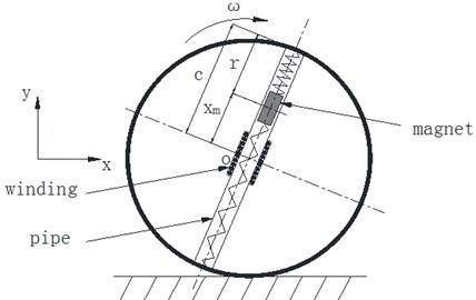
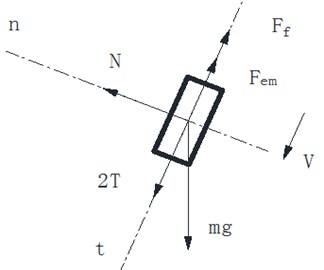
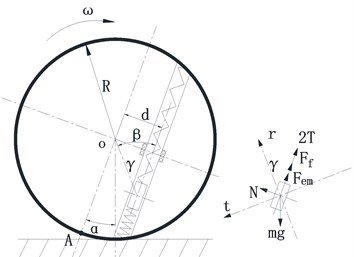
As mentioned above, this paper refers Faraday’s law of electromagnetic induction as basic theory, which said that the induced voltage comes when the magnetic flux in closed coil alters. Fig. 2 shows sphere structure diagram and the forces applied to magnet which include gravity (), friction () with pipe, support force (), elastic force (), electromagnetic drag force () [7, 16]. Applying Newton’s Law to the magnet we can infer the equation of magnet:
The acceleration of magnet is supposed to be the value that cause by the acceleration after total force offset the centrifugal force [17].
Fig. 2a) Sphere structure diagram; b) forces diagram of magnetic
a)
b)
According to the Faraday’s law of electromagnetic induction, the equation of induced voltage can be given by [18]:
, named as coupling factor, is the function with variable , which applied to replace the product of varying magnetic flux () and the length () of closed coil. The derived is velocity of magnet. The equation of has been given by [19]:
From the formula derivation above, we can see that the induced voltage is expressed as the product of coupling factor and magnet’s velocity . And is related to the features of coil such as length, volume and thickness, velocity can be calculated by Eq. (1). The variables which affect the induced voltage can be considered as critical parameters to help to validate our design. The velocity here is the relative speed between magnet and winding when magnet pass through the winding. Our work will be focus on how to make magnet obtain the optimum speed when it across the winding. The optimum speed means that the magnet can move both fast enough and equilibrium enough in spite of the ball’s speed. That is to say, the velocity’s peak value fluctuates in a small range. The effects of critical parameters on the induced voltage will be analyzed in next section.
3. Dynamic simulations
In order to observe the voltage generation law and investigate the influence of each critical parameter, this paper takes numerical simulation and kinematic simulation to research the motion of magnet, and selects the optimum parameters according to the motion’s characteristics to reach energy generation equilibrium. During the simulation, MATLAB and ADAMS have been used. We consider it as ideal condition, so there will be no energy loss and each solenoid is assumed to be tightly wound. The paper first analyzes the motion of one single pipe before researching spatial distribution of multiple pipes. The layout of pipe is divided into two cases, which are center and eccentricity. The simulation results of these two conditions will be compared to conclude both their merits and demerits.
3.1. Critical parameters simulation of centered pipe
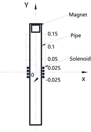
Centered layout of single pipe is the foundation of planar and spatial layout of multi-pipe. Centered layout, which means the center of pipe is coincided with the center of sphere, could be installed on any diameter direction. The key variables that affect induced voltage are mainly the winding and magnet. The major parameters of winding are total length and its position on the pipe. The major parameter of magnet is mass. In addition, the rotational speed of sphere is another primary variable. This paper will mainly discuss these parameters.
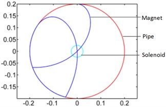
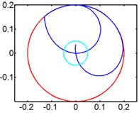
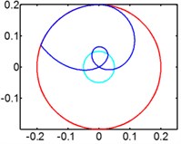
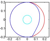
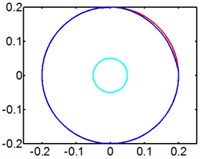
Effect of winding’s position. Fig. 3(a) illustrates the theoretical model of centered pipe which rotates around point O. Fig. 3(b) shows the trajectory of magnet and the range of pipe and winding.
The dash line in Fig. 4 shows the winding’s position varies along axis. These 4 positions are (–0.025 m, 0.025 m), (0 m, 0.05 m), (0.05 m, 0.1 m), (0.1 m, 0.15 m). The distance between winding and pipe is gradually increasing from first position to fourth position.
Fig. 3a) Theoretical model of pipe; b) trajectory of magnet
a)
b)
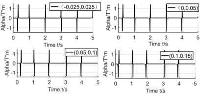
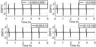
Fig. 4Effect of winding’s position on coupling factor and induced voltage
a)
b)
From the simulation results, it can be seen that the position of winding has no relation with , but a significant influence for the induced voltage. Because different winding positions cause different relative speed when magnet moves across the winding. When rotating in a lower speed, the magnet passes through winding twice in one circle. We can see that the difference of induced voltage is higher when the winding position is closer to the end of pipe. But when the winding position is close to the center of pipe, both relative speeds are almost same, then the difference of voltage is lower too.
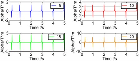
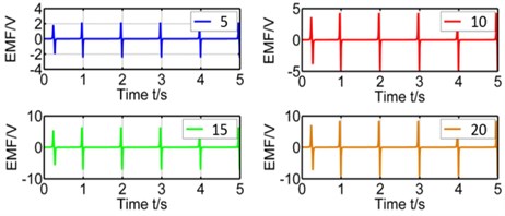
Effect of winding’s layers. The number of winding’s layers is proportional to the total length of winding which affects the coupling factor () a lot. The winding's layers have been set as 5 layers, 10 layers, 15 layers and 20 layers and their simulation results on coupling factor and induced voltage are showed in Figure 5 respectively.
Fig. 5Effect of winding's layers on coupling factor and induced voltage
a)
b)
Table 1 shows the peaks of voltage and . From figures and tables, we could tell that is directly proportional to the winding’s layer. Because more layers mean more total length of closed coil.
Effect of sphere’s rotating speed. The sphere’s rotating speed affect the relative velocity between the magnet and pipe, therefore the wind speed should be seriously concerned as a great variable in Antartic. The peaks of induced voltage and their corresponding rotating speeds are shown in Table 2.
Table 1Peaks of induced voltage
Winding layer / mm | 5 | 10 | 15 | 20 |
Induced voltage / V | 2.46 | 4.85 | 7.12 | 9.25 |
Table 2Peaks of induced voltage
Rotating speed / rpm | 30 | 40 | 50 | 60 |
Induced voltage / V | 2.29/2.61 | 2.05/2.29 | 1.10/1.63 | 0 |
Fig. 6(a) and 6(b) show the curve of induced voltage and the velocity of magnet respectively. When the rotating speed increases, induced voltage will gradually decrease. And the higher of rotating speed, the lower of relative velocity’s amplitude.
In Fig. 7 we can infer that magnet moves gradually to the end of pipe, so there is no relative motion between magnet and winding anymore, either no induced voltage. So higher rotating speed will weaken the energy generation ability of harvester. We give spring to optimize the energy harvester to solve the centrifugal problem caused by high rotating speed.
Fig. 6Effect of rotating speed
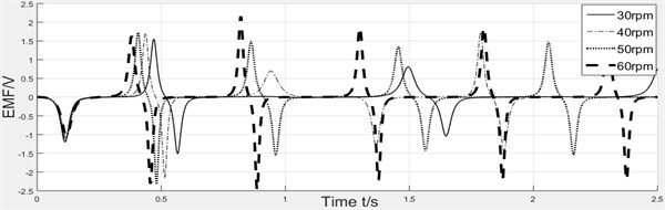
a) Curve of induced voltage
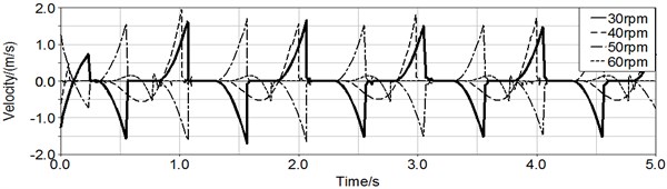
b) Curve of magnet velocity
Fig. 7Track of magnet motion
a) 30 rpm
b) 40 rpm
c) 50 rpm
d) 60 rpm
When magnet moves forward to the pipe end, the spring restrains its centrifugal motion to provide restoring force for magnet. The critical parameter of spring is stiffness , which is related to spring diameter, length, external diameter etc. So, stiffness should be researched before determining to choose the optimum spring. The formula of can be inferred from mechanical analysis as:
We take the maximum value of stiffness to demand the whole moving process. Once determining the stiffness of spring, we simulate the magnet’s motion with and without spring to conclude the spring’s effect. The stiffness of spring is set as 0 N/m, 25 N/m, 35 N/m, 45 N/m, 55 N/m. Fig. 8 shows the simulation results which are the velocity curve and displacement curve of magnet and induced voltage. Table 3 lists the peaks of induced voltage and it can be clearly seen that spring really assists magnet to overcome centrifugal force but with a limit. The spring with excessive stiffness conversely resists the motion of magnet. So, we could infer that the different stiffness of spring is helpful within a special range of rotating speed.
Table 3Peaks of induced voltage
Spring stiffness / (N/m) | 0 | 25 | 35 | 45 |
Induced voltage / V | 0 | 2.17/2.33 | 2.27/2.27 | 1.58/1.59 |
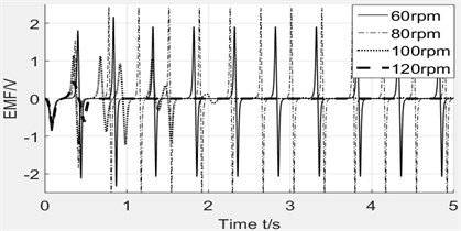
When the rotating speed keeps increasing, the motion of magnet may have different performance, therefore the rotating speed is set as variable to investigate its influence on the magnet. The speeds have been set as 60 rpm, 80 rpm, 100 rpm, 120 rpm. Fig. 9 illustrates the effect of rotating speed on induced voltage. The induced voltage is raising when speed increases from 60 rpm to 80 rpm, but drops down rapidly from 80 rpm to 120 rpm. So, the spring with one fixed stiffness will only be suitable for a small range of speed environment. When the speed exceeds the critical value, the spring will not work. Therefore, we can find optimum spring for the practical situation.
Fig. 8Effect of spring stiffness
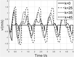
a) Velocity curve
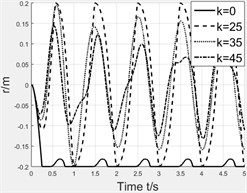
b) Displacement curve
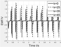
c) Induced voltage
Fig. 9Effect of rotating speed on induced voltage
3.2. Contrast simulation of eccentric pipe
The research would like to distribute the pipes orderly inside the sphere which are related to planar layout and spatial layout. The parts of pipes which can’t pass the center are called eccentric pipes. It’s necessary to research the laws of magnet’s motion and the variation of induced voltage under variable parameters, which would be benefit to future study.
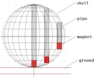
We analyze the force condition of magnet applied Newton’s Law as shown in Fig. 10(a). There are much more variables than centered pipe, including radius vector between magnet and sphere’s center, angle between pipe and the line between magnet and sphere’s center etc. These variables determine the value and direction of centrifugal force, which make it hard to solve the equation, so this paper creates simplified model based on the equation, and utilize Adams to simulate the motion of sphere, pipe and magnet. In addition, we focus on the simulation of motion, so we set parameters of winding as fixed values, then the coupling factor is fixed too. We obtain the velocity when magnet across winding, then the induced voltage can be calculated. Fig. 10(b) illustrates the sphere model without spring in Adams. We named the three pipes as long pipe (490 mm), medium pipe (430 mm) and short pipe (210 mm), the distance between adjacent pipes is 100 mm. The motion of magnet will be simulated and discussed with and without the spring.
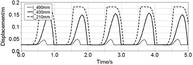
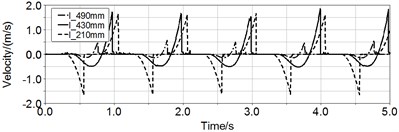
The displacement and velocity () of magnet without spring in Fig. 11 illustrate the motion of magnet has the traits of simple harmonic motion. When rotating speed is 60 rpm, the displacement and velocity of centered pipe’s magnet are almost zero. But the maximal displacement of medium pipe and short pipe is respectively 0.18 m and 0.16 m, and their maximal velocity are respectively 1.95 m/s and 1.66 m/s. However only the magnet in short pipe can move back and forth in the whole pipe, the magnet in medium pipe can only move in half of the pipe.
Fig. 10a) Force of eccentric magnet; b) Adams model of sphere
a)
b)
Fig. 11Curves of displacement and velocity of magnet in three pipes
a)
b)
In general, eccentric pipe can eliminate the effect of centrifugal force at high rotating speed. The more the eccentric distance, the less the effect of centrifugal force. Because when eccentric pipe rotates around the center, the tangential speed direction and resultant direction of magnet own some projection components on the pipe direction in some time, even overlap with each other, that’s why the magnet can move along pipe. But the tangential speed direction and pipe direction of magnet in centered pipe, which is also long pipe, is always mutually perpendicular without projection component, therefore there is no movement of the magnet.
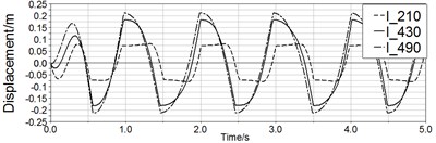
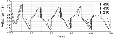
Fig. 12 is the simulation results with spring. After applying the spring, the motion of magnet in long pipe and medium pipe have been improved which means magnet can move through whole pipe. The maximal displacement of magnet in long pipe and medium pipe are respectively 0.21 m and 0.18 m, and this value of short pipe is 0.16 m. Therefore, the spring helps to restore reciprocating motion apparently.
Fig. 12Curves of displacement and velocity of three pipe
a)
b)
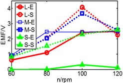
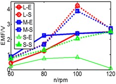
In order to test the spring's effective working range under different rotating speeds, we set the rotating speed () and spring stiffness () as variables and calculate the induced voltages through simulation. The different performance of the magnet in three kinds of pipes under the variable parameters are shown in Fig. 13 and then the varying law is concluded.
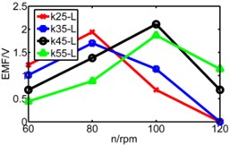
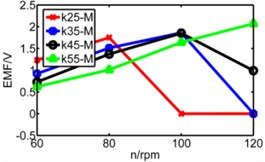
The coupling factor () is calculated through MATLAB, and finally getting the value of induced voltage by equation (4). Fig. 13 is comparison diagram of three pipes’ induced voltages, axis is rotating speed. , , represents respectively long pipe, medium pipe and short pipe. We can see that the induced voltage of short pipe is more stable and balanced than that other pipes especially under lower spring stiffness.
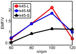
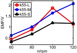
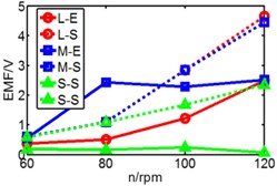
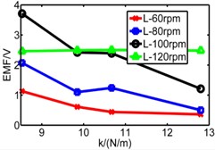
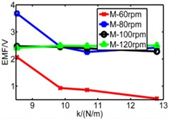
From above figures we can’t distinguish the strengths and shortcomings of long pipe and medium pipe, therefore the three kinds of pipes are separated in three diagrams in Fig. 14 to analyze three pipes’ induced voltages. The spring stiffness () increases from 25 N/m to 55 N/m as shown below.
Fig. 13Comparison diagram of three pipes’ induced voltage
a) 25N/m
b) 35 N/m
c) 45 N/m
d) 55 N/m
Fig. 14Diagram of three pipes’ induced voltage with rotating speed to be X axis
a) Long pipe
b) Medium pipe
c) Short pipe
4. Experiments
The analysis and simulation results above have already revealed the basic theory of electric power generation. The experiments would be implemented in this chapter to prove the effect of critical parameters on induced voltage. And then comparing the experimental results and simulation results of three different lengths of pipes’ electric generation.
4.1. Experimental device
Fig. 15 illustrates the laboratory prototype which simulates the rotation of spherical mobile robot. The prototype is composed by the module of electric generation and the module of drive system.
We use enameled wire to make windings as shown in Fig. 15(b) with three kinds of different layers to prove the simulation results. The width of windings is 20 mm, and the diameter of wire is 0.5 mm.
The module of drive system includes step motor, special driven shaft, bearings and bearing block, acrylic disk. Step motor is fixed on the desk, the output shaft of motor connects with special driven shaft, which is fixed on the acrylic disk and supported by bearings. So, the rotating of step motor can drive the rotation of acrylic disk accurately.
The module of electric generation includes PVC transparent pipe, permanent magnet, windings and ATmega128 SCM. The magnet can move back and forth in the inner of the pipe and the windings are tightly wounded on the spool to fixed on the pipe. At the two both ends of coils are linked with the ports of ATmega128.
Fig. 15Experimental device
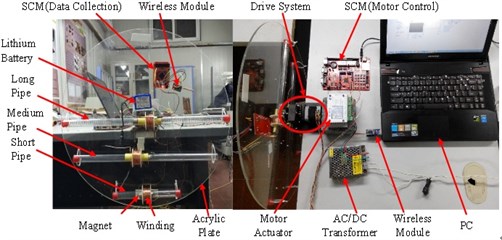
a) Laboratory prototype
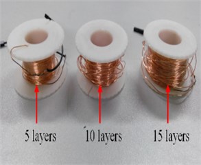
b) Diagram of windings
4.2. Experimental results
Considering the long pipe is the most sensitive one to critical parameters which is also centered pipe, is proposed to test and verify the simulation results. The critical parameters include winding’s position, winding’s layer, rotating speed of sphere and spring stiffness.
Winding’s positions. The winding’s positions are set as (–0.01 m, 0.01 m), (0.05 m, 0.07 m), (0.1 m, 0.12 m) and (0.15 m, 0.17 m) and Fig. 16 illustrates the experimental results respectly.
Fig. 16Comparison diagram of experiment and simulation
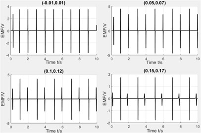
a) Simulation results
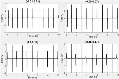
b) Experiment results
From the above results, we can see that the more of the distance between winding and pipe center, the more of the induced voltage’s peaks, but the difference between two peaks will also be increased. The varying rule of experiment and simulation is basically same and the value of experiment is slightly less than simulation because the circuit friction between magnet and pipe, and the circuit will also consume energy.
Winding’s layers. The number of winding's layers have been set as 5 layers, 10 layers and 15 layers. Fig. 17 shows the curve of induced voltage. As can be seen from the figure, the more layers, the higher the induced voltages. So, the assumption that coupling factor is positively proportional to the total length of winding is proved. But it should be concerned that excessive layers are also inadvisable, which not only will increase the resistance, but also the total mass of energy harvester, it’s negative for the layout of multi-pipes. So, the number of layers should be determined together with other parameters.
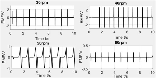
Rotating speed. The rotating speed has been set as 30 rpm, 40 rpm, 50 rpm and 60 rpm. In the experimental process, when the rotating speed is increased, the displacement and velocity of magnet begin to decrease, then the induced voltage also drops. The experimental results can be seen in Fig. 18.
Fig. 17Diagram of induced voltage with varying winding layers
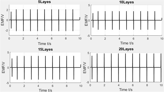
Fig. 18Experimental results
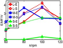
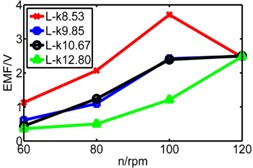
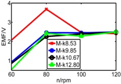
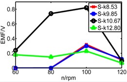
It’s can be seen from the analysis above that the decrease of induced voltage is caused by centrifugal force and gives spring as a solution. To prove the effect of spring on restoring the reciprocating motion of magnet, this paper takes the compression spring of which the wire diameter is 0.4 mm and the external diameter is 10 mm and then cut the spring to obtain four different lengths. And the stiffness of four spring, respectively, is 8.53 N/m, 9.85 N/m, 10.67 N/m, 12.8 N/m. Fig. 19 shows the three pipes’ experimental results which sets the stiffness and rotating speed as variables.
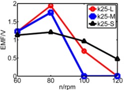
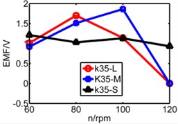
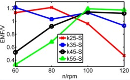
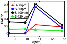
In Fig. 19, dash line S represents simulation result, solid line represents experimental result, is long pipe, is medium pipe, is short pipe. According to the results, there are some fluctuations of experimental data and generally the value of induced voltage is less than that of simulation results. With the increase of stiffness, only higher rotating speed can ensure the reciprocating motion of magnet.
We can infer from Fig. 19 that higher stiffness and lower rotating speed will restrain the motion of magnet. But higher speed improves the induced voltage. When the speed rises to 80 rpm, both peaks of induced voltage are close to 2.3 V, but when speed reaches 100 rpm and 120 rpm, the difference between two peaks become bigger. So, the conclusion that the magnet owns a suitable spring stiffness () within a limited speed range is verified. According to the results, the performance of long pipe and medium pipe are close to each other. This conclusion is same with simulation. However, the performance of short pipe is different and the maximum of its voltage is less than 1 V, which is obviously different with simulation which is 2 V. The reason is that the distinction of spring’s property between experiment and simulation. In the simulation model, spring has no limited deformation, so the value of deformation in simulation is greater than the value in experiment. In addition, the total length of the two spring exceeds the length of short pipe which causes initial compression. So maybe the spring isn’t suitable for short pipe, a more applicable device for short pipe should be considered in further work.
In addition, according to the varying rules that we have summarized, the pipe with a higher spring stiffness, the induced voltage should be increased with the raise of rotating speed, but in the figure, we can see that the results of 120 rpm and 100 rpm are similar without distinct difference. We have found that the reason is derived from spring. There is a limited deformation of spring. We can infer that when it comes to 100 rpm, the spring has already reached a limited deformation, so the induced voltage has no space to increase.
Fig. 19Comparison of three pipes’ induced voltage peaks when k is 8.53/9.85/10.7/12.8
a) 8.53 N/m
b) 9.85 N/m
c) 10.7 N/m
d) 12.8 N/m
Fig. 20Comparison diagram of three pipes’ induced voltage
a) Long pipe
b) Medium pipe
c) Short pipe
d) Long pipe
e) Medium pipe
f) Short pipe
5. Conclusions
In summary, an electromagnetic energy harvester was proposed for the energy sustained supply problems of spherical mobile robot in the Antarctic investigation. First, we analyzed the dynamics of sphere and magnet and studied the principle of induced voltage with critical parameters. Second, the energy harvester model was built and simulated to obtain the curves of induced voltage, and then the varying rules of induced voltage was analyzed and assumed beneath variable parameters. Finally, we set up the experiments to verify the simulation, and the results prove that the energy harvester can generate voltages which is up to 2.5 V. And we have also concluded a pile of rules among induced voltage and variable parameters. All of these as a basis for the practical application of this system. The future work will focus on the spatial symmetry-layout of pipe-type harvesters inner the sphere.
References
-
Behar A., Jones J., Carsey F. NASA/JPL tumbleweed polar rover. IEEE Aeroconference, 2004.
-
Lori Southard, Thomas M. Hoeg, Daniel W. Palmer, et al. Exploring Mars using a group of tumbleweed rover. IEEE International Conference on Robotics and Automation, Italy, 2007.
-
Rose S. E., Moody C. B., James D. L., et al. Drag measurement and dynamic simulation of Martianwind-driven sensor platform concepts. Journal of Fluids and Structures, Vol. 22, Issue 1, 2006, p. 21-43.
-
Flick J., Toniolo M. Preliminary dynamic feasibility and analysis of a spherical, wind driven (tumbleweed) Martian rover. 43rd AIAA Aerospace Sciences Meeting and Exhibit, 2005.
-
Antol J. A new vehicle for planetary surface exploration: The Mars tumbleweed. 1st Space Exploration Conference: Continuing the Voyage of Discovery, Orlando, Florida, 2005.
-
Olson Robert A. Communications architecture of the liquid robotics wave glider. 3rd IFAC Workshop on Navigation, Guidance and Control of Underwater Vehicles, 2012, p. 255-259
-
Forbes J. R., Barfoot T. D., Damaren C. J. Dynamic modeling and stability analysis of a power-generating tumbleweed rover. Multibody System Dynamics, Vol. 24, Issue 4, 2010, p. 413-439.
-
Bryan Steven Joyce Development of an Electromagnetic Energy Harvester for Monitoring Wind Turbine Blades. Blacksburg Virginia, 2011.
-
Park G., Rosing T., Todd M. D., et al. Energy harvesting for structural health monitoring sensor networks. Journal of Infrastructure Systems, Vol. 14, Issue 1, 2008, p. 64-79.
-
Burkhardt Matthew R., Davoodi Faranak, Burdick Joel W., et al. Energy harvesting analysis for moball, aself-propelled mobile sensor platform capable of long duration operation in harsh terrains. IEEE International Conference on Robotics and Automation, Hong Kong, 2014, p. 2665-267.
-
Davoodi F., Davoudi F. Design for the structure and the Mechanics of Moballs. NASA Tech Brief, 2012.
-
Asama J., Burkhardt M. R., Davoodi F., et al. Design investigation of a coreless tubular linear generator for a Moball: A spherical exploration robot with wind-energy harvesting capability. IEEE International Conference on Robotics and Automation, 2015, p. 244-251.
-
Kim Y., Lim J., Choi H. Y., et al. Starting mode analysis of tubular-type linear generator for free-piston engine with dynamic characteristics. IEEE International Conference on Electrical Machines and Systems, 2007, p. 926-929.
-
Zuo L., Scully B., Shestani J., et al. Design and characterization of an electromagnetic energy harvester for vehicle suspensions. Smart Materials and Structures, Vol. 19, Issue4, 2010, p. 045003.
-
Baker N. J., Mueller M. A., Spooner E. Permanent magnet air-cored tubular linear generator for marine energy converters. Second International Conference on Power Electronics, Machines and Drives, Vol. 2, 2004, p. 862-867.
-
Zhang S., Fang X., Zhou S., et al. Kinetic model for a spherical rolling robot with soft shell in a beeline motion. Journal of Multimedia, Vol. 9, Issue 2, 2014, p. 223-229.
-
Hughes P. C. Spacecraft Attitude Dynamics. Courier Corporation, 2012.
-
Cannarella J., Selvaggi J., Salon S., et al. Coupling factor between the magnetic and mechanical energy domains in electromagnetic power harvesting applications. IEEE Transactions on Magnetics, Vol. 47, Issue 8, 2011, p. 2076-2080.
-
Donoso G., Ladera C. L., Martin P. Magnet fall inside a conductive pipe: motion and the role of the pipe wall thickness. European Journal of Physics, Vol. 30, Issue 4, 2009, p. 855-869.
About this article

This research was jointly sponsored by the Shanghai Municipal Education Commission and State Lead Academic Discipline Fund (Project No. 12ZL1410700), the National High-tech R&D Program of China (863 Program, Grant No. 2011AA040202) and the China Scholarship Council Fund (File No. 201208310055), which are greatly appreciated by the authors.
Yuyi Zhai gives a preliminary model of the energy harvester. Liang Kang simulate the motion of magnet in harvester and the critical parameters. Yuanyuan Sun and Macong Li give the spring as a method to eliminate the centrifugal force. Liang Liu conclude the varying rules of the harvesters.
