Abstract
The paper is aimed at investigating the motion conditions of the wheeled vibro-impact locomotion system equipped with the twin crank-slider excitation mechanism and the additional braking mechanisms allowing only one-way rotation of the wheels. The novelty of the present research consists in the improved mathematical model describing the motion conditions of the vibro-impact system and the proposed parameters optimization technique that allows for maximizing the average translational velocity of the wheeled platform. The main idea of this technique is to provide the maximal velocities of internal bodies when they get in contact with the corresponding impact plates. The numerical modeling results describing the dynamic behavior of the vibro-impact system are obtained in Mathematica software and substantiate the correctness of the developed mathematical model and of the proposed parameters optimization technique. The paper can be of significant practical and scientific interest for researchers and engineers studying and improving the vibratory locomotion systems, e.g., for inspecting and cleaning the pipelines.
Highlights
- The improved design of the wheeled vibro-impact locomotion system equipped with the twin crank-slider excitation mechanism and the braking mechanism allowing the wheels one-way rotation is proposed.
- The mathematical model describing the vibro-impact system motion is derived and the parameters optimization technique that allows for maximizing the system average translational velocity is proposed.
- Providing the vibro-impact operational conditions, the stepwise (discontinuous) translational motion of the wheeled platform is studied by means of numerical modeling in the Mathematica software.
- The obtained results were used while designing and implementing the improved vibratory locomotion system for inspecting and cleaning the pipelines.
1. Introduction
The investigations dealing with mathematical modeling and analyzing the dynamic behavior of the vibration-driven locomotion systems are currently of significant interest among researchers and engineers all over the world. One of the most important problems occurring during designing and implementation of such systems consists in providing their most efficient operational conditions. Considering the wheeled locomotion systems, the average velocity factor is of the most significant ones that should be maximized under the other constant conditions. This paper is focused on motion modeling and testing the parameters optimization technique of the wheeled vibro-impact locomotion system with the twin crank-slider excitation mechanism.
Different types of the vibro-impact locomotion systems are thoroughly investigated in numerous scientific papers, e.g. [1]-[4]. The experimental investigations on the self-propelled vibro-impact locomotion system operating under anisotropic friction are presented in [1]. The influence of dry and isotropic friction on the dynamic behavior of a vibro-impact locomotion system is studied in [2]. The paper [3] is devoted to investigating the locomotion conditions of a self-propelled vibration-driven capsule system equipped with the push-type solenoid. In [4], the authors considered the basic approaches to improving the locomotion performance of vibration-driven systems. The paper [5] is dedicated to the parameters optimization problem focused on maximizing the average velocity of the multi-module vibration-driven locomotion robot. The wheeled vibration-driven robot equipped with the inertial vibration exciter (unbalanced rotor) is studied in the papers [6]-[8]. The robot dynamic behavior is thoroughly studied in [6], [7], and the problems of its vibratory system’s parameters optimization are considered in [8].
The analysis of numerous scientific papers (e.g. [1]-[8]) has shown that the problems of implementing the crank excitation mechanisms in the multi-mass vibro-impact locomotion systems are not thoroughly investigated. Therefore, the authors of the present paper have previously studied the improved design of the controllable eccentric-type excitation mechanism [9], investigated the motion conditions of the three-mass vibro-impact system with the crank-slider excitation mechanism [10], and analyzed the possibilities of implementing the proposed excitation mechanism in vibratory compacting equipment [11]. The novelty of the present paper consists in improving the mathematical model and parameters optimization technique of the wheeled vibro-impact locomotion system equipped with the twin crank-slider excitation mechanism and the additional braking mechanisms allowing only one-way rotation of the wheels. The proposed wheeled platform can be implemented in practice for inspecting and cleaning the pipelines.
2. Research methodology
2.1. Dynamic diagram of the wheeled vibro-impact locomotion system
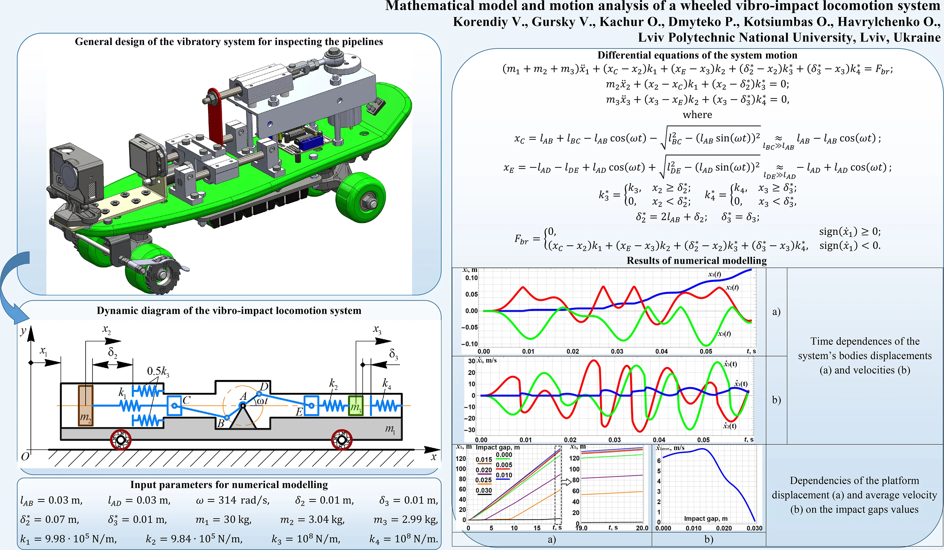
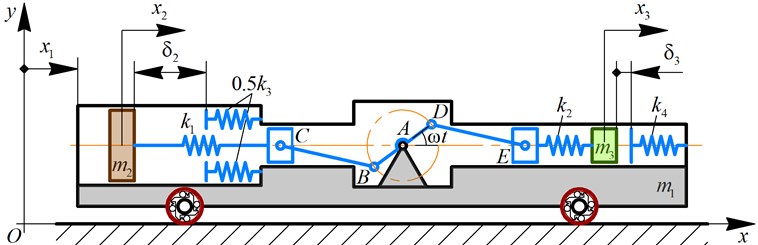
The dynamic diagram of the three-mass vibro-impact system is presented in Fig. 1. The inertial reference frame is adopted to study the translational locomotion of the wheeled platform of the mass . For this purpose, the generalized coordinate is introduced. The twin crank-slider mechanism “ABC-ADE” is used to excite the oscillations of the internal bodies of the masses and . The angular velocity of the crank BAD is considered to be constant, and the initial positions of the crank and the connecting rods BC, DE are the horizontal ones. The relative displacements of the oscillating bodies , with respect to the wheeled platform are described by the corresponding generalized coordinates and . The rotation of the crank BAD is transformed into the translational reciprocating motions of the sliders C and E, which are connected with the internal bodies , by the springs of the stiffnesses , , respectively. The potential energies accumulated in the springs during the sliders reciprocating motions are transformed into the kinetic energies of the internal bodies oscillations.
In order to ensure the translational motion of the wheeled platform, the vibro-impact operational conditions are used. The relative displacements of the internal bodies (masses , ) with respect to the wheeled platform (mass ) are limited by the corresponding impact plates and springs , . When the internal bodies come into contact with the impact plates, their kinetic energies reduce causing the increase in the potential energies of the impact springs. The energies accumulated in the springs are transformed into the kinetic energy of the wheeled platform. In such a manner, the stepwise (discontinuous) translational motion of the platform is performed to the right; the latter is adopted as the forward motion direction. The backward motion (directed to the left) is constrained due to the use of the special braking mechanisms in the wheels allowing only one-way rotation. For example, these mechanisms can be designed as unidirectional (overrunning) mechanical clutches (Fig. 1). While carrying out further parametric synthesis of the vibro-impact system, it is necessary to maximize the average velocity of the wheeled platform.
Fig. 1Dynamic diagram of the vibro-impact locomotion system
2.2. Mathematical model of the system locomotion
In order to develop the mathematical model of the considered vibro-impact system locomotion, the corresponding Lagrange equation of the second kind was derived for each generalized coordinate (, , ). At the present stage of the investigations, all the energy losses are neglected. Three differential equations describing the system locomotion are following:
where , are the functions describing the relative displacements of the sliders C, E with respect to their initial positions; , are the functions describing the change of the stiffness coefficients during the impacts of the corresponding bodies; , are the initial distances between the oscillating bodies and the corresponding impact plates (i.e., the initial impact gaps); is the braking force acting on the wheels when they attempt to rotate in a counterclockwise direction. All the functions and values mentioned above can be expressed as follows:
where , , , are the lengths of the corresponding rods AB, BC, AD, DE forming the crank-slider excitation mechanism; is the angular velocity of the crank BAD; , are the smallest distances between the internal bodies and the corresponding impact plates at the state of rest when the crank angular position is 0 (for the mass ) and (for the mass ).
2.3. Analyzing the basic stages of the internal bodies oscillations
Substituting Eq. (4)-(9) into Eq. (2)-(3), let us solve the obtained system of two differential equations in the Mathematica software considering the following stages. At the first stage, the second body (mass ) moves from its left initial position to the position where it comes into contact with the impact plate: . The third body (mass ) moves from its right initial position to the position where its velocity becomes zero: . For this stage, adopting zero values of the initial conditions , the laws of motion of the corresponding internal bodies are following:
At the second stage, the second body (mass ) moves from the position where it got in contact with the impact plate to the position where its velocity becomes zero: . The third body (mass ) moves from its left position where its velocity became zero to the position where it comes into contact with the impact plate: . For the considered stage, the initial conditions can be presented as follows: , . The laws of motion of the internal bodies are following:
There are much more stages of the internal bodies oscillations. Due to the limited length of the present paper, let us pay major attention to the first two ones describing the starting conditions of the wheeled vibro-impact locomotion system.
3. Results and discussion
3.1. Stating and solving the parameters optimization problem
In the present research, let us consider the optimization problem consisting in maximizing the average translational velocity of the wheeled platform. The largest velocity can be reached in the case when the velocities of the internal bodies reach their maximal values during the contacts of the corresponding impact bodies and plates. Considering the stages of the internal bodies motions analyzed above, the optimization problem can be stated as follows:
The duration of the first stage of the mass oscillations can be determined by substituting into Eq. (11) and solving it with respect to time . Then, by differentiating Eq. (11) with respect to time , the velocity expression of the mass can be derived. Substituting the obtained value of the stage duration into the derived expression , the optimization function can be deduced.
The duration of the first stage of the mass oscillations can be determined after deriving the velocity expression by differentiating Eq. (12) with respect to time and substituting . The solution of the obtained equation with respect to time gives the corresponding duration . Substituting the obtained value into Eq. (12), the maximal displacement can be determined. The duration of the second stage of the mass oscillations can be determined by substituting into Eq. (14), and solving it with respect to time . Then, by differentiating Eq. (14) with respect to time , the velocity expression of the mass can be derived for the second stage of its oscillations. Substituting the obtained value of the stage duration into the derived expression , the optimization function can be deduced.
The parameters optimization technique considered above has been programmed in the Mathematica software using the numerical maximization algorithm defining the global maximum of the functions , subject to the given constraints: 1 kg 4 kg, 1 kg 4 kg, 103N/m 107N/m, 103 N/m107N/m. Specifying the crank lengths , , the angular velocity , and the impact gaps , , the optimal values of the masses of the internal bodies and the stiffness coefficients of the corresponding springs have been calculated: , , 9.98∙105 N/m, 9.84∙105N/m.
4. Numerical modeling of the system locomotion in Mathematica software
In order to perform further numerical modeling of the wheeled vibro-impact system locomotion in the Mathematica software, let us introduce the mass of the wheeled platform 30 kg, and the stiffness coefficients of the impact springs 108N/m, 108 N/m.
The numerical modeling results of the system locomotion under the following controlled parameters 0.01 m ( 0.07 m, 0.01 m) are presented in Fig. 3. All the changes in the position of the wheeled platform are caused by the impacts () of the mass at 0.008 s, 0.027 s, 0.034 s, 0.053 s, and by the impacts () of the mass at 0.018 s, 0.037 s, 0.044 s, 0.056 s. These results allow for substantiating the correctness of the proposed mathematical model describing the system locomotion.
Fig. 2Time dependences of the system’s bodies: a) displacements and b) velocities
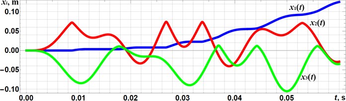
a)
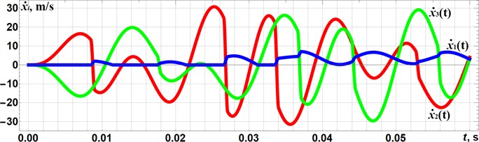
b)
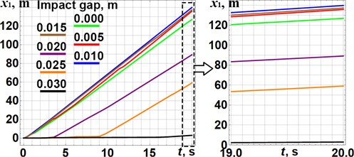
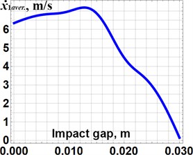
In order to check the correctness of the optimization technique considered above, let us adopt the distances , characterizing the corresponding impact gaps as the changeable parameters effecting the kinematic and dynamic characteristics of the vibro-impact system. Fig. 3 presents the dependencies of the wheeled platform displacements and average velocity on the impact gaps values ( 0.03 m). The optimization problem defining the system’s inertia-stiffness parameters (, , , ) was solved above for the values 0.01 m, 0.01 m. The obtained plots substantiate the maximal values of the wheeled platform average velocity of about 7 m/s in the impact gaps range 0.01 m 0.015 m.
Fig. 3Dependencies of the platform a) displacement and b) average velocity on the impact gaps values
a)
b)
5. Conclusions
The paper considers the improved design of the wheeled vibro-impact locomotion system (Fig. 1), which can be used for inspecting and cleaning the pipelines. It is equipped with the additional braking mechanisms that allows one-way rotation of the wheels. The vibrations are excited by the twin crank-slider mechanism setting two internal bodies into the translational oscillatory motion. Providing the vibro-impact operational conditions, the stepwise (discontinuous) translational motion of the wheeled platform is studied. The corresponding mathematical model describing the system motion conditions is developed, and the analysis of the basic stages of the internal bodies oscillations is carried out. The analytical solutions of the derived differential equations are presented for the first two stages of the internal bodies oscillations. Based on the obtained solutions, the system’s parameters optimization problem is stated and solved using the Mathematica software. The numerical modeling of the system locomotion allows for substantiating the correctness of the developed mathematical model and of the proposed parameters optimization technique. All the changes in the position of the wheeled platform are caused by the impacts of the internal masses (Fig. 2), and the maximal values of the wheeled platform average velocity of about 7 m/s are located in the impact gaps range 0.01 m 0.015 m (Fig. 3), which were initially used for solving the optimization problem. The increase in the impact gaps over 0.03 m causes the non-impact operational conditions characterized by the lowest values of the wheeled platform average velocity.
References
-
V.-D. Nguyen, K.-T. Ho, N.-T. La, Q.-H. Ngo, and K.-T. Nguyen, “An experimental study on the self-propelled locomotion system with anisotropic friction,” in Lecture Notes in Mechanical Engineering, Singapore: Springer Singapore, 2022, pp. 537–545, https://doi.org/10.1007/978-981-16-3239-6_40
-
K.-T. Nguyen, N.-T. La, K.-T. Ho, Q.-H. Ngo, N.-H. Chu, and V.-D. Nguyen, “The effect of friction on the vibro-impact locomotion system: modeling and dynamic response,” Meccanica, Vol. 56, No. 8, pp. 2121–2137, Aug. 2021, https://doi.org/10.1007/s11012-021-01348-w
-
Y. Yan, Y. Liu, J. Páez Chávez, F. Zonta, and A. Yusupov, “Proof-of-concept prototype development of the self-propelled capsule system for pipeline inspection,” Meccanica, Vol. 53, No. 8, pp. 1997–2012, Jun. 2018, https://doi.org/10.1007/s11012-017-0801-3
-
J. Xu and H. Fang, “Improving performance: recent progress on vibration-driven locomotion systems,” Nonlinear Dynamics, Vol. 98, No. 4, pp. 2651–2669, Dec. 2019, https://doi.org/10.1007/s11071-019-04982-y
-
B. Diao, X. Zhang, H. Fang, and J. Xu, “Bi-objective optimization for improving the locomotion performance of the vibration-driven robot,” Archive of Applied Mechanics, Vol. 91, No. 5, pp. 2073–2088, May 2021, https://doi.org/10.1007/s00419-020-01870-5
-
I. A. Loukanov, V. G. Vitliemov, and I. V. Ivanov, “Dynamics of a vibration-driven one-way moving wheeled robot,” IOSR Journal of Mechanical and Civil Engineering, Vol. 13, No. 3, pp. 14–22, 2016, https://doi.org/10.9790/1684-1303051422
-
I. A. Loukanov, V. G. Vitliemov, and I. V. Ivanov, “Dynamics of a mobile mechanical system with vibration propulsion (VibroBot),” International Journal of Engineering Research and General Science, Vol. 4, No. 6, pp. 2320–9364, Jul. 2016.
-
I. A. Loukanov, “Multi-criteria identification of VibroBot dynamic characteristics,” IOSR Journal of Engineering, Vol. 6, No. 7, pp. 26–35, Jul. 2016, https://doi.org/10.9790/3021-067012635
-
O. Lanets, O. Kachur, V. Korendiy, and V. Lozynskyy, “Controllable crank mechanism for exciting oscillations of vibratory equipment,” in Lecture Notes in Mechanical Engineering, Cham: Springer International Publishing, 2021, pp. 43–52, https://doi.org/10.1007/978-3-030-77823-1_5
-
V. Korendiy, V. Gursky, O. Kachur, V. Gurey, O. Havrylchenko, and O. Kotsiumbas, “Mathematical modeling of forced oscillations of semidefinite vibro-impact system sliding along rough horizontal surface,” Vibroengineering Procedia, Vol. 39, pp. 164–169, Dec. 2021, https://doi.org/10.21595/vp.2021.22298
-
V. Korendiy et al., “Kinematic and dynamic analysis of three-mass oscillatory system of vibro-impact plate compactor with crank excitation mechanism,” Vibroengineering Procedia, Vol. 40, pp. 14–19, Feb. 2022, https://doi.org/10.21595/vp.2022.22393
About this article

