Abstract
The landing gear plays a very important role during landing by absorbing the high impact energy of the aircraft. The main landing gear absorbs the bulk of the load to reduce the load experienced by both the aircraft fuselage and the nose landing gear. In this paper, a mathematical approach is used to extract the dynamic characteristics of the system. A two-degree of freedom mathematical model of the main landing gear is developed. This model is used to derive the dynamic equations of the landing gear system and to study the behaviour of main landing gear during main gear and nose gear touchdown conditions. The non-linear stiffness and damping co-efficient in an Oleo-Pneumatic shock absorber are integrated into the system to achieve a more accurate response of the system. The response of this system is established by adopting a complex modal analysis approach to account for the non-classical damping exhibited by the system. The obtained spring force, damping force and responses are reported. This work provides an alternative approach using complex modal analysis to obtain results for complex systems exhibiting non-linear characteristics.
1. Introduction
The landing gear ensures the aircraft lands safely, slows down and has a comfortable trip during taxi. This is achieved by absorbing high amount of impact load during landing. Therefore, landing gear system is one of the subsystems which is most crucial for an aircraft. Failure in absorption of these high loads would lead to catastrophic and fatal accidents. The ability to mathematically obtain response of the aircraft could greatly assist in optimizing and validating the performance of the shock absorber to improve its performance and increase its energy absorbing capacity.
Currey [1] discussed the basic principles and practices used in designing of a landing gear and concluded that the oleo-pneumatic landing gear is the most efficient landing gear. Carried out a discussion on the static and dynamic loading on the landing gear system and concluded that the main landing gear experiences the maximum load when compared to the nose landing gear. Daniels [2] experimented and modelled the main landing gear of Navy A6 Intruder aircraft, with the non-linear characteristics of the oleo-pneumatic shock absorber integrated into the model. Conclude that the results are in well agreement with the test data. Gehee et al., [3] used a computer program ACOLAG to predict the landing gear dynamics of airplane with passive and active main landing gear. Concluded, an active landing gear is more efficient than a passive landing gear. Gehee et al., [4] developed a mathematical model for an active controlled landing gear and demonstrated compute the loads during a vertical drop test. Computations are also carried out for a passive landing gear. Horta et al., [5] conducted an experiment on ground induced vibrations using an actively controlled landing gear of Navy A6 Intruder aircraft. Explained the basic control design for an active landing gear and formulated the flow rate equations into the landing gear from the controller. Wang et al., [6] developed a mathematical model to control aircrafts vibrations caused by runway excitations using an active landing gear system and controlled the vibrations using a Proportional Integral Derivative (PID) controller.
The shock absorber in an aircraft landing gear exhibits non-linear stiffness and damping parameters. Obtaining response for a system of this nature using conventional Modal analysis is difficult. Most of the works on dynamic characteristics of landing gear are based on simulation or an experimental approach. The novelty of the present work is to demonstrate the dynamic characteristic of the landing gear, incorporating the non-linear stiffness and damping parameters in the pneumatic shock absorber during touchdown duration using complex modal analysis. The nonlinear stiffness and damping parameters are derived and are integrated into the system. Computing code is created in MatLab and is used to extract the natural frequencies, Response, Spring Force and Damping Force of the system during landing.
2. Oleo pneumatic shock absorber
Fig. 1 shows a schematic diagram of an Oleo-Pneumatic shock absorber of an A6 intruder, used for the current study. The oleo pneumatic shock absorber consists of an upper chamber and a lower chamber of cross-sectional area A. Both the chambers are connected via an orifice of area . Most of the landing gear shock absorbers have a metering pin on the piston which partially covers the orifice area as the piston moves up, this mechanism has been ignored in this analysis. The upper chamber is partially filled with nitrogen, while the rest of the upper and lower chambers are filled with hydraulic fluid [6]. During the landing procedure, the bulk of the impact load is taken by the main landing gear while the nose landing gear takes 10-15 % of the load [1]. The remaining 85-90 % of the load is absorbed by the main landing gear. The huge impact loads need to be damped by the shock absorbers in the main landing gear system.
In the Oleo-Pneumatic shock absorber the spring and damping characteristics are achieved by the gas and the hydraulic fluids in the system respectively. The spring action is provided by the gas during compression and the damping effect is achieved by the hydraulic fluid moving from one chamber to another through the orifice. The system strongly exhibits non-linear characteristics, resulting in a more accurate behaviour of the system.
3. Mathematical model
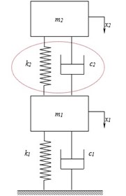
The aircraft with main landing gear system is modelled as a two degree of freedom system [6] and is shown in Fig. 2. The mass of the landing gear piston and tyre is represented by and partial mass of the aircraft and the landing gear cylinder is represented by . The stiffness and damping co-efficient of the tyre are represented by and respectively. Gas spring stiffness [7] and damping co-efficient of the shock strut is represented by and respectively.
Fig. 1Schematic diagram of an oleo pneumatic shock strut
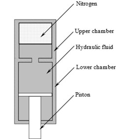
Fig. 2Two degree of freedom an aircraft system
The equation of motion of the system can be written in matrix form as:
Which can be further represented as:
The mass, damping and stiffness matrices are represented as , , respectively. In modal analysis, the system is classically damped. When a system is classically damped the (the symbol represents Eigen vector matrix) is a diagonal matrix. Due to the shock absorber exhibiting non-linear stiffness and damping parameters, the system is non-classically damped. When a system is non-classically damped, is not a diagonal matrix. Conventional modal approach cannot be used in this scenario. Complex modal analysis is used to obtain natural frequencies, damping ratios and modal vectors, Eq. (2) can be written as two sets of first order differential equations [9], as follows:
The solution of the Eq. (3) is given as follows:
A non-linear characteristic of gas stiffness () of the system is represented [7] as:
Using mass conservation law and Bernoulli’s equation the damping force is considered [6] as:
The non-linear damping co-efficient () is obtained as:
Using Eqn. (5) and (7), in Eqn. (3) and further evaluating, the response of the mass and are obtained. The various properties of the system are tabulated in Table 1 and are used to calculate the response of the aircraft during landing.
4. Results and discussion
Fig. 3 shows the variation of strut length with time for an aircraft landing in a downhill runway at a sink rate of 5 m/s [3]. Strut stroke variations are used to calculate the stiffness and damping co-efficient of the system.
Table 1The parameter values used in the simulation [5, 6]
Landing gear parameter/properties | Representation | Dimensions | Units |
Mass of the tyre and the piston | 145.1 | Kg | |
Partial mass of the aircraft | 4832.7 | Kg | |
Stiffness of the tyre | 1.5×10⁶ | Nm-1 | |
Damping co-efficient of the tyre | 2.6×10⁶ | Ns/m-1 | |
Area of the orifice | 6.412×10⁻⁴ | m2 | |
Area of the shock strut cylinder | 1.376×10⁻² | m2 | |
Discharge co-efficient of orifice | 0.3 | ||
Pressure inside the shock strut | 1.6×10⁶ | Pa | |
Adiabatic gas constant of the nitrogen | 1.4 | ||
Length of the shock strut | 0.38 | m | |
Density of the hydraulic fluid | 912 | Kg/m3 |
The variation of the strut length leads to non-linearity in stiffness and damping of the system. This in turn results in the non-linear variation of the stiffness and damping forces. The variation of spring force and damping force time are shown in Fig. 4 and Fig. 5. It can be observed that with an increase in stroke length the stiffness and the spring force of the shock absorber also increases. Similarly, the damping force of the system increases with an increase in rate of change of strut length of the shock absorber.
Fig. 3Strut stroke variation with time
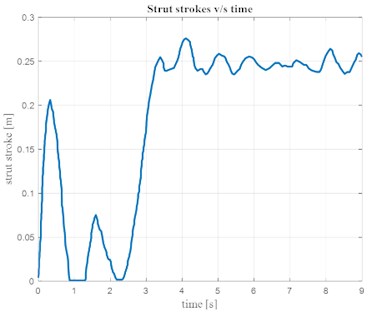
Fig. 4Variation of spring force with time
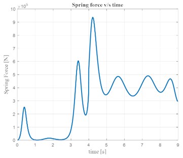
Fig. 5Variation of damping force with time
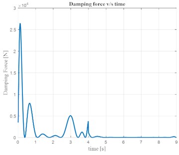
Fig. 6 shows the response of the aircraft for the duration between the main landing gear touch down at 0 sec to the nose gear touch down at 3.8 sec.
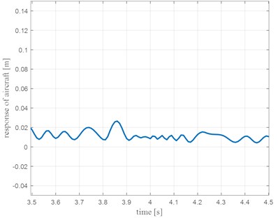
Fig. 7 shows the magnified response portion of Fig. 6 for time between 0 and 1 s and Fig. 8 shows the magnified response portion of Fig. 6 for time between 3.5 and 4.5 s.
Fig. 6Response of aircraft (m2) v/s time
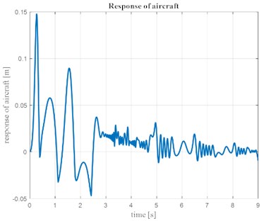
Fig. 7Response of aircraft (m2) at main gear touchdown
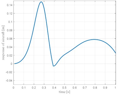
Fig. 8Response of Aircraft (m2) at nose gear touchdown
5. Conclusions
The response of an aircraft during landing is one of the key factors in designing a safe and optimal shock absorber. The current work explores an analytical approach in solving the non-linear characteristics of an aircraft landing gear system. A mathematical approach for finding responses of a non-linear system could greatly help in validation of simulations for future works and not totally rely on experimentation which is an expensive and a time consuming alternative. This can also aid in further optimising the shock absorber, significantly increasing the life of the landing gear and reduce the loads experienced by the fuselage of the aircraft.
References
-
Currey Norman S. Aircraft Landing Gear Design: Principles and Practices. American Institute of Aeronautics and Astronautics (AIAA) education series, 1998.
-
Daniels James N. A Method for Landing Gear Modeling and Simulation with Experimental Validation. NASA CR-2011601, 1996.
-
McGehee John R., Carden Huey D. Analytical Investigation of the Landing Dynamics of a Large Airplane with a Load Control System in the Main Landing Gear. NASA Technical Paper 1555, 1979.
-
McGehee John R., Carden Huey D. A Mathematical Model of an Active Control Landing Gear for Load Control during Impact and Roll-Out. NASA TN D-8080, 1976.
-
Horta Lucas G., Daugherty Robert H., Martinson Veloria J. Modeling and Validation of a Navy A6-Intruder Actively Controlled Landing Gear System. NASA/TP-1999-209124, 1999.
-
Wang Haitao, Xing J. T., Pricea W. G., Li Weiji An investigation of active landing gear system to reduce aircraft vibrations caused by landing impacts and run way excitations. Journal of Sound and Vibration, Vol. 317, Issues 1-2, 2008, p. 50-66.
-
Savaresi S. M., Poussot Vassal C., Spelta C., Sename O., Dugard L. Semi Active Suspension Control Design for Vehicles. Elsevier, 2010.
-
Vasta Marcello Classically and Non-Classically Damped Multi Degree of Freedom Structural Systems, Dynamic Response Characteristics. Encyclopedia of Earthquake Engineering, Springer-Verlag Berlin Heidelberg, 2014.
-
Adhikari S., Phani S. A. Rayleigh’s classical damping revisited. International Conference on Civil Engineering in the New Millennium: Opportunities and Challenges, 2007.
About this article

