Abstract
The thorough analysis of the technological processes used to purify the wastewater from food and processing enterprises (bakery, brewery, coffee, sugar, beverage, etc.) has established that among the most effective processes are the physical ones. From the wide range of physical methods of wastewater treatment, the cavitation treatment methods are of the most promising from the viewpoint of industrial application. The present paper considers an enhanced design of a low-frequency vibratory cavitation device with an electromagnetic drive. Unlike many other cavitators of ultrasonic or hydrodynamic action, the proposed vibratory cavitation device can treat the wastewater in a continuous liquid flow, has no rotating components and parts, which significantly increases its reliability and durability, and can be equipped with changeable concaves (grates) depending on the pollutants to be purified. The research methodology consists of two main stages: development of the dynamic diagram and mathematical model of the considered cavitation device; numerical simulation of the working members vibrations at different operational conditions. The obtained results are presented in the form of time dependencies of the concaves (grates) displacements, speeds, and accelerations under various viscous friction and excitation parameters. The main scientific novelty of this study, in addition to the improved design of the vibratory cavitator, is considering the influence of the changeable electromagnetic excitation force and viscous friction force on the dynamic behavior of the concaves (grates). Further investigations on the present topic can be focused on the practical implementation and experimental testing of the proposed cavitation device in order to increase the water purification degree.
Highlights
- The paper considers an enhanced design of a low-frequency vibratory cavitation device with the electromagnetic drive and changeable concaves intended for wastewater purification in a continuous flow.
- The dynamic diagram of the cavitator’s oscillatory system is developed; the corresponding mathematical model is derived. The cavitator operational peculiarities are analyzed at different conditions.
- The obtained results may be used while improving the existent designs of electromagnetically driven vibratory cavitation devices and while developing novel technologies of wastewater purification.
1. Introduction
The current intensification of production processes in all areas of economic activity, without exception, has inevitably led to a rapid increase in the volume of harmful emissions into the atmosphere and wastewater from enterprises and utilities. Increasing wastewater pollution has an extremely negative impact on the ecological state of the environment [1, 2] and on the vital activity of people, flora, and fauna [3]. While mechanical impurities in wastewater are quite successfully treated by waste liquid lagoons [2], and chemical pollutants are countered by methods of their chemical neutralization [3], organic pollutants are extremely difficult to deal with [4]. Dissolved in water at the level of molecular interaction, organic contaminants precipitate, if at all, only after a very long settling period [5]. The effect of chemical reagents on them is virtually unacceptable due to possible contamination of water, which, after treatment, necessarily enters the environment [6]. Existing physical methods of water purification, such as electric spark discharges [7], magnetic fields [8, 9], etc. are undoubtedly effective but extremely energy-intensive. This limits their use for the treatment of large volumes of organically contaminated wastewater.
Hydrodynamic cavitation, although inferior in intensity to ultrasonic cavitation, has a wider industrial and domestic application [5]. For example, hydrodynamic cavitation can be effectively implemented for the treatment of wastewater from food and processing enterprises, water parks and swimming pools [10, 11], etc. However, a significant obstacle to the widespread use of hydrodynamic cavitation for the cleaning treatment (purification) of wastewater or natural water is the lack of industrial high-performance cavitation equipment. This problem has not lost its relevance, and its solution will not only reduce the costs of enterprises for treatment processes but also significantly decrease the pollution intensity and improve the ecological state of the environment [12, 13]. Therefore, the search for effective methods of purification (cleaning) of wastewater contaminated with organic matter remains relevant at the present time. And one of the most important problems currently set for engineers and researchers is developing relatively simple in design and high-performance devices for the cavitation treatment of various liquids.
The present research is based on the authors’ previous investigations in the fields of vibratory technological equipment [14, 15] and hydrodynamic cavitation devices [16, 17]. The paper combines the authors’ experience in the field of creating a vibratory system able to provide wastewater purification due to generating the cavitation processes. The main objective of this study is to develop an enhanced design of an efficient low-frequency vibratory cavitation device for cleaning treatment (purification) of wastewater of food and processing enterprises from organic and biological pollutants (contaminants). In addition, the numerical modeling of the working members (concaves, grates) vibrations at different operational conditions is to be performed in order to study the influence of the changeable electromagnetic excitation force and viscous friction force on the dynamic behavior of the cavitator’s vibratory system.
2. Research methodology
2.1. Design peculiarities of an enhanced low-frequency vibratory cavitation device
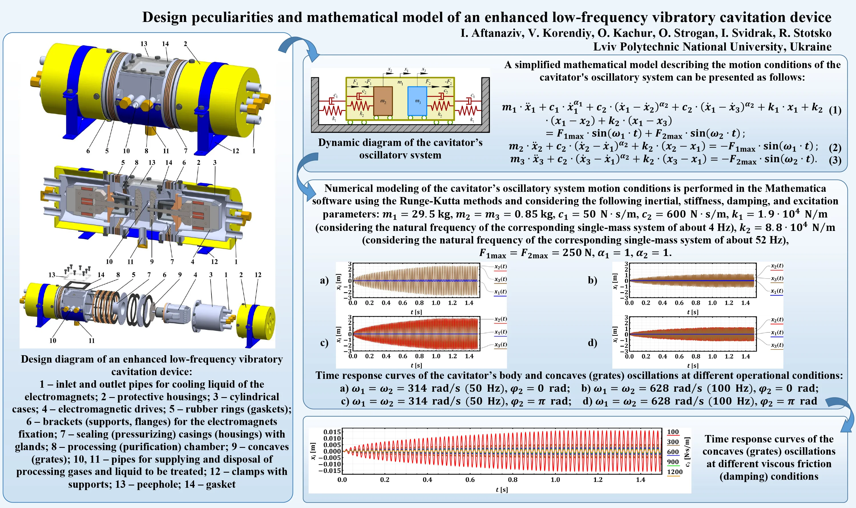
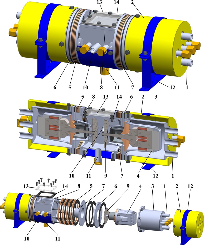
Most of the existent vibratory cavitation devices are restricted to operate at the temperatures higher than 70 °C and pressure of over 0.1 MPa [5, 10, 11, 16, 17]. In Fig. 1, there is presented the design diagram of the enhanced low-frequency vibratory cavitation device equipped with the electromagnetic drive for purifying liquids at the pressure of 0.35…0.4 MPa and temperature over 75…80 °C. The main unit of the proposed cavitator is the processing (purification) chamber 8 with two symmetrical brackets (flanges) 6, to which two cylindrical cases 3 equipped with the inlet pipes 1 for supplying the cooling liquid are connected. Inside each case 3, there are installed the stators with coils and the armatures of the electromagnetic drives 4. The drives are sealed from the working chamber with the help of the rubber rings (gaskets) 5 and sealing (pressurizing) casings (housings) 7 designed with central holes and glands for moving the armature rods of the electromagnets 4. The cylindrical cases 3 are sealed using the gaskets placed between the cases 3 and the corresponding brackets (flanges) 6. The armature rod is fixed to the disk-type spring element (rubber membrane) at its central hole. The membrane allows the armature rod to oscillate at the amplitude of 3.5…4 mm. The initial distance between the armature and the core of the electromagnet can be regulated by the number of washers (spacers) installed between the armature body and the disk-type spring element (rubber membrane). On the ends of the armature rods, there are fixed the concaves (grates) 9 for generating cavitation. The flat or conical surface of a concave is made with a system of holes ensuring the liquid flows through. The working chamber is equipped with the pipes 10 and 11 for supplying and disposal of the processing gases (nitrogen, air, etc.) and liquid to be treated. Considering the safety regulations, the cavitator is covered by the protective housings 2, which are fixed in the supports 12 with the help of clamps. The supports are mounted on the base through the rubber dampers. In addition, the working chamber 8 is equipped with the peephole (observing window) 13 bolted to the chamber through the gasket 14.
The best performance of the vibratory cavitation-purification process is observed at the near-resonance regimes when the forced frequency of the electromagnetic exciter is close to the natural frequency of the cavitator’s oscillatory systems under the predefined operational conditions (liquid type, pressure, and temperature). These regimes can be experimentally tested by adjusting the forced frequency and the oscillation amplitude of the armature rods in a wide range with the help of a special control system. The system allows for adjusting the excitation conditions in accordance with technological requirements and with the aim of providing the best performance of the cavitation-purification process or minimal power consumption of the electromagnetic drive.
Fig. 1Design diagram of an enhanced low-frequency vibratory cavitation device: 1 – inlet and outlet pipes for cooling liquid of the electromagnets; 2 – protective housings; 3 – cylindrical cases; 4 – electromagnetic drives; 5 – rubber rings (gaskets); 6 – brackets (supports, flanges) for the electromagnets fixation; 7 – sealing (pressurizing) casings (housings) with glands; 8 – processing (purification) chamber; 9 – concaves (grates); 10, 11 – pipes for supplying and disposal of processing gases and liquid to be treated; 12 – clamps with supports; 13 – peephole; 14 – gasket
2.2. Dynamic diagram and mathematical model of the cavitator’s oscillatory system
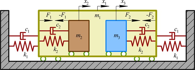
The dynamic diagram of the cavitator’s oscillatory system is presented in Fig. 2. The external moving body (mass ) simulates the cavitator suspended from the stationary base by the system of spring-damper elements characterized by the stiffness and damping coefficients , , respectively. The internal oscillating bodies (masses , ) are set into motion due to the action of the forces and applied between the corresponding masses and the cavitator’s body (see Fig. 2). The internal bodies can slide along the horizontal longitudinal axis of the cavitator and their motion is restricted by the spring-damper elements characterized by the stiffness and damping coefficients , , respectively. In order to uniquely describe the motion conditions of the cavitator’s oscillatory system, the following generalized coordinated are adopted: , , – absolute displacements of the cavitator’s body (mass ) and internal masses (, ) in the inertial coordinate system (relative to the stationary base, see Fig. 2).
While performing further investigations, the pull-push forces of the electromagnets are considered as periodic ones: , , where , are the maximal (amplitude) values of the excitation forces; , are the forced frequencies; , are the initial phases. Neglecting the complicated hydrodynamic processes occurring during the cavitation processes, let us consider the simplified case when the damping (viscous friction) forces are approximately modeled as functions of the cavitator’s body absolute speed and concaves (grates) relative speeds: , , , where , are the correction coefficients depending on the liquid to be purified. According to Hooke’s law, the spring forces are considered as functions of the cavitator’s body absolute displacement and concaves relative displacements: , , . Therefore, the simplified mathematical model describing the motion conditions of the cavitator’s oscillatory system can be presented as follows:
Fig. 2Dynamic diagram of the cavitator’s oscillatory system
3. Results and discussion
3.1. Studying the influence of the excitation frequency on the system’s dynamic behavior
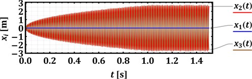
Numerical modeling of the cavitator’s oscillatory system motion conditions is performed in the Mathematica software using the Runge-Kutta methods and considering the following inertial, stiffness, damping, and excitation parameters [10, 11, 16, 17]: 29.5 kg, 0.85 kg, 50 (N∙s)/m, 600 (N∙s)/m, 1.9∙104 N/m (considering the natural frequency of the corresponding single-mass system of about 4 Hz), 8.8∙104 N/m (considering the natural frequency of the corresponding single-mass system of about 52 Hz), 250 N, , . The forced frequencies , and initial phases , of the electromagnetic excitation are considered as controllable parameters. The following cases are studied in the present paper: 314, 628 rad/s (50, 100 Hz); 0; 0, rad. The corresponding results of the numerical modeling are presented in Fig. 3 in the form of time dependencies of the cavitator’s body and armature rods displacements. The amplitudes of vibrations (, ) decrease from about 2.8 mm to 1.2 mm with an increase in the forced frequency from 50 Hz to 100 Hz. Therefore, the proposed low-frequency operational conditions of an enhanced device allow for generating larger displacements of the concaves (grates) and for intensifying the cavitation and purification process. In order to provide the same amplitudes of concaves at larger forced frequencies, it is necessary to equip the device with a more powerful electromagnetic drive reducing the machine’s efficiency due to larger power consumption.
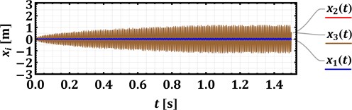
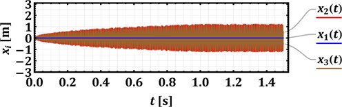
In order to reduce vibrations that can be transmitted from the oscillating parts of the cavitator to the supports and nearby equipment, the armature rods of the actuating electromagnets should be subjected to synchronous antiphase oscillations (, rad). This can be achieved by the corresponding connection of the stators’ coils of the electromagnets to the power supply and control system. Herewith, the reactive forces generated due to oscillatory movements of both armatures, being synchronous and oppositely directed, mutually cancel each other and minimize the transmission of vibrations to the machine’s base.
Fig. 3Time response curves of the cavitator’s body and concaves (grates) oscillations at different operational conditions
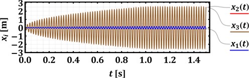
a) 314 rad/s (50 Hz), 0 rad
c) 314 rad/s (50 Hz), rad
b) 628 rad/s (100 Hz), 0 rad
d) 628 rad/s (100 Hz), rad
3.2. Analyzing the influence of the viscous friction on the system’s vibrations
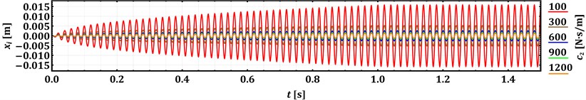
In order to analyze the cavitator’s operation while purifying different liquids, the influence of the viscous friction (damping) coefficient on the concaves (grates) motion conditions is analyzed. The input parameters are the same as considered above. The forced frequency is set to 314 rad/s (50 Hz), and the phase shift angle rad. The numerical modeling is performed at the following values of 100, 300, 600, 900, 1200 (N∙s)/m. The decrease in the from 1200 to 100 (N∙s)/m causes a rapid increase in the concaves (grates) amplitude. Therefore, in order to ensure the safe and reliable operation of the cavitator, its control system should provide the possibility of regulating the forced frequency and the voltage supplied to the electromagnets.
Fig. 4Time response curves of the concaves (grates) oscillations at different viscous friction (damping) conditions
4. Conclusions
The paper considers the enhanced design of the low-frequency vibratory cavitation device with an electromagnetic drive intended for wastewater purification. The proposed cavitator can treat the liquids in a continuous flow and can be equipped with changeable concaves (grates) depending on the pollutants to be purified. The dynamic diagram of the cavitator’s oscillatory system is developed, and the mathematical model describing its dynamic behavior is derived. The cavitator’s operational peculiarities are thoroughly analyzed at different operational conditions (forced frequencies and viscous friction factors). The obtained results may be used while improving the existent designs of the electromagnetically driven vibratory cavitation devices and while developing novel technologies of wastewater purification based on the hydrodynamic cavitation techniques. Further investigations on the subject of the present research can be focused on the practical implementation and experimental investigation of the developed cavitation device in order to maximize its water purification degree and reduce power consumption.
References
-
O. Rylsky, K. Dombrovskiy, Y. Masikevych, A. Masikevych, and M. Malovanyy, “Evaluation of water quality of the Siret River by zooperiphyton organisms,” Journal of Ecological Engineering, Vol. 24, No. 6, pp. 294–302, Jun. 2023, https://doi.org/10.12911/22998993/163166
-
C. Santulli, C. Fragassa, A. Pavlovic, and D. Nikolic, “Use of sea waste to enhance sustainability in composite materials: A review,” Journal of Marine Science and Engineering, Vol. 11, No. 4, p. 855, Apr. 2023, https://doi.org/10.3390/jmse11040855
-
R. Zait, D. Fighir, B. Sluser, O. Plavan, and C. Teodosiu, “Priority pollutants effects on aquatic ecosystems evaluated through ecotoxicity, impact, and risk assessments,” Water, Vol. 14, No. 20, p. 3237, Oct. 2022, https://doi.org/10.3390/w14203237
-
L. Wang et al., “Bibliometric analysis and literature review of ultrasound-assisted degradation of organic pollutants,” Science of The Total Environment, Vol. 876, p. 162551, Jun. 2023, https://doi.org/10.1016/j.scitotenv.2023.162551
-
M. Gągol, A. Przyjazny, and G. Boczkaj, “Wastewater treatment by means of advanced oxidation processes based on cavitation – A review,” Chemical Engineering Journal, Vol. 338, pp. 599–627, Apr. 2018, https://doi.org/10.1016/j.cej.2018.01.049
-
A. Saravanan et al., “Effective water/wastewater treatment methodologies for toxic pollutants removal: Processes and applications towards sustainable development,” Chemosphere, Vol. 280, p. 130595, Oct. 2021, https://doi.org/10.1016/j.chemosphere.2021.130595
-
O. Petrov, S. Petrichenko, A. Yushchishina, O. Mitryasova, and V. Pohrebennyk, “Electrospark method in galvanic wastewater treatment for heavy metal removal,” Applied Sciences, Vol. 10, No. 15, p. 5148, Jul. 2020, https://doi.org/10.3390/app10155148
-
X. Liu et al., “Investigation of the effect of sustainable magnetic treatment on the microbiological communities in drinking water,” Environmental Research, Vol. 213, p. 113638, Oct. 2022, https://doi.org/10.1016/j.envres.2022.113638
-
N. Syamimi Zaidi et al., “Insights into the potential application of magnetic field in controlling sludge bulking and foaming: A review,” Bioresource Technology, Vol. 358, p. 127416, Aug. 2022, https://doi.org/10.1016/j.biortech.2022.127416
-
L. Shevchuk, I. Aftanaziv, L. Strutynska, O. Strogan, and I. Samsin, “Identification of special features in the electrolysis-cavitation water treatment in pools,” Eastern-European Journal of Enterprise Technologies, Vol. 2, No. 10 (98), pp. 6–15, Apr. 2019, https://doi.org/10.15587/1729-4061.2019.162229
-
I. Aftanaziv, L. Shevchuk, M. Malovanyy, L. Strutynska, and I. Samsin, “Cavitation-reagent technology for water purification of pools and water parks,” Journal of Ecological Engineering, Vol. 20, No. 6, pp. 141–152, Jun. 2019, https://doi.org/10.12911/22998993/108638
-
Y. Chen, C. Yin, and Y. Song, “Application of hydrodynamic cavitation in the field of water treatment,” Chemical Papers, Vol. 77, No. 7, pp. 3521–3546, Jul. 2023, https://doi.org/10.1007/s11696-023-02754-y
-
A. V. Mohod, A. C. S. C. Teixeira, M. V. Bagal, P. R. Gogate, and R. Giudici, “Degradation of organic pollutants from wastewater using hydrodynamic cavitation: A review,” Journal of Environmental Chemical Engineering, Vol. 11, No. 3, p. 109773, Jun. 2023, https://doi.org/10.1016/j.jece.2023.109773
-
Y. Kharchenko et al., “Nanostructural changes in a Ni/NiO cermet during high-temperature reduction and reoxidation,” Springer Proceedings in Physics, Vol. 246, pp. 219–229, 2021, https://doi.org/10.1007/978-3-030-51905-6_17
-
V. Borovets, O. Lanets, V. Korendiy, and P. Dmyterko, “Volumetric vibration treatment of machine parts fixed in rotary devices,” in Lecture Notes in Mechanical Engineering, pp. 373–383, 2021, https://doi.org/10.1007/978-3-030-68014-5_37
-
V. V. Nykyforov, M. S. Malovanyy, I. S. Aftanaziv, L. I. Shevchuk, and L. R. Strutynska, “Developing a technology for treating blue-green algae biomass using vibro-resonance cavitators,” Naukovyi Visnyk Natsionalnoho Hirnychoho Universytetu, Vol. 2019, No. 6, pp. 181–188, Dec. 2019, https://doi.org/10.29202/nvngu/2019-6/27
-
I. Aftanaziv, M. Malovanyy, L. Shevchuk, O. Strogan, and L. Strutynska, “Economic and environmental benefits of using cavitation treated fuel in vehicles of internal combustion engines,” Communications – Scientific letters of the University of Zilina, Vol. 24, No. 3, pp. B158–B169, Jul. 2022, https://doi.org/10.26552/com.c.2022.3.b158-b169
About this article

The authors have not disclosed any funding.
The datasets generated during and/or analyzed during the current study are available from the corresponding author on reasonable request.
The authors declare that they have no conflict of interest.
