Abstract
The article describes the method for studying the dynamics of the cutting tool in the processing of deep holes. Instead of the classic second-order differential equation, two first-order equations introduced. These equations relate the angular acceleration and angular velocity with the shear stress.
1. Introduction
One of the most popular ways of handling workpieces is machining holes. Deep-hole making by means gundrill, reamers refers to a most complicated process operations. Here it is necessary select speed of movement of a tool nose. Considering physical and chemical processes it is necessary to estimate interaction with a surface of a detail. During drilling there are various dynamic phenomena. They have a negative impact on tool functionality and quality of holes. Therefore, the scientific study of the process of deep drilling is an urgent task.
1.1. Peculiarities of deep holes drilling
The complexity of process in the processing of deep holes ( 5) is caused presence of the long mechanical line (rod, drill pipe), which perceives axial, torsion and bending loadings. One of the schemes of such a process is shown in Fig. 1. Here, the tool comprising a cutting head 1 fixed on the thread of the drill tube 2 is placed in a work spindle 3. The tool performs both rotation and forward motion.
Fig. 1Deep hole machining scheme: 1 – cutting part with cutting and support plates, 2 – drilling pipe, 3 – work spindle, 4 – aligning bushing, 5 – machine support stand, 6 – machined part
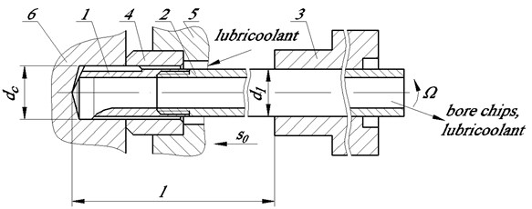
At the beginning of work of the machine the axis of guide bushing 4 and a coordinate axis of the hole of detail 6 should coincide. After this successively include the supply of coolant, spindle rotation and axial feed . Coolant lubricates, cools and moves the bore chips to the inner channel of the drilling pipe, and then falls in cuttings pit. This raises the problem of the functioning of the cutting part, which is removed from a spindle. Drilling process is complicated by the uneven rotation, variable elasticity line, variable rotational moment and cutting force, precession oscillation of axis of rotation and longitudinal oscillations of the cutting part. This leads to faceting, to significant deviations, to loss of dimensional accuracy and so on [1-3].
All methods of deep drilling, in varying degrees, are characterized by the following features:
– the cutting part is removed (sometimes considerably) from a spindle;
– supporting components of head tool glide over the surface of the machined holes;
– bore chips from a zone of cutting delete a stream of a lubricoolant.
In this connection, there is a need to complement the modern theory of deephole machining. This theory together should cover a significant range of issues such as cutting, heat transfer, dynamics, residual stresses, and others. We will focus on the dynamic aspect of the drilling process. In recent years, a series of works that develop understanding of the dynamic processes at deephole machining [4-11]. It is related to growing need of mechanical engineering in manufacture of qualitative bore. A lot of published works describe the separate issues, and disregarding influence of one or another factor. This we can explain frequent necessity of carrying out of experiments by selection of cutting modes even at minor change of process parameters.
However, here too, there are unstudied issues, related to formation and removal of chip from hole, correlation between torsion and longitudinal fluctuations of cutting part, stem deformations and etc.
So, for example, in order to determine the stresses at tool cutting edges we usually use the known equations, obtained as a result of approximation of experimental data, where the given variables are directly the parameters of cutting (cutting depth, supply, finished dimensions) [12]. Such approach shall cannot be used for manufacturing technology of deep holes, as far as the difficulty of deephole machining process is stipulated by presence of long mechanical main line, conceiving the axial, torsion and bending loads. Hence, there is a necessity in carrying out of comprehensive analysis of all force factors and further mathematical formalization of cutting process. This aspect is described in the next chapter of the article.
1.2. Theoretical aspect of interaction dynamics of tool with part surface
In the process of drilling the quality of cutting process is also affected by motion speed of cutting part of tool head, normal and shear stresses in the cross-sections of drilling pipe (rod, pipe column).
In mechanics for descriptions of torsion vibrations differential equation is usually applied in partial derivatives [13]:
where – cross section angular displacement; – time; – shear modulus; – material density – longitudinal coordinate.
As a result, this equation relates the displacements of the input and output coordinates. However, it is more convenient to study this process using another method [14], where not only the displacement, but also the stress, is considered in the line (rod). Such approach gives the possibility to investigate the dynamic phenomena on the basis of methods of automatic control theory with usage of principal model of inertial disc, rotating at the end of rod. The issue is described in the research works [14-16].
From equation moment of momentum in differential from [13] we can obtain the equation [14]:
where – speed rotation of bar cross-section displacements, ; – rod radius; – maximum shear stress in rod cross-section.
Comparing Eqs. (1) and (2) we get the expression:
which after integration with respect to and differentiation with respect to , is reduced to the form:
The system of Eqs. (3), (4) allows to describe changes of stresses and velocities of motion elementary sections of rod. Without review of viscous friction loss and on the assumption that density and shear modulus are constant, the given equations can be written in Laplace transforms:
Having differentiated Eq. (5) by , then excluding by means of Eq. (6) derivative we receive the new differential equation of second order with constant coefficients:
where – new variable:
Its solution has the following view:
Constant integrations , shall be determined by edge conditions at 0:
Then, considering Eqs. (10), (11), we obtain:
After substitution of these dependences in Eq. (9) and introduction of hyperbolic functions the solution shall be as follows:
Having solved the system of Eqs. (5) and (6) thus relatively we obtain:
Coefficient is operator coefficient of the waves propagation.
Assume that the final length of the line is l. Suppose also that the moment of momentum applied to the drill tube is fully consumed in the load. Taking this into account, we supplement the system of these equations with the following boundary conditions:
where – moment of resistance at the outlet end of the pipe with length ; , – rotational speeds of input and output pipe ends; , – maximum shear stress on the correspond ends of drilling tube; – coefficient of friction losses; – geometrical polar moment of pipe cross section resistance, adjoining to cutting head; – moment of cutting head inertia, adduced to the driven end of the pipe end.
From the joint algebraic solution Eqs. (13)-(15) we obtain:
where – function of torsion elasticity:
Eqs. (16), (17) make it possible to calculate the frequency characteristics of the drive. This allows us to determine the reaction of the drive to the harmonic variation in the speed of the driving link or the moment of resistance acting on the head of the tool with the coordinated load, when the moment of momentum brought to system completely is spent in working load.
For example, thus for 0, we obtain the frequency response , which illustrates the influence of the moment of resistance () on the speed of rotation of the cutting tool part (), and the frequency response , which illustrates the influence of its) to shear stresses ().
In the course of the transformations we have obtained a new complex function with the Laplacian (). Let us show under what conditions it becomes real function.
Assuming , where – frequency of harmonic vibrations; – imaginary unit. We reduce the function to the view:
From Eq. (19) it follows, that real variables are and :
In addition, the function torsion elasticity () is a real, but depending on the frequency of oscillations and parameters of the line.
Function characterizes the degree of distribution of rod parameters, – the properties of power trunk configuration. Dependency graph of functions is given in Fig. 2. From him is seen this that, as tends to zero, the function tends to unity: 0, 1. When changing in intervals , function takes negative values: 0. Here 0, 1, 2,..., .
When the deep holes drilling parameter does not exceed unity, then analysis shall be carried over for the case of elastic systems with lumped parameters [3]. Otherwise, it is necessary to take into account the distribution of parameters of the elastic line.
When , then Eq. (16) is reduced to the known equation, describing dynamic processes in actuator with short lines:
On the basis of the above method, frequency characteristics have been calculated, given in Fig. 3, for drill bit ВТА (Boring and Trepanning Association) with diameter of 16,3 mm at length of force sector of drilling pipe is 1000 mm, at outward diameter 15 mm, at wall thickness 1,5 mm, at torsion elasticity 4,26×10⁻⁶ [Нmm]-1, at moment of cutting head inertia 3,09×10⁻³ [Nmmsec2]; at friction loss coefficient 1 Nmmsek.
Fig. 2Change of function Zk from non-dimensional parameter αk
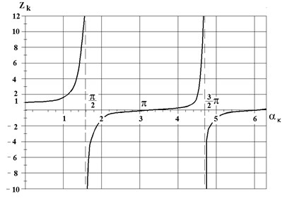
Fig. 3Frequency characteristics of drill bit ВТА: а) phase-frequency characteristics; b) amplitude frequency characteristics
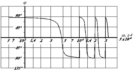
а)
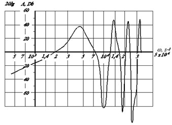
b)
It can be seen, that mechanical actuator, including spindle, drilling pipe, cutting part, from time to time go into resonance modes at frequencies 4396; 13330; 22510;… s-1. The number of such modes, as in usual elastic system, is endless [17].
2. Conclusions
An equation is obtained in Laplace images of the rotational motion of the cutting part of a drill with a long rod. The frequency characteristics of the instrument are calculated. The presented results enable choosing rational operating modes.
References
-
Terekhov V. M., Kondratenko L. A., Mironova L. I. Some dynamic features of interaction the cutting part of the gun drill with the detail. Mechanical Engineering and Automation Problems, Vol. 4, 2016, p. 78-84, (in Russian).
-
Terekhov V. M., Kondratenko L. A. About mathematical model of the process of deephole machining. Machinery Manufacture and Reliability, Vol. 1, 1999, p. 55-61, (in Russian).
-
Kondratenko L. A. Vibrations and Speed Regulation Methods of Movement of Technological Objects. MRSU, Moscow, 2005, (in Russian).
-
Messaound Amor, Weihs Claus Monitoring a deep hole drilling process by nonlinear time series modeling. Journal of Sound and Vibration, Vol. 326, Issues 3-5, 2009, p. 620-630.
-
Kondratyuk O. A. The stability of a deep hole drilling process using small unit-built machines. Equipment and Tools for Professionals, Vol. 6, 2005, p. 22-23, (in Russian).
-
Lakirev Deryabin S. G. I. P. Simulation of a hole machining using gun drills and reamers. IIRPC Snezhinsk and Science, SFTI, 2000, p. 107-108, (in Russian).
-
Yefimovich I. A. Dynamics of cutting forces during penetration. Herald of Mechanical Engineering, Vol. 2, 2003, p. 45-47, (in Russian).
-
Astakhov V. Gundrilling know-how gutt. Tool Engineering, Vol. 53, Issue 12, 2001, p. 34-38.
-
Weinert K., Peters C., Wittkop S. Finite Elemente optimieren lange. Bohrer Technika, Vol. 9, 2004, p. 8-12.
-
Mustafa Günay, Ulvi Seker, Gökhan Sur Design and construction of a dynamometer to evaluate the influence of cutting tool rake angle on cutting forces. Materials and Design, Vol. 27, 2006, p. 1097-1110.
-
Ee K. C., Dillon Jr O. W., Jawahir I. S. Finite element modeling of residual stresses in machining induced by cutting using a tool with finite edge radius. International Journal of Mechanical Sciences, Vol. 47, Issue 5, 2005, p. 1611-1628.
-
Granovsky G. I., Granovsky V. G. Metal Cutting. The Higher School, Moscow, 1985, (in Russian).
-
Sedov L. I. Continuum Mechanics. Nedra, Moscow, Vols. 1-2, 1970, (in Russian).
-
Kondratenko L. A. Calculation of Movement Speed Variations and Stresses in Machine Assemblies and Components. Sputnik, Moscow, 2008. (in Russian).
-
Kondratenko L., Terekhov V., Mironova L. The aspects of roll-forming process dynamics. 22 nd International Conference on Vibroengineering, Vibroengineering Procedia, Moscow, 2016, p. 460-465.
-
Kondratenko L. A., Terekhov V. M., Mironova L. I. About one method of research torsional vibrations of the core and his application in technologies of mechanical engineering. Journal of Engineering and Automation Problems. Vol. 1, 2017, p. 133-137, (in Russian).
-
Babakov I. M. Theory of Vibrations. GTTL, Moscow, 1958, (in Russian).
Cited by
About this article

