Abstract
Based on the working principle of magnetorheological fluid damping, in this paper, a set of squeezing mode Magneto-rheological Fluid (MRF) dampers is designed for drilling vibration suppression in deep hole machines. Elaborate analysis of the correlativity between the dynamic morphology trajectory of the machined hole surface, the vibration of the drilling tool-shaft, and the theoretical derivation of the damping force, is put forward in accordance with the Bingham model and Euler-Bernoulli beam Equation. Simultaneously, the contrast analysis of the vibration suppression effect is carried out through the drilling experiments with and without an MRF damper. In addition, a series of measurements on the vibration characteristics of the drilling shaft, the drilling tool and the guide surface wear patterns, and the machine hole surface are analyzed, respectively. Both the drilling experiments and theory studies have revealed that the strength of the magnetic field changed with the drill shaft at different levels of vibration. The MRF damper could suppress the vibration with nonlinear characteristics initiatively and instantaneously, by variable damping, which can eventually improve the surface roughness. In addition, according to the phenomenon of tool tipping, the breakage of the guide bars and the machine hole surface deduces the condition of the vibration effect objectively.
1. Introduction
The BTA (boring trepanning association) deep hole drilling machine can drill deep holes with depth-diameter-ratio above 100, due to its special design and construction. In this process, there are relatively strong vibrations that frequently occur between workpiece, cutter, and drill pipe. This kind of drilling chatter [1] is a self-excited vibration of a closed-loop system consisting of workpiece, cutter and drill pipe. In deep hole boring, the load transmitted from the boring-bar to the workpiece while drilling consists of a mean component corresponding to the transmitted power and a fluctuating increment of a dynamic origin. The latter originates from within the complete system of the boring bar-workpiece assembly and the nature of the drilling process. And a spiral pattern called a “rifling mark”, studied by Kenichiro Matsuzaki [2] is formed on the surface of the bore. Fig. 14(c) obtained from this experiment shows a bore hole with the rifling mark. These defects not only limit the surface quality of machined holes, but also reduce the durability of the tool [3]. Matsuzaki studied the cutting and rubbing forces in a chisel drilling edge in addition to tool vibration, which introduces an error in the hole size or “roundness error” of the drilled piece. Sakuma et al. [4] made experiments and proposed simple formulas about the burnishing action of guide pads, and found that the frequency of the bending vibration of the boring bar during machining of the holes corresponds to the number of the corners of the hole. The mechanism of chatter vibration was studied experimentally by Marui et al. [5], using six different spindle-workpiece combinations having different properties. L. F. Kong [6] presented a method to enhance computational efficiency of the nonlinear dynamic analysis of the large-scale deep-hole drilling machine including multispan auxiliary supports. Hussien M. Al-Wedyan [7] studied the whirling motion of the BTA deep hole boring system by introducing the system excitation in the form of internal forces between the boring bar and the workpiece.
Magnetorheological fluid (MRF) which is made of high magnetic susceptibility, low hysteresis rate of solid particles and base fluid, is an important kind of actuating material in smart material and structure systems [8]. With an increase of magnetic field intensity, MRF can instantaneously change (about 10 ms) by Newton fluid with good flow properties to Bingham semi solid, which is widely used in aerospace, vehicles, building structure and precision polishing materials [9]. Ahmadian [10] at Virginia Tech has carried on the study of the theory of the squeezing mode MRF damper, and develop multi generations practical vehicle vibration isolator. Masoud Hemmatian and Abdolreza Ohadi [11] used a magnetorheological squeeze film damper to control the vibration of a flexible rotor system. Furthermore, considering the structural and parametric uncertainties of the system, the proportional-integral-furthermore controller (PID) and sliding mode controllers are chosen for reducing the vibration level of the flexible rotor system, which is modeled by the finite element method.
Despite the abundance of studies done in deep hole drilling or MRF damper, chatter vibrations are still not fully understood, and the experts do less research on the deep hole system of vibration control with novel functional materials. It is essential to study and take measures to suppress the flutter in deep hole processing. Therefore, designing a squeezing mode MRF damper, and applied it on the deep hole machine.
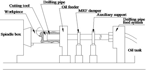
Fig. 1The deep hole drilling machine
2. The research foundation of vibration suppression damper
2.1. Analysis of drilling shaft system model
The BTA drilling machine is shown in Fig. 1. The cutting mechanism of deep hole drilling is to install the specially configured so called oil feeder. The cutting tool can be cooled or lubricated by the high-pressure cutting fluid injecting into the cutting region, and simultaneously, the cutting fluid with the chip is ejected from the tool shaft inner hole. Good sealing function is achieved due to axial clamping strictly between the oil feeder and the workpiece.
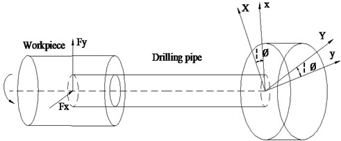
According to the actual characteristics of the deep hole drilling, the deep hole drilling shaft system can be simplified, as in the model shown in Fig. 2. Deng and Chin have established an equation system to describe the drilling system with pronounced shaft length, carried out simulation on the formation mechanism of the corrugated deep hole, and predicted the hole roundness by use of the Euler-Bernoulli beam equation. In their formulation, they ignored the influence of the shear deformation and torsion effect on the drilling shaft, the boundary condition of drilling shaft system is considered as a fixed, simply supported beam, and thus the governing equation of the drilling shaft system can be written as follows:
where is the density of the drilling shaft; is the cross-sectional area of the drilling shaft; and are the Young’s modulus and the moments of inertia respectively; is the rotating speed of drilling shaft; is the Dirac-delta function, and ; is the length of drilling shaft.
Fig. 2The deep hole drilling model
The dynamic morphology trajectory of the machined hole surface can be expressed as Eq. (2); at the same time, Equation (1) can transform into Eq. (3):
The deep hole drilling force is described as a Fourier series by Matin [12] as shown in Eq. (4), where , and is constant values, and is the workpiece surface non-uniform cutting coefficient [13]:
After solving the Eq. (3) and Eq. (4) by using eigenfunction expansion, the can be expressed as , where and are the mode and modal coordinates of the system, respectively. can be expressed by:
In the Eq. (5), , , and are constants; is an undetermined constant of the th mode [14], which can be determined by vibration mode function expression of the beam as Eq. (6):
Substituting Eq. (6) into Eq. (3), the dynamic morphology trajectory of the machined surface in deep hole drilling can be obtained as follows:
In Eq. (7), it can be seen that the dynamic morphology trajectory of the hole surface is the summation of many modal effects. In other words, the surface quality of the hole in deep hole drilling is directly related to the vibration modes of the drill tool that come into existence. This inspires the idea of targeted suppressing, which is simply to knock out the existence of certain harmful vibration modes to neutralize its damage or to force the vibration morph into less harmful modes to curb its damage.
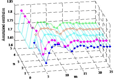
At the same time, Deng and Chin think that the major dynamic morphology trajectory is contributed by the first mode (1) and the first harmonic (1) as shown in Fig. 3. This provides the convenience for the theoretical calculation of roughness.
Fig. 3Accumulated contribution of number of modes (n) and number of harmonics (m) to the dynamic morphology trajectory (um)
2.2. The working principle of the squeezing mode MRF damper
According to the material performance and magnetorheological effect of MRF, there are three working modes of the MRF damper: flow mode of fixed electrode plates, shear mode of slide electrode plates, and squeeze damper, which usually works in the engineering application.
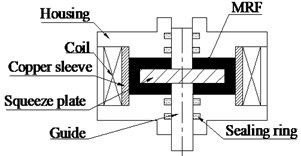
The squeezing mode MRF damper is shown in Fig. 4. The MRF is in the closed cavity formed by two flat plates. When the guide rod drives the pressing plate moves up and down, the plate spacing between the piston and the housing will be smaller. The MRF squeezed by the squeeze plate is forced to flow on all sides, where its direction perpendicular to the direction of the electromagnetic coil generates a magnetic field. Applying a magnetic field, the rheological properties of MRF are rapidly and reversibly altered, and produced yield stress to resist the movement. By changing the current strength of the excitation coils, the damping force that the damper output is controlled.
The damp power outputs from the squeezing mode MRF damper consists of two parts, squash and stretch, respectively. Magnetorheological fluid is suffered squeeze by the extrusion of equal area, and with the sealing effect and squeezing enhancing effects in the extrusion process, higher damping forces are made.
Fig. 4The squeezing mode MRF damper working principle diagram
3. Analysis and design of squeeze mode MRF damper
3.1. The MRF damper design and structure principle
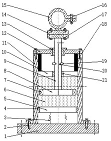
On the basis of the actual process condition and working principle of MRF, a squeeze mode MRF damper is designed and applied in deep hole processing as shown in Fig. 5.
The pedestal is fixed on the machine and the piston rod is connected with the drill pipe. The drill pipe moves up and down and the induction coil generates electricity, which spreads to the bottom of the piston rod and forms an electric field by cutting the magnetic induction line under the situation of vibration. The excitation coil generates a magnetic field; by cutting the electric field; the MRF produces a magnetorheological effect and consumes the vibration energy, so as to achieve the aim of damping. The spring is located below to compensate for variations in MR fluid volume due to the moving piston. Different levels of vibration can make the damper generate a different magnetic field strength, resulting in a different value of damping force. Under the smaller distance moving the damper can produce larger yield stress of MRF. In addition to the external current, the vibration damper can also use the permanent magnet system it comes with, to generate an electric current, and may at any time control the current intensity according to different vibration strength, at the same time, it avoids vibration suppression effect is not an ideal phenomenon, due to the fact that the current strength isn’t changed in time. As shown in Fig. 1, for an MRF damper it is installed in the position of the deep hole machine.
The squeeze mode Magnetorheological fluid damper with a smaller displacement distance, can have a greater Magnetorheological fluid yield stress, and avoid the phenomenon that the damping force generated can’t fully suppress the generation of chatter. Another important advantage is that it can also be used within the system and comes with a permanent magnet to generate a current in addition to the external current; it keeps control of the current intensity depending on the intensity of vibration, and thus the magnetic field strength is also subject to change; In the meantime, to avoid the phenomenon of vibration suppression effect is not unsatisfactory, and avoids the uncontrollable flutter phenomenon when there is input current failure.
Fig. 5The MRF damper structure principle diagram: 1 – pedestal; 2 – screw; 3 – spring; 4 – seal gland A; 5 – storage separator; 6 – MRF; 7 – excitation coil; 8 – piston; 9 – piston rod; 10 – magnetism isolating dead plate; 11 – housing; 12 – end cover; 13 – guid; 14 – connecting plate; 15 – fixed collar; 16 – drawblot I; 17 – drawblot II; 18 – permanent magnet; 19 – induction coil; 20 – conductor; 21 – seal gland B
3.2. Analysis of MRF damper damping force
As shown in Fig. 6, according to the structure design of the MRF damper, damping clearance between the piston and housing is very small compared with the piston diameter, the flow of the MRF in the damping channel can be approximate to the flow of fluid between the parallel plate. Therefore, the damping force of the damper is calculated by Bingham model [15].
Studying in hydrodynamics, can get the speed of the MRF within the whole damping gap:
In the Eq. (8): shows the MRF in yield flow state, shows the MRF in rigid flow state, shows the MRF in yield state, is the pressure difference of the damping channel at both ends, is the viscosity coefficient of magneto rheological fluid under zero magnetic field.
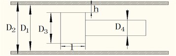
The structure of the MRF damper is schematically shown in Fig. 6. In the diagram, is the inner diameter of crock canister, is the outer diameter of crock canister, is the piston diameter, is the piston mast diameter; is the damping gap size; is the active length.
Fig. 6MRF flow diagram of a Bingham plastic model of parallel plate
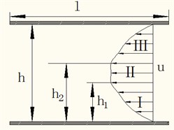
Fig. 7The structure and size diagram of the MRF damper
According to the conservation of mass, velocity formula is of the form Eq. (9):
In the Eg. (9): is the working area of piston, is the equivalent width of the damping channel and is piston speed.
When , the Eq. (9) can be simplified as:
where the dimensionless velocity of the piston is , and and are the dimensionless pressure gradient and yield stress, defined by:
If the piston head velocity , then, 0, and Eq. (10) becomes a cubic Equation for . This cubic Equation has the realizable root at [16]:
In general, Eq. (10) cannot be solved analytically, but a solution may be easily obtained numerically. An approximate solution can be used to estimate the desired root for 01000 and –0.50, encompassing most practical designs in which the flow is in the opposite direction of the piston velocity [17]:
As illustration of force decomposition for MR dampers by G. Yang [18], the damper resisting force can be decomposed into a controllable force due to controllable yield stress and an uncontrollable force . The uncontrollable force includes a viscous force and a friction force . Based on the parallel-plate model, and are defined as:
And , bounded to the interval [2.07, 3.07], which Spencer Jr. has been studied [17].
The controllable force in Eq. (14) can also be rewritten using Eq. (11) as:
Therefore, the friction force is a constant, then, the dynamic range tends to zero. The total damping force provided by the MFR damper can be expressed as:
where is the compensation coefficient, is the shear stress of the MRF in yield state. With the real-time changes of the piston velocity , the MRF damper can make corresponding changes promptly to provide damping force. On the other hand, the controllable force range is inversely related to the gap size . To maximize the effectiveness of the MR damper, the controllable force should be as large as possible, so a small gap size is required. Ultimately to achieve active regulation and control of drill shaft system damping and stiffness.
4. The experimental confirmation
4.1. Experimental arrangement and conditions
In order to evaluate the effectiveness of the design, the lateral vibration signals of drilling shaft, the machined hole surfaces, the drilling tool and the guide pad surface wear patterns are analyzed through contrast drilling tests on applying damper and having no damper. According to the Eq. (7), the surface roughness of the workpiece without the damper vibration suppression is studied. The experimental equipment is set up on a deep hole drilling with rotary workpiece, the others experimental arrangements are shown in Table 1. Due to the deep hole drilling equipment for a multi-span support system, the installation position of a damper is another important factor to affect the drilling tool vibration. Three contrast experiments are carried out under the conditions with different installation position and the vibration suppression damper is energized with different coil currents of 0 A and 1.5 A. The vibration signals of the drilling shaft are collected through the acceleration transducer.
Table 1Details of the experimental arrangements
Cutting tool | BOTEK |
Spindle speed (r/min) | 360 |
Workpiece material | EA4T |
Feed rate(mm/min) | 16 |
Cutting fluid pressure (MPa) | 5 |
Drilling depth (mm) | 2440 |
Bore hole diameter (mm) | 30 |
4.2. Vibration experiment results and discussion
After the completion of drillings with and without installing the damper, a comparative analysis of the drilling tool wear patterns and the machined hole quality by high depth of field microscope, are shown respectively in Figs. 8-10. The theoretical value of the machined surface is shown in Fig. 10.
Fig. 8The vibration responses of drilling shaft with the installed position of the vibration suppression damper is 650 mm away from the tool head, and the coil currents of 0 A and 1.5 A, with the frequency response curves
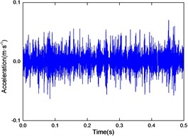
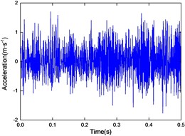
a) 0 A
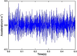
b) 1.5 A
c) Frequency response curves
Fig. 9The vibration responses of drilling shaft with the installed position of the vibration suppression damper is 650 mm away from the tool head, and the coil currents of 0 A and 1.5 A, with the frequency response curves
a) 0 A
b) 1.5 A
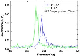
c) Frequency response curves
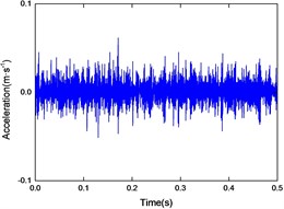
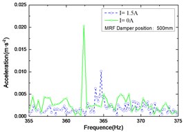
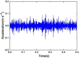
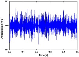
Fig. 10The vibration responses of drilling shaft with the installed position of the vibration suppression damper is 650 mm away from the tool head, and the coil currents of 0 A and 1.5 A, with the frequency response curves
a) 0 A
b) 1.5 A
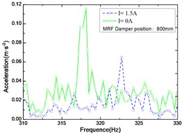
c) Frequency response curves
Fig. 8-10 shows the responses of coil currents of 0 A and 1.5 A, suppressed by the MRF damper mounted at a distance of 500 mm, 650 mm and 800 mm from the tool head respectively. From Figs. 8-10 it can be seen that the suppression effects with coil currents are much better than without coil currents. Although far from the cutting tool, the same conclusion can be made from Fig. 10, that persuasively verifies the effectiveness of the damper vibration suppression. Comparing Fig. 8, Fig. 9 and Fig. 10 respectively, the position of the damper has an obvious effect on the lateral vibration of the shaft system. With the change of the damper installation position, the vibration suppression effect also changes accordingly, and the closer distance from the cutting tool that the damper installed, the better effectiveness of vibration suppression when the drilling shaft isn’t long enough. While the vibrational frequency is manifesting strong nonlinearity, on the other hand, the frequency shifts effect and amplitude reducing efficiency of vibration suppression can effectively improve the stability of deep hole drilling.
4.3. Experimental and theoretical values of the machined surfaces
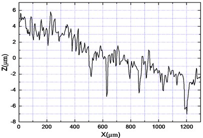
Additionally, Figs. 11-13 show that the experimental and theoretical values of the machined surfaces are in agreement in trend. It also can be seen that the picture of the machined hole surface, before and after vibration suppression in Fig. 11, and the theoretical research results, are smaller as a result of the actual processing being more complex. When the damper installation position distance of the tool is 500 mm, the roughness value decreases to 1.69 from 3.53, and along with the damper installation position being different, the roughness is different. After synthetically analyzing Figs. 11-13, it can be seen that the machined hole surface quality is better when the damper is installed on a distance of 650 mm, rather than when the distance is 800 mm under the same condition of 1.5 A, and the smallest roughness with 1.69 is obtained when the damper is installed on a distance of 500 mm.
Fig. 11The theoretical values without a damper and the curve of surface roughness (Ra= 1.69 um, the electric current I= 1.5 A, the installed position of the vibration suppression damper is 500 mm away from the tool head)
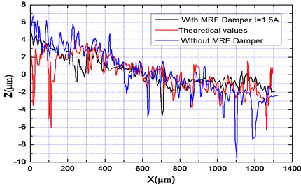
Fig. 12The curve of surface roughness (Ra= 2.16 um, the electric current I= 1.5 A, the installed position of the vibration suppression damper is 650 mm away from the tool head)
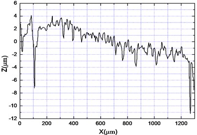
Fig. 13The curve of surface roughness (Ra= 3.53 um, the electric current I= 1.5 A, the installed position of the vibration suppression damper is 800 mm away from the tool head)
Not only did the chatter marks decrease clearly, but the surface roughness improvement degree was different, also present some non-linear features. This typical phenomenon is mainly due to the MFR damper acting locally on the drilling shaft, and the effects are global and coupled with each other from the drilling tool geometric parameters, cutting parameter, the cutting fluid whirling motion and nonlinear MRF damping force. The coupled effect results in irregular changes of the drilling tool vibration behavior, which cause the cutting trajectory and thickness of the drilling tool acting on the workpiece surface to be non-uniform. However, the vibration suppression principle suggested and implemented in this paper has been proven effective in improving the hole machining qualities.
4.4. The influence of vibration
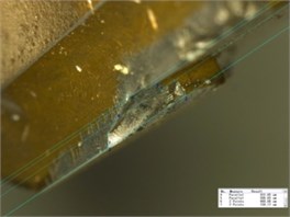
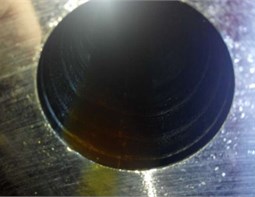
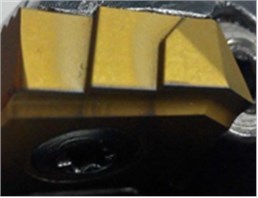
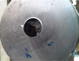
It is clearly observed from Fig. 14(a) that there were a series of severe oxidation wear and adhesion wear phenomena on the oriented surface of the guide pad, and obvious damage on the edge of the guide pad. The unsatisfactory situation occurred is due to the bending and twist distortion of the drilling shaft, which leads the drilling tool axis to deviate from the central line of the machined hole, at the same time, along with the guide bar installed on the drilling tool was also tilted, and the force applied on the vulnerable area for the guide bar edge is too excessive and causes breakage. A strange phenomenon emerged, in that the cutting edge was damaged, but the wear phenomenon was a rare occurrence. That lead to speculation that the particular results were mainly caused by strong vibration, and the presence of the rifling mark caused by vibrations, which exacerbated the wear of the guide pad surface. In Fig. 14(b), the phenomenon of the index-able insert rack tipping was obvious; the chip separation step breakage and the cracking-off problem of flank face were serious, which also led to the large-scale increase of the long curly chips and irregular chips or even caused chip congestion, and could not been removed from the drilling shaft. In Fig. 14(c), the spiral pattern called a “rifling mark” is formed on the machined hole surface, and the “rifling mark” made the wear of the guide pad worse. Fig. 15 revealed the tool condition after installing the damper. The desquamation of the coating from the index-able insert rack face is receded, and the breakage of the cutting edge is weakened. In addition, the wear pattern of the guide pad face becomes a narrow sheet distribution. The rifling mark formed on the surface of the bore is decreased distinctly, and consequently, the quality of deep holes is better than has none of damper, this means that the system stability has been improved observably. In Fig. 15(a), there is a slight wear phenomenon caused by intense dynamic friction. It was the essential attribute of the guide pad, which was stringent in contact with the machined hole surface.
Fig. 14The cutting tool shape obtained from the experiment has none of a damper
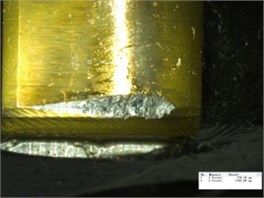
a) The damaged guide pad edge
b) The breakage of cutting edge
c) Rifling mark
Fig. 15The cutting tool shape obtained from experiment, having installing a damper
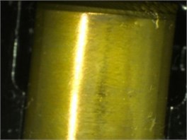
a) The guide pad surface
b) The indexable insert
c) High quality hole
5. Conclusions
According to the working principle of squeezing mode MRF, if the MRF damper used for the suppression of drilling shaft-tool vibration in deep hole drilling, it can provide real-time response instantaneously to suppress the vibration. Considerable gains can be made by using the MRF in deep hole machine.
Both the contrast drilling experiments before and after applying damper and theory research obviously verified that it has a better performance of active control to suppress the shaft-tool system vibration significantly under the action of the vibration suppression damper, and accompanied by frequency shift, it effectively improves the surface quality of machined holes. The experimental and theoretical values of the machined surfaces are in agreement in trend, and the closer distance from the cutting tool that the damper installed, the better effectiveness of vibration suppression.
It’s also possible to provide practical experience and with this, the vibration characteristic can be analyzed by observing the drilling tool and the guide surface wear patterns. When the worse wear patterns appear, the magnetic field strength of the magneto-rheological fluid can be enhanced suppress the drill vibration, or even tools should be changed to guarantee the quality of the drilling hole.
The damper isn’t fully suppressing the vibration, but shows nonlinear characteristics, mainly due to the result of multi-factors coupling in deep hole drilling. The vibration suppression effect is different from the installation position of the damper; the closer distance from the cutting tool that the damper has installed, the better effectiveness of vibration suppression, to the extent that the machined hole surface is also different, and the best suppression of the damper is also related to the installation position of damper and the drilling depth. Further study will be carried out to work towards producing the least amount of roughness in the future.
References
-
Mehrabadi I. M., Nouri M., Madoliat R. Investigating chatter vibration in deep drilling, including process damping and the gyroscopic effect. International Journal of Machine Tools and Manufacture, Vol. 49, 2009, p. 939-946.
-
Matsuzaki Kenichiro, Ryu Takahiro, Sueoka Atsuo, Tsukamoto Keizo Theoretical and experimental study on rifling mark generating phenomena in BTA deep hole drilling process (generating mechanism and counter measure). International Journal of Machine Tools and Manufacture, Vol. 88, 2015, p. 194-205.
-
Ema S., Marui E. Theoretical analysis on chatter vibration in drilling and its suppression. Journal of Materials Processing Technology, Vol. 138, 2003, p. 572-578.
-
Sakuma K., Taguchi K., Katsuki A. Study on deep-hole boring by BTA system solid boring tool-behavior of tool and its effect on profile of machined hole. Journal of the Japan Society for Precision Engineering, Vol. 14, 1980, p. 143-148.
-
Marui E., Kato S., Hashimoto M., Yamado T. The mechanism of chatter vibration in a spindle-workpiece system. Part 1: properties of self-exited vibration in spindle-workpiece system. Journal of Engineering for Industry, Vol. 110, 1988, p. 236-241.
-
Kong L. F., Li Y., Lu Y. J., Zhao Z. Y., Hou X. L. A nonlinear dynamic finite element analysis of drilling shaft including multispan auxiliary supports in deep-hole machining. Advances in Mechanical Engineering, Vol. 5, 2013, p. 735081.
-
Al-Wedyan Hussien M., Bhat Rama B. Whirling vibrations in boring trepanning association deep hole boring process: analytical and experimental investigations. Manufacturing Engineering Division, Vol. 129, Issue 1, 2007, p. 48-62.
-
Ashour O., Rogers C. A., Kordonsky W. Magnetorheological fluids: materials, characterization, and devices. Journal of Intelligent Material Systems and Structures, Vol. 7, 1996, p. 123-130.
-
Ioan B., Liu Y. D., Choi H. J. Physical characteristics of magnetorheological suspensions and their applications. Journal of Industrial and Engineering Chemistry, Vol. 19, 2013, p. 394-406.
-
Farjoud A., Craft M., Burke W., Ahmadian M. Experimental investigation of MR squeeze mounts. Journal of Intelligent Material Systems and Structures, Vol. 22, 2011, p. 1645-1652.
-
Hemmatian M., Ohadi A. Sliding mode control of flexible rotor based on estimated model of magnetorheological squeeze film damper. Journal of Vibration and Acoustics, Vol. 135, Issue 5, 2013, p. 051023.
-
Rahman M., Matin M. A., Seah K. H. W. A study of the vibrational dynamics of an endrill clamped by side-locking. Journal of Engineering for Industry, Vol. 115, 1993, p. 438-443.
-
Deng C. S., Chin J. H. Roundness errors in BTA drilling and a model of waviness and lobing caused by resonant forced vibrations of its long drill shaft. ASME, Journal of Manufacturing Science and Engineering, Vol. 126, 2004, p. 524-534.
-
Dimarogonas A. Vibration for Engineering, 2nd Ed. Prentice Hall International Editions, New Jersey, 1996.
-
Carlson J. D., Jolly M. R. MR fluid, foam and elastomer devices. Mechatronics, Vol. 10, 2000, p. 555-569.
-
Gavin H. P., Hanson R. D., Filisko F. E. Electrorheological dampers. Part 1: analysis and design. ASME Journal of Applied Mechanics, Vol. 63, Issue 9, 1996, p. 669-675.
-
Spencer Jr. B. F., Yang G., Carlson J. D., Sain M. K. Smart dampers for seismic protection of structures: a full-scale study. Proceedings of 2nd World Conference on Structural Control, Vol. 1, 1998, p. 417-26.
-
Yang G., Spencer B. F., Carlson J. D., et al. Large-scale MR fluid dampers: modeling and dynamic performance considerations. Engineering Structures, Vol. 24, Issue 3, 2002, p. 309-323.
About this article

This work was financially supported by the National Natural Science Foundation of China (51175482) and International S&T Cooperation Program of China (2013DFA70770).
