Abstract
In order to get the more accurate damping capacity and durability of MR damper in the real vehicle conditions. On the basis of fully understanding the working state and damping regulation principle of the MR damper, taking the control current of the MR damper as the variable, the damping characteristic curves under different control currents are obtained. Based on Miner's law and the theoretical support of pseudo damage, through the durability comparison test under three different current control logic combination conditions, a more suitable reliability durability test method for the MR damper is obtained. The results show that under the condition of specific current, the damping value of MR damper will increase with the increase of speed; Under the condition of specific speed, the damping value of MR damper will decrease with the increase of current, and the damping value of MR damper is maximum when there is no current through; The results show that the verification methods that check the damping force and oil leakage of the shock absorber under three different conditions are effective. The second dual frequency durability test method under the condition of current control logic combination can not only shorten the duration of the whole durability test, but also take into account the impact of current change on the durability of the shock absorber, and has more popularization and application value.
1. Introduction
With the rapid development of China’s automobile industry and the gradual increase of people's demand for cars, China's automobile manufacturing level has also been greatly improved. In particular, the development of automobile suspension system has also experienced many rounds of updating iteration. From the general passive suspension to the active suspension which can be adjusted adaptively according to different road conditions. In the automotive active suspension system, the damper with continuously adjustable damping plays an important role. On the one hand, it can provide a reliable guarantee for the safe driving of the car. On the other hand, it can adjust the damping coefficient according to the road impact and vibration feedback to improve the riding comfort and driving stability.
With the continuous development of electronic control damping technology, as an important actuator of active suspension, MR damper has become the main research direction of active suspension because of its relatively simple structure, controllable damping, fast response rate, large adjustable coefficient, relatively simple control logic and low energy consumption. Guo et al. [1] explored the application of electronic control vibration reduction technology in automotive suspension system. Lei et al. [2] described the research status and development trend of new shock absorbers. Peng et al. [3] of the Army Armored Forces Academy conducted in-depth research and real vehicle road test analysis based on the self-developed parallel constant through-hole magnetorheological damper and control system. The developed magnetorheological suspension system significantly improves the ride comfort, handling stability and driving safety of the vehicle. The University of Maryland [4] deeply analyzed the design parameters and control theory of MR damper, and developed a single cylinder pneumatic compensation MR damper. The University of Notre Dame [5] developed a similar Magnetorheological Shock Absorber and conducted experimental research. It changed the material of the working cylinder to electromagnetic pure iron, which improved the magnetic conductivity of the whole magnetic circuit. Zhang et al. [6] deeply studied the influence of structural parameters on the performance of single barrel Magnetorheological Shock absorber, built a multi-objective optimization model of Magnetorheological Shock Absorber for structural optimization design, and verified the reliability of the optimization solution in the form of experimental verification. Xu [7] studied the predictive control strategy for the road preview model of magnetorheological semi-active suspension. Seong et al. [8] studied the control model of MR damper considering the hysteresis characteristics of magnetic field damping. Arsava et al. [9] studied the fuzzy controller of magnetorheological damper based on acceleration feedback. Li [10] studied the friction characteristics of Magnetorheological Shock Absorber with unmagnetized channel through experiments. Goldasz and Sapinski and Sohn et al. [11-13] established the mathematical model of non magnetized channel magnetorheological damper, Warczek et al. [14] studied the shock absorber parameters of vehicle suspension through simulation, tested the damping characteristics of the shock absorber under different frequencies and different working strokes, and obtained that the motion frequency of the shock absorber has a great influence on its damping force.
In this paper, three MR dampers of the same specification (working stroke 120 mm, working current 0-3 A) are selected for testing. Taking the control current of MR damper as variable, the damping characteristics of MR damper were tested under different control current conditions. Through the test results, the relationship between current variable and damping characteristics of MR damper is analyzed. Based on Miner's rule and the theory of pseudo damage, three conditional durability tests of different current control logic combinations are carried out for MR damper, and a reliability durability test method for MR damper is obtained.
2. Test method of MR damper damping characteristics
According to the national automotive industry standard QC/T 491-2018 “Automobile shock absorber technique requirements and test methods” and the performance test specifications for electric shock absorbers of some enterprises, this test adopts the German its shock absorber comprehensive performance test bench to carry out relevant tests on Magnetorheological Shock absorbers. The specific conditions for the resistance characteristic test are as follows:
1) Preparation before test: First, place the shock absorber sample in a vertical free state at room temperature (23 ± 3 ℃) for more than 2 h, then install it vertically on the shock absorber test bench, and adjust the shock absorber piston rod to the middle of its working stroke;
2) Damper exhaust: After the shock absorber is installed, conduct 3 cycles of exhaust process before the formal test. The exhaust process is conducted at the maximum speed of 0.52 m/s (stroke S=100mm, frequency 1.67 hz);
3) Damping force test: After the exhaust process is completed, the test shall be carried out in sine wave mode with an amplitude of ±50 mm, and the working current 0 A, 0.5 A, 1.0 A, 1.5 A, 2.0 A, 2.5 A and 3.0 A shall be adjusted respectively. The displacement and load data of the shock absorber at the speed of 0.13 m/s, 0.26 m/s, 0.52 m/s, 0.78 m/s and 1.04 m/s shall be tested under the condition of each working current.
3. Test results of MR damper damping characteristics
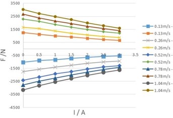
According to the test method of MR damper damping characteristics, the compression resistance and recovery resistance under each working current and speed are obtained. Due to space reasons, only the velocity characteristic data of one MR damper is listed in Table 1, and the damping characteristic curve of MR damper is drawn, that is, the damping force velocity (F-V) curve is shown in Fig. 1 and the damping force current (F-I) curve is shown in Fig. 2.
Table 1Test results of MR damper damping characteristics
Speed (m/s) | Compression resistance (N) | Recovery resistance (N) | ||||||||||||
0 A | 0.5 A | 1.0 A | 1.5 A | 2.0 A | 2.5 A | 3.0 A | 0 A | 0.5 A | 1.0 A | 1.5 A | 2.0 A | 2.5 A | 3.0 A | |
0.13 | –1047 | –912 | –852 | –751 | –670 | –595 | –555 | 1237 | 1101 | 980 | 899 | 795 | 702 | 635 |
0.26 | –1765 | –1588 | –1421 | –1278 | –1128 | –1023 | –955 | 1639 | 1543 | 1354 | 1182 | 1051 | 935 | 849 |
0.52 | –2433 | –2185 | –1936 | –1766 | –1571 | –1407 | –1310 | 2274 | 2098 | 1855 | 1650 | 1468 | 1303 | 1186 |
0.78 | –2792 | –2502 | –2263 | –2026 | –1805 | –1609 | –1435 | 2654 | 2359 | 2122 | 1927 | 1713 | 1546 | 1376 |
1.04 | –3177 | –2843 | –2557 | –2301 | –2056 | –1833 | –1644 | 3012 | 2697 | 2463 | 2236 | 1977 | 1765 | 1573 |
According to the test results of the damping characteristic test of MR damper, it is analyzed that under the condition of specific current, the damping value of MR damper will increase with the increase of speed as shown in Fig. 1; Under the condition of specific speed, as shown in Fig. 2, the damping value of MR damper will decrease with the increase of current, and the damping value of MR damper is the largest when it is not powered on.
Fig. 1F-V curve of 01 MR damper under different currents
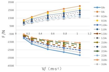
Fig. 2F-I curve of 01 MR damper at different speed
4. Three durability test methods
4.1. Method 1: Dual frequency endurance test without power on
Through the analysis of the test results of the damping characteristics of MR damper, it is pointed out that the damping value of MR damper is the largest when it is not powered on, so the current value of this method is 0 A. In combination with the durability test method in QC/T 491-2018 “Automobile shock absorber technique requirements and test methods”, the current mainstream shock absorber test bench is used to conduct the dual frequency durability test in the way of single action simulating double action, that is, the upper end of the shock absorber is fixed, and the lower end of the shock absorber is connected with the actuator to apply the superimposed wave formed by the superposition of high-frequency signal and low-frequency signal. The superimposed waveform is shown in Fig. 3.
Superimposed wave signal: Low frequency (upper end) test condition: 1 Hz, test stroke 80 mm; High frequency (lower end) test conditions are 12 Hz, test stroke 20 mm.
4.2. Method 2: Dual frequency endurance test under current control logic
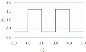
Under the condition of current control logic, the dual frequency durability test method is to introduce current as the control variable on the basis of method 1. During operation, the high and low current (comfort mode 0.32 A, motion mode 1.6 A) of the shock absorber each accounts for 50 % of the life cycle. The current signal waveform is shown in Fig. 4. The double frequency durability test is also carried out in the way of single action simulating double action, and the loaded waveform is the same as the superimposed wave in method 1.
Fig. 3The superimposed wave signal of dual frequency durability test
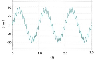
Fig. 4The current signal waveform
4.3. Method 3: Road spectrum reliability test under current control logic
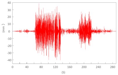
The road spectrum reliability test can more truly restore the stress state of the shock absorber on the real vehicle and is closer to the actual service condition of the shock absorber. This durability test method is also added to QC/T 491-2018 “Automobile shock absorber technique requirements and test methods”, which is the development trend of durability test in the future. Under the condition of current control logic, the road spectrum reliability test method adds the current control signal of the electric shock absorber (the current control signal used this time is the same as that described in method 2, as shown in Fig. 4) on the basis of the road spectrum reliability test specified in the standard, and then combines the displacement signal of the relative movement of the piston rod at the upper end of the shock absorber and the shock absorber cylinder as the target signal to conduct the road spectrum reliability bench test. The selected shock absorber displacement road spectrum signal (as shown in Fig. 5) is the road spectrum signal collected by a vehicle type on a test site for subsequent calculation and verification.
Among the three test methods, the test scheme of method 1 is simple and the operation is the most convenient, but the influence of current on the performance of the shock absorber is not considered in the test process, and the evaluation is directly carried out when the damping force of the shock absorber is at the maximum value; Method 2 considers the influence of current on the performance of shock absorber; Method 3 not only considers the influence of current on the performance of shock absorber, but also considers the influence of road vibration on the durability of shock absorber, which is closer to the working condition of shock absorber in the process of vehicle driving.
Fig. 5The displacement road spectrum signal
5. Miner’s rule and pseudo damage equivalent theory calculation
In general, when calculating the fatigue damage of parts, we will first obtain the stress load of parts by means of CAE simulation or verification test, then draw its S-N curve, and then calculate the damage value by using the fatigue damage accumulation method. However, according to QC/T 491-2018 “Automobile shock absorber technique requirements and test methods”, the shock absorber durability test focuses on the attenuation of the shock absorber damping force under different working conditions, not the fatigue of metal structures. However, the control signal applied by the shock absorber is a displacement signal, and the relationship between the displacement and stress-strain of the shock absorber is nonlinear. As an electronically controlled damping element, it is greatly affected by the change of current. Therefore, it is difficult to obtain the relatively real damage value of the shock absorber if the displacement is assumed as the stress input without considering the specific form of the load.
In view of the above problems, we try to use the verification test method to take a section of shock absorber load data by using the data acquisition device under three durability methods (data duration: 10 s for method 1 and method 2 respectively, 280 s for method 3). The purpose of this damage equivalent calculation is to find the correlation between the three different methods. Therefore, the specified S-N curve is used to count the cycle and calculate the damage of the load spectrum data based on Miner’s law, and the relative damage value is used to establish the equivalent relationship under the three test methods.
The simplest S-N curve can be expressed by Basquin equation:
where is material parameters, is stress amplitude, is damage index, is fatigue life under amplitude load.
Then, Miner’s rule is used to sum the damage of each amplitude:
where is cumulative damage.
The specific numerical calculation is completed by ncode software, and the calculation results are shown in Table 2. QC/T 491-2018 requires that the number of dual frequency durability tests is 3 million cycles (high frequency counting). Assuming that method 1 needs 3million cycles, it can be concluded that method 2 needs to run 3832832 cycles and method 3 needs to run 34357 spectrum cycles according to the pseudo damage calculation results.
Table 2Pseudo damage calculation results
Signal type | Length of time (s) | Pseudo damage value |
Load signal acquisition in method 1 | 10 | 2.973E-05 |
Load signal acquisition in method 2 | 10 | 2.327E-05 |
Load signal acquisition in method 3 | 280 | 2.596E-04 |
6. Bench verification test and test results
In this paper, three identical shock absorbers are selected, and one of them is selected to carry out the durability test according to the standard requirements of methods 1, 2 and 3 according to the times calculated according to the pseudo damage. In order to eliminate the influence of temperature on the test results, forced cooling measures are adopted during the durability test to keep the temperature of shock absorber at 70±10 ℃. In order to eliminate the influence of personnel and equipment on the test results, this test is conducted by the same personnel on the same equipment.
The test results only need to assess the damping force attenuation and oil leakage. Before and after the durability test, measure the damping force value of the shock absorber at the speed of 0.52 m/s (for method 1, the measured current is 0 A, for method 2 and method 3, the measured current is 0.32 A and 1.6 A respectively). See Table 3 for the test results.
Table 3Durability test results of three methods
Sample No. | Test method | Current conditions | Test items | Before test (N) | After test (N) | Attenuation rate | Whether there is oil leakage |
1# | Method 1 | 0 A | Recovery resistance | 2271 | 2065 | 9.1 % | No |
Compression resistance | 2442 | 2186 | 10.5 % | No | |||
2# | Method 2 | 0.32 A | Recovery resistance | 2156 | 1969 | 8.7 % | No |
Compression resistance | 2299 | 2088 | 9.2 % | No | |||
1.6 A | Recovery resistance | 1613 | 1466 | 9.1 % | No | ||
Compression resistance | 1725 | 1547 | 10.3 % | No | |||
3# | Method 3 | 0.32 A | Recovery resistance | 2148 | 1944 | 9.5 % | No |
Compression resistance | 2303 | 2050 | 11.0 % | No | |||
1.6 A | Recovery resistance | 1609 | 1458 | 9.4 % | No | ||
Compression resistance | 1722 | 1536 | 10.8 % | No |
From the test results shown in Table 3, it can be seen that among the test results of the three methods, except that the attenuation rate of the test results is slightly lower when 0.32A of method 2, the results of other test conditions have little difference, and the results are consistent. When the same damage occurs, method 3 takes a long time, and the results of method 2 are relatively close to the results of method 3, and are relatively close to the real vehicle test.
7. Conclusions
1) Through the analysis of the test results of MR damper damping characteristics, the damping characteristics of MR damper, under the condition of specific current, the damping value of MR damper will increase with the increase of speed; Under the condition of specific speed, the damping value of MR damper will decrease with the increase of current, and the damping value of MR damper is the largest when it is not powered on.
2) Based on the theory of damage equivalence, the equivalent relationship among the three is established by using miner’s rule and pseudo damage calculation. Through the verification of three different test methods, the durability test methods under three different current control logic conditions are effective.
3) Method 2: the dual frequency durability test method under the condition of current control logic can not only shorten the duration of the whole durability test, but also take into account the impact of current changes on the durability of shock absorbers, which is more worthy of popularization and application.
References
-
C. J. Guo, H. B. Zhong, Q. Yin, and Y. Z. Lu, “An analysis of the application of electronically controlled vibration reduction technology in automobile suspension system,” Auto Time, No. 16, pp. 155–156, 2020.
-
X. H. Lei, X. Liu, and X. T. Liu, “Research status and development trend of new type shock absorber,” Automobile Applied Technology, Vol. 45, No. 24, pp. 236–239, 2020, https://doi.org/10.16638/j.cnki.1671-7988.2020.24.078
-
Z. Z. Peng, Y. T. Wei, X. W. Fu, and X. J. Yao, “Research and performance test of magnetorheological semi-active suspension system based on a real vehicle,” Automotive Engineering, Vol. 43, No. 2, pp. 269–277, 2021, https://doi.org/10.19562/j.chinasae.qcgc.2021.02.016
-
J. E. Lindler, G. A. Dimock, and N. M. Wereley, “Design of a magnetorheological automotive shock absorber,” in SPIE’s 7th Annual International Symposium on Smart Structures and Materials, Vol. 3985, pp. 426–437, Jun. 2000, https://doi.org/10.1117/12.388845
-
S. P. Kelso and F. Gordaninejad, “Magnetorheological fluid shock absorbers for off-highway high-payload vehicles,” in 1999 Symposium on Smart Structures and Materials, Vol. 3672, pp. 44–54, Jun. 1999, https://doi.org/10.1117/12.349803
-
L. X. Zhang, C. Y. Zheng, F. Q. Pan, and B. Q. Lin, “Multi-objective optimization and experimental study on the single-cylinder magnetorheological damper,” Science Technology and Engineering, Vol. 20, No. 36, p. 14914, 2020.
-
M. S. Xu, “Research on road preview model predictive control strategy for magneto-rheological semi-active suspension,” Jilin University, 2021.
-
M. S. Seong, S. B. Choi, and Y. M. Han, “Damping force control of a vehicle MR damper using a Preisach hysteretic compensator,” Smart Materials and Structures, Vol. 18, No. 7, p. 07400, 2009.
-
K. S. Arsava, Y. Kim, and K. H. Kim, “Fuzzy control for impact mitigation of coastal infrastructure equipped with magnetorheological dampers,” Journal of Coastal Research, Vol. 75, pp. 1037–1041, Mar. 2016, https://doi.org/10.2112/si75-208.1
-
G. J. Li, “A study on the dynamic characteristics of a magneto-rheological damper featuring piston non-magnetised paths,” South China University of Technology, 2020.
-
J. Goldasz and B. Sapinski, “Nondimensional characterization of flow-mode magnetorheological/electrorheological fluid dampers,” Journal of Intelligent Material Systems and Structures, Vol. 23, No. 14, pp. 1545–1562, Sep. 2012, https://doi.org/10.1177/1045389x12447293
-
J. W. Sohn, J. S. Oh, and S. B. Choi, “Design and novel type of a magnetorheological damper featuring piston bypass hole,” Smart Materials and Structures, Vol. 24, No. 3, p. 03501, 2015.
-
J. Goldasz and B. Sapinski, “Verification of magnetorheological shock absorber models with various piston configurations,” Journal of Intelligent Material Systems and Structures, Vol. 24, No. 15, pp. 1846–1864, Oct. 2013, https://doi.org/10.1177/1045389x13479684
-
J. Warczek et al., “Simulation of a visco-elastic damper based on the model of the vehicle shock absorber,” Journal of Vibroengineering, Vol. 17, No. 4, pp. 2040–2048, Jun. 2015.
Cited by
About this article

F. Pang would like to thank senior engineer Liu Wei and Dr. Niu Zhihui for their valuable discussions, which have improved the quality and presentation of the paper.
