Abstract
There are many conflicting viewpoints for friction force of MR damper. Readers may be lost in facing these conflicting viewpoints. In this study, a novel model of friction force of MR damper is proposed. This model tries to reveal the essence and help readers have a better understanding of friction force of MR damper. The model indicates that the friction force only relates to the current applied to the piston coil. The friction force will increase along with current applied to the piston coil. Friction force tests for a MR damper featuring bypass holes in piston were made on a MTS852 system. The model was improved to be correct by the experiment. Friction forces by calculation with the model and by experiment are in good agreement. It is believed that sliding friction and MR phenomenon contribute to the friction force.
Highlights
- A novel mathematical model for friction force was proposed.
- Friction force is nonlinear and enlarges along with the current applied to the piston coil.
- Calculated friction forces with this model matches well with experiment
1. Introduction
Magneto-rheological (MR) damper is a smart damper which has many excellent properties such as continuously variable damping, fast response in milliseconds, high authority at a low piston velocity, long term stability, simple electronics, straightforward controls, and so on. MR damper has been applied to automobile and construction industries, bridges, aerospace, etc. [1, 2].
Friction force of MR damper is significant and will generate the discontinuity of damping force, will degrade the performance, and will damage the stability, decreases the service life. Detailed study on friction force will be necessary and mechanism of friction force generation must be explored. However, there are many conflicting viewpoints for friction force of MR damper [3-7]. Hu W., Robinson R. and Norman W. [3] believe that the friction force is constant and generated from the contact of seal-rod. Andrzej M. et al. [4] and Fernando D. G. [5] indicate that the friction force is a function of shear rate. Hu Z. D. and Yan H., et al. [6] studied the wear of MR fluid using a modified four-ball tribological tester and found that the MR Fluid showed a controlled tribological property. Vardarajan R. I. et al. [7]. developed a unique seal wear test method to simulate the wear of sealing in MR damper. Readers may be lost in facing these conflicting viewpoints.
In this study, a novel model was proposed to describe the friction force of MR damper. No model for friction force of a MR damper has been found before. This model tries to reveal the essence of friction force of MR damper. Friction force tests of a MR damper under different excitation current were made on a MTS852 system. The MR damper is a commercial damper which is featuring an annular orifice and 3 bypass holes in piston. Results of tests indicate that the friction force increases along with current which is applied to piston coil. Friction forces by calculation and by experiment are in good agreement.
2. Friction model
When piston moves in cylinder of a MR damper, there is a sliding friction on the cylinder-piston surface and rod-seal surface. This sliding friction changes along with the roughness and pressure due to the side force acting on rod. We name this sliding friction force as the initial sliding friction force . After current is applied to the piston coil, the piston and cylinder will be magnetized. Cylinder and piston attract each other, and the pressure rises on cylinder-piston surface. Then the sliding friction force increases. We name the increment of sliding friction force as the current-related sliding friction force . Here is the current applied to the piston coil. The MR fluid around the piston will also be magnetized and turns into semi-solid one according to the MR phenomenon. As a result, the piston needs to overcome the yield stress of MR fluid first, and then moves. We name the force balancing the yield stress as the MR phenomenon-related friction force .
The total friction force of a MR damper can be given as:
As only relates with roughness and pressure due to the side force on the contact surface, it will remain constant during tests:
where equals to the friction force when no current is applied.
According to the Biot-Savart law and Lorentz force theory, the pressure on the cylinder-piston surface is approximately in direct proportion to . Hence:
where is a constant coefficient. The magnitude depends on the roughness of piston-cylinder surface and dimensions of piston.
According to the magnetization curve of MR fluid, and relation between the magnetization curve and yield force [8], the MR phenomenon-related friction force can be expressed as:
where and are constant coefficients. is a hyperbolic tangent function of . The magnitude of and depends on the magnetization curve of MR fluid and also the dimensions of piston.
3. Description of MR damper and test system
3.1. MR damper
The tested MR damper which is manufactured by BWI Corporation has 3 bypass holes in the piston. When the piston moves in the cylinder of MR damper under no current, the MR fluid goes through the annular orifice and bypass holes. When a large current is applied to the piston coil, a strong magnetic field only emerges in the annular orifice, and then MR fluid turns into semi-solid one and is hard to go through the annular orifice. As no magnetic field emerges in bypass holes, the MR fluid is always able to flow in bypass holes [1, 2].
3.2. Test system
The friction force of the MR damper was tested on the MTS852 system.
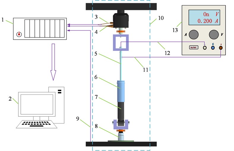
Fig. 1Experiment system for testing friction force of MR damper featuring three bypass holes: 1 – data-acquisition system, 2 – PC, 3 – force sensor, 4 – acceleration sensor, 5 – rod, 6 – aluminum shell, 7 – cylinder of MR damper, 8 – MTS852 actuator, 9 – inner displacement sensor, 10 – MTS852 experiment system, 11 – rod works as the positive pole of solenoid valve, 12 – copper needle in rod works as the negative pole of solenoid valve, 13 – Qiujing QJ3005T current source
The excitation displacement is ±5 mm. The excitation frequency is 0.05 Hz. Applied currents are 0A, 1A, 2A, 3A, 4A, 5A respectively. The room temperature is 23℃.
Table 1Excitation condition
Temperature (℃) | Applied currents (A) | Displacement (mm) | Frequency (Hz) | Maximum velocity (mm/s) |
23 | 0, 1, 2, 3, 4, 5 | ±5 | 0.05 | 1.57 |
4. Results and discussions
The tested friction force under no current and 5 A current was shown in Fig. 2. The amplitude of friction force under 5 A current is much larger than that under no current. It means with increasing the current, the friction force increases obviously. This indicates that the friction force relates to currents. When there is no current applied to the piston coil, the total friction force is the sliding friction force on the seal-rod, piston-cylinder surface. After current is applied to the piston coil, the piston and damper cylinder will be magnetized. Thus, the piston and cylinder attract each other, and the pressure increases on the contact surface. Then the sliding friction force will increase. And as the MR fluid in the gap between the piston and cylinder is magnetized, the MR phenomenon takes place. The piston needs to overcome yield stress first and then moves.
Friction force variation along with the excitation velocity is not observed according to Fig. 2.
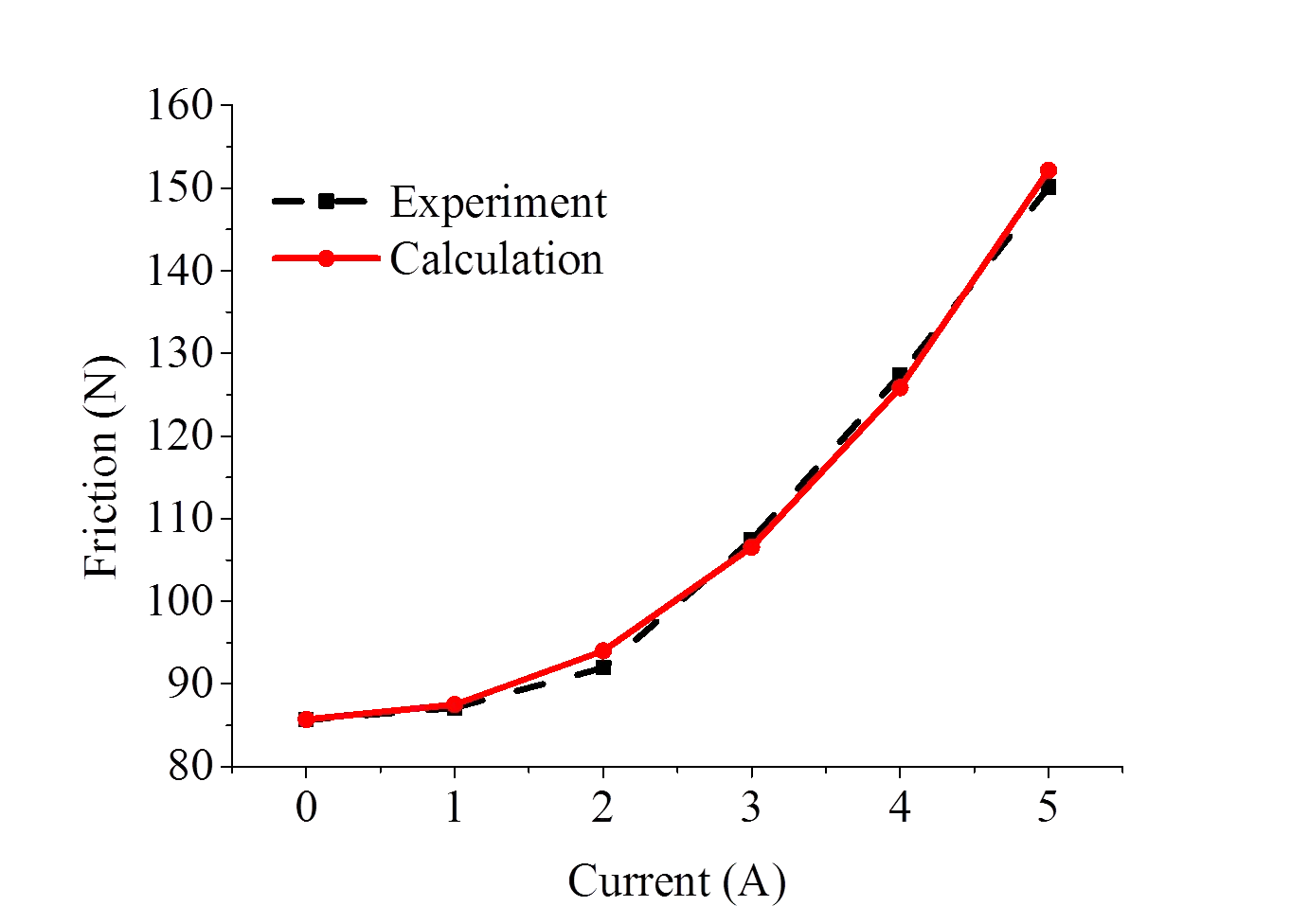
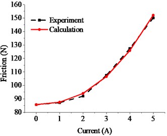
As , , and are hard to be obtained by experiment and theory, the parameters could be identified by the numerical method as shown in Table 2. The calculated friction forces are in good agreement with that by experiment as shown in Fig. 3. R-squared one reaches 0.9999.
Table 2Parameters for friction model
85.7 | 1.5 | 1.52 | 0.2 |
Fig. 2Experiment friction force when applied current is 0 A and 5 A
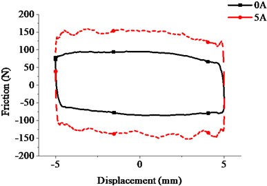
Fig. 3Friction forces by calculation VS by experiment
5. Conclusions
According to the experiment and analysis above, it should be believed that the friction force is nonlinear and enlarges along with the current applied to the piston coil. Friction force variation along with excitation velocity is not observed.
A novel friction model is proposed. Calculated friction forces with this model matches well with experiment. The model includes three parts which are the initial sliding friction force, current-related sliding friction force, and MR phenomenon-related friction force respectively. The pressure increment on the cylinder-piston surface and MR phenomenon in the MR fluid in a gap between cylinder and piston are the cause that the friction force enlarges along with the current which is applied to the piston coil.
References
-
Sohn J. W., Oh J. S., Choi S. B. Design and novel type of a magnetorheological damper featuring piston bypass hole. Smart Materials and Structures, Vol. 24, 2015, p. 35013.
-
Foister R. T., Nehl T. W., Kruckemeyer W. C., Raynauld O. Magnetorheological (MR) Piston Assembly with Primary and Secondary Channels to Improve MR Damper Force. U.S. Patent 20110100775 A1, 2011.
-
Hu W., Robinsonr, Norman W. A Design strategy for magnetorheological dampers using porous valves. Journal of Physics: Conference Series, Vol. 149, 2009, p. 12056.
-
Andrzej M., Miko H. Application of magnetorheological fluid in industrial shock absorbers. Mechanical Systems and Signal Processing, Vol. 28, 2012, p. 528-541.
-
Fernando D. G. Characterizing the Behavior of Magnetorheological Fluids at High Velocities and High Shear Rates. Ph.D. Thesis, Virginia Polytechnic Institute and State University, 2005.
-
Hu Z. D., Yan H., et al. Friction and wear of magnetorheological fluid under magnetic field. Wear Vols. 278-279, 2012, p. 48-52.
-
Vardarajan R. I., Alexander A. A. Wear testing of seals in magneto-rheological fluids. Tribology Transactions, Vol. 47, 2004, p. 23-28.
-
Zhao C. W., Peng X. H., Huang J. An enhanced dipole model based micro-macro description for constitutive behavior of MRFs. CMC: Computers, Materials and Continua, Vol. 30, Issue 3, 2012, p. 219-236.
About this article

We acknowledge the support from the Industry-university-research foundation of Guangzhou city (Project No. 201604016109).
