Abstract
The authors have been making a multi degree of freedom piezoelectric actuator that has Translational and Rotational motions in one joint (TR motor). Because the motor has the advantages such as simple structure and excellent controllability, it has high potentials for wide use in non-industrial applications. The authors will apply it to outdoor use, especially, use in water. The authors have applied insulating process to the piezoelectric element for waterproof and designed an optimal shape of it for driving in water to show driving TR motor in water successfully.
1. Introduction
The authors have made multi degree of freedom motor (translational and rotational motion in one joint, TR motor) by ultrasonic technology [1-3]. This motor has attractive features, that is, TR movements independently or simultaneously, easy to make a micro motor and high controllability. It has high potential of usage in unconventional field such as medical device, space actuator and robotic actuator of out field. In this research, the authors focus on the applications in water and have designed it.
2. Drive model of TR motor
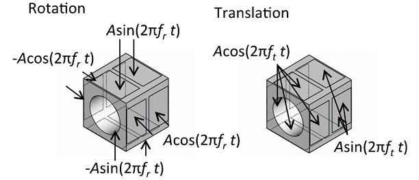
TR motor is made of two parts, a stator and rotator (Fig. 1). The stator has a through-hole of a rectangular metallic solid. Piezoelectric ceramics are pasted on each side of the stator. The operator applies alternative voltage to the ceramics at the resonant frequency. In this motor, three resonant vibration modes are used; one mode is for rotational movement (R mode) and two modes (T1 and T2 mode) are combined for translational movement [4-6].
Fig. 1Overview of TR motor
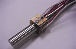
Applying voltages to the ceramics, the surface of the hole generates elastic vibration that transfers energy to the shaft by frictional contact.
R mode is a vibrational mode characterized by three nodes around the surface of the hole’s circle as shown in Fig. 2. It produces a traveling wave to go along the surface, at the top of which the frictional force is transmitted from the stator to the output shaft.
T1 and T2 modes are 1st and 2nd order axial modes of vibration as shown in Fig. 3. The TR motor uses these two modes for translation at the same frequency. When stator is cubic shape, the T1 and T2 modes are generated at the same or very near frequencies. For this reason, when an operator has applied one resonant frequency of voltage, two modes are generated and it produces translational movement.
There are two control parameters of the motor; frequencies and phase differences of the applied voltages. In this research, the frequencies should be set to the resonant to obtain best performance. The operator controls phase differences of the applied voltages and controls rotational speed and the direction (Fig. 4).
Fig. 2Vibration mode of rotation
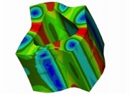
Fig. 3Vibration mode of translation
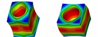
a) T1 vibration mode
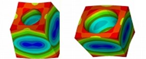
b) T2 vibration mode
Fig. 4Applied voltage
3. Waterproof ultrasonic motor
Generally speaking, the electrode of the piezoelectric ceramics is non-waterproof. In order to use in the water, electrode should be coated by water resist material. In this research the authors have applied three insulators: silicone rubber, poly vinyl resin (coating sprayer for electronic substrate) and epoxy putty (Fig. 5).
Fig. 5TR motors with Silicone rubber, Poly vinyl resin and Epoxy putty from the left
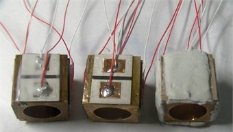
Silicone rubber has half fluidity by short time’s overheating and well gluing with metals. It has been used for sealant and protection and protective layer due to characteristics of heat resistance, waterproof and chemical resistance. Poly vinyl resin has electrical insulation, which is widely used for coating electrical circuits to keep moisture resistance and insulation. The authors have sprayed it on the electrode twice every 20 minutes. Epoxy putty has been widely used as gluing paste of two liquid mixing types. The main ingredient is epoxy resin which shows high gluing force, water resistance and easy to apply.
Since poly vinyl is spray type, the coating layer is thin. Silicone rubber and epoxy putty are pasted thick on the stators (Table 1).
First, the authors have evaluated the waterproof type stators in air. The results are shown in Table 2. It shows that maximum rotational velocity is reduced due to coating material to suppress the vibration.
Table 1Insultant thickness
Thickness [mm] | ||
Insulant | Silicone rubber | 0.20 |
Poly vinyl resin | 0.07 | |
Epoxy putty | 0.88 | |
Table 2Comparison of the velocities (ratio of with insultant and no insultant)
Rotation | Translation | ||
Insulant | Silicone rubber | 43 % | 52 % |
Polyvinyl resin | 60 % | 67 % | |
Epoxy putty | 47 % | 66 % | |
Secondly, the authors have made experiments in water and observed no rotational or translational movement. This is because there is a very thin water film between the stator and the rotor and it causes no driving force transmission from the stator to the rotor. In order to prevent the water film, the authors have improved the outer shape of the rotor by knurled.
The knurled has irregularity on the surface of the rotor and it is expected to inhibit the water film and help keeping firm contact with each other. The knurled has two types: parallel and diagonal.
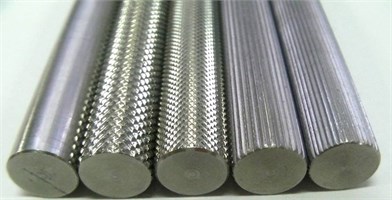
The authors have designed new type of the rotor as shown in Fig. 6.
(a) Normal shaft without knurled;
(b) Diagonal knurled shaft (pitch 1.0 mm);
(c) Parallel knurled shaft (pitch 1.0 mm);
(d) Diagonal knurled shaft (pitch 0.8 mm);
(e) Parallel knurled shaft (pitch 0.8 mm).
Shaft’s length 150 mm, diameter 9.98 mm, tolerance h8.
Fig. 6Normal and knurl shafts type. (a), (b), (c), (d), and (e) from the left
4. Experiments
Before trying to drive it in water, the authors have evaluated the new shafts in the air. The results are shown Fig. 7. Each shaft shows the same characteristics of velocity in the air as normal shaft. Next, the authors have evaluated these shafts (rotors) in water. In the experiment, the authors have obtained the results as follows:
1. The stator with epoxy putty cannot drive any types of shafts.
2. The parallel knurled shafts cannot be driven by any stators.
3. The stators with silicone rubber and polyvinyl resin can drive the diagonal knurled shafts.
Comparison of the velocity in the air and the water is shown in Table 4.
Fig. 7Frequency characteristics in water (Polyvinyl resin)
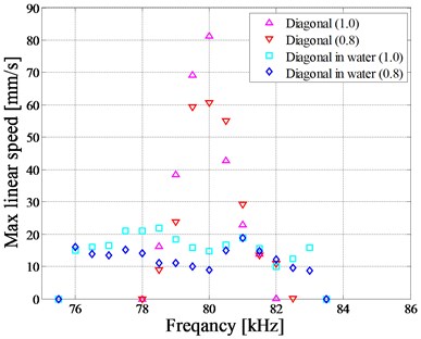
a) Max linear speed
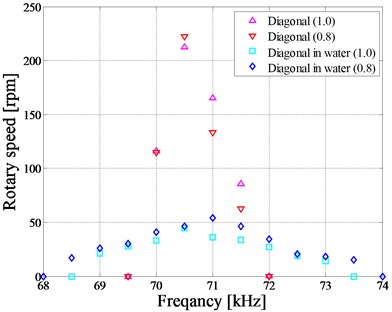
b) Rotary speed
Table 4Comparison of the velocities (ratio of in water and in air)
Knurl | Rotation | Translation | |
Silicone rubber | Diagonal (Pitch 1.0) | 20 % | 27 % |
Diagonal (Pitch 0.8) | 21 % | 31 % | |
Polyvinyl resin | Diagonal (Pitch 1.0) | 25 % | 34% |
Diagonal (Pitch 0.8) | 38 % | 31 % |
5. Conclusions
1) Applying silicone rubber and polyvinyl resin to the stators for waterproof and using diagonal knurled shaft, the authors can drive the TR motor in water successfully.
2) These TR motor can be driven in the air, but the velocity of the motors is reduced 20 percent comparing to that with no insulant.
References
-
Chen S., Mulgrew B., Grant P. M. A clustering technique for digital communications channel equalization using radial basis function networks. IEEE Transactions on Neural Networks, Vol. 4, 1993, p. 570-578.
-
Mashimo T., Toyama S. Development of the translational and rotational piezoelectric actuator using a single stator (1st report) – design of the stator by finite element method analysis. Journal of the Japan Society for Precision Engineering, Vol. 74, Issue 3, 2008, p. 292-297.
-
Ferreira P. A. M. High-performance load-adaptive speed control for ultrasonic motors. Journal of Control Engineering Practice, Vol. 6, Issue 1, 1998, p. 1-10.
-
Hoshina M., Mashimo T., Fukaya N., Matsubara O., Toyama S. Spherical ultrasonic motor drive system for pipe inspection. Advanced Robotics, Vol. 27, 2013.
-
Mashimo T., Toyama S. Vibration analysis of cubic rotary-linear piezoelectric actuator. IEEE Transactions on Ultrasonics, Ferroelectrics, and Frequency Control, Vol. 58, 2011, p. 844-847.
-
Mashimo T., Toyama S., Ishida H. Design and implementation of a spherical ultrasonic motor. IEEE Transactions on Ultrasonics, Ferroelectrics, and Frequency Control, Vol. 56, 2009, p. 2514-2521.
About this article

