Abstract
Traditional contact seal is usually used in rotating parts of ocean energy converters. It is hard to avoid leakage, and with the increase of working time, the leakage becomes serious, which will make ocean energy converters fail to work. In the paper, a new type isolation transmission mechanism, which is permanent magnetic coupling, replaces the traditional contact seal and achieves absolute seal of the rotating parts and longtime operation of ocean energy converters. This paper introduces permanent magnetic coupling into ocean energy converters and uses the equivalent magnetic charge theory to analyze the influence of magnet pole-pairs number on the transmitted torque of permanent magnetic coupling. The relationship between permanent magnetic coupling transmitted torque and magnet pole-pairs number is obtained. The paper is conducive to the promotion of using permanent magnetic coupling in ocean energy converters.
1. Introduction
With the increasingly serious global energy crisis, renewable energy has been gaining more and more attention, which is high-quality, clean, non-polluting and abundant. Ocean energy is the most abundant energy in renewable energy with advantages of high energy density and wide scope. The strategic and practical significances of ocean energy development are very important [1-6]. With decades of research, ocean energy has got tremendous development. Although there are still technical, cost and other issues, ocean energy is still the best way to solve the world's energy problems [7]. Using ocean energy to generate electricity is one form of ocean energy utilization, and many ways can be used to generate electricity from ocean energy, such as ocean wind energy, tidal energy, wave energy, ocean thermal energy and salinity gradient energy [8]. For most ocean energy converters, generating power from ocean energy mainly includes three stages, firstly converting the captured wave energy into mechanical energy, then converting the mechanical energy into rotating mechanical energy and finally converting the rotating mechanical energy into electricity [9]. Power generation efficiency and reliability are improved greatly with the rapid development of ocean energy converters in the past 30 years. However, many problems remain unresolved, such as low conversion efficiency, high maintenance cost, complicated hydraulic characteristics and long-term durability [10].
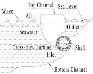
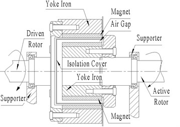
The wave energy converter shown in Fig. 1 is taken as a case in this paper. Energy conversion usually involves power transfer and the converters need to be isolated from the ocean water. The traditional contact seal, which is usually used in the past time, has many problems. Its power generation efficiency was very low and its start-up torque was very big. There exists serious water permeating, as shown in Fig. 2 and the transmission part is impossible to be completely sealed. Schematic diagram of wave energy converter in this paper is shown in Fig. 3.
To solve those problems, the permanent magnetic coupling with isolation cover is used to improve the transmission mechanism of the converters [11, 12]. This research introduces permanent magnetic coupling into ocean energy converters, which can further improve the equipment reliability with practicality. The permanent magnetic coupling, which is non-contact and flexible, can transmit torque without friction and mitigate wave pulsation. The isolation cover can seal completely and ensure the reliability and survivability of the converters.
Fig. 1Wave energy converters
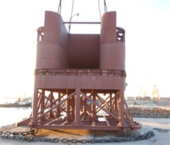
Fig. 2Water permeating

Fig. 3Schematic diagram of wave energy converter
2. Permanent magnetic coupling selection
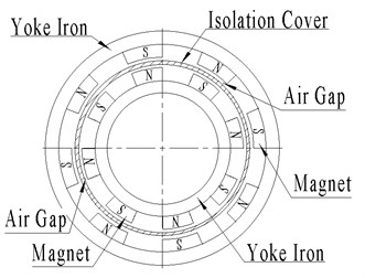
According to the layout of magnets, permanent magnetic coupling is divided into planar type as shown in Fig. 4 and concentric type as shown in Fig. 5. Concentric permanent magnetic coupling includes active rotor, driven rotor and isolation cover. Magnets are distributed on the inner surface of the driven rotor and the outer surface of the active rotor and the adjacent magnets have opposite polarity. Planar permanent magnetic coupling consists of two opposing rotors and magnets are distributed on the surface of the rotors. The opposite polarities face each other on different rotors and the pole-pairs are arranged along the circumferential direction. Planar permanent magnetic coupling is usually used in small power transmission occasions.
Fig. 4Planar permanent magnetic coupling
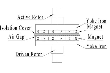
Fig. 5Concentric permanent magnetic coupling
The working principle of permanent magnetic coupling is unlike poles attracting each other but like poles repelling each other. Permanent magnetic coupling is a transmission mechanism using permanent magnetic driving technology and realizes non-contact and flexible transmission from power to load. It is especially suitable for occasions on which devices need to be isolated. Its transmission characteristic can be adjusted by controlling the parameters of the magnetic circuit. Permanent magnetic coupling achieves zero leakage without motive seals of traditional contact seal. It can be applied in bad environment with the advantages of small transmission vibration, no friction, overload protection and low noise. This paper designs a permanent magnetic coupling which is applied in ocean energy converters, as shown in Fig. 6.
Fig. 6Permanent magnetic coupling
3. Theoretical modeling
Methods to calculate the torque of permanent magnetic coupling are the equivalent current method, the equivalent magnetic charge method and some empirical equations [13, 14]. The equivalent current method calculates force between different magnets by calculating equivalent micro-current force of the magnetic field source. Some difficulties are unable to be overcame in complex 3D magnetic field. The equivalent magnetic charge method calculates force between different magnets by calculating equivalent magnetic charge unit force collected at the surface of the magnet and this method has good adaptability and high precision.
Fig. 7Magnets distribution
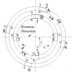
Fig. 8Spatial distribution of A and B
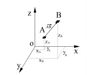
A four pole-pairs permanent magnetic coupling is shown in Fig. 7. The inner ring magnets are active magnetic poles distributed on the surface of the active rotor and the outer ring magnets are driven magnetic poles distributed on the surface of the driven rotor. Cartesian coordinate system is built in the center of permanent magnetic coupling, as shown in Fig. 7. Point A is on the magnet 2 and point B is on the magnet 1, as shown in Fig. 8. The point A coordinates are (), the point B coordinates are (), so the force between A and B is:
where , are the magnetic charges of point A and B, is magnetic media coefficient, is the vector from point A to point B:
Taking the coordinates of A and B into Eq. (1), can be expressed as:
The force between A and B is shown in Fig. 9.
Fig. 9The force between A and B
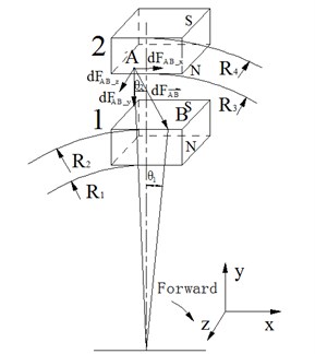
As shown in Fig. 9, the point A coordinates can be expressed as (), the point B coordinates can be expressed as (), so can be written as:
where , , are the components of the acting force between A and B in , , directions. The permanent magnetic coupling mainly transmits torque through the tangential force while the axial force has no effect on torque transmission. As shown in Fig. 9, the tangential force between A and B is:
The torque applied on point A is:
The torque on magnet 2 N-pole applied by magnet 1 S-pole is:
Eq. (6) is the torque that magnet 1 S-pole applies on the magnet 2 N-pole, and mark it as . Then other poles interaction torques , , can be got. So, the torque on magnet 2 that applied by magnet 1 is:
4. Numerical analysis
NdFe30 is selected as the magnetic material. Remanence magnetization is 1.044T. For magnets, length is 50 mm, width is 10 mm, thickness is 5 mm. Radiuses of permanent magnetic coupling are 23.5 mm, 28.5 mm, 34.5 mm, 39.5 mm. Air gap is 6 mm. Yoke iron is carbon steel. Assume that the yoke iron has no leakage, and magnetic induction intensity is distributed evenly. Following is the analysis of the magnetic transmitted torque performance.
The torque-angle characteristic curves of the permanent magnetic driver with different number of magnet pole-pairs are shown in Fig. 10.
Fig. 10Torque-Angle characteristic curves with different number of magnet pole-pairs
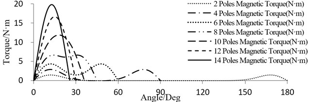
From Fig. 10, with the increase of magnet pole-pairs, maximum torque transmitted by permanent magnetic coupling becomes larger, the initial tangential angle of torque-angle characteristic curves increases gradually and permanent magnetic coupling rigidity becomes better. Besides, the angel between the adjacent magnets becomes smaller and magnetic field superposition becomes stronger. The maximum torque transmitted by permanent magnetic coupling is about 20 Nm in this case.
Permanent magnetic coupling can accommodate different number of pole-pairs with different magnet width, which will affect the torque permanent magnetic coupling transmits. The maximum torque transmitted by permanent magnetic coupling is shown in Fig. 11 with different magnet width.
Fig. 11Relationship between magnet width and torque
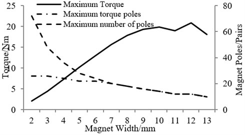
From Fig. 11, permanent magnetic coupling can accommodate more magnets when magnet width is small. However, the number of magnet pole-pairs required to transmit the maximum torque is not the maximum number that the coupling can accommodate with smallest magnet width. That means the more magnet pole-pairs are unfavorable for the transmitted torque of permanent magnetic coupling. When magnet width is large, the number of magnet pole-pairs required to transmit the maximum torque is equal to the maximum number that permanent magnetic coupling can accommodate. However, the maximum torque transmitted by permanent magnetic coupling does not always increase, and when magnet width reaches a certain value, the torque remains unchanged and even lower. The above analysis shows that the magnet width has an optimal value to get the maximum transmitted torque.
5. Conclusions
The paper introduces permanent magnetic coupling into ocean energy converters as a new type transmission mechanism and solves the sealing problem. The equivalent magnetic charge method is used to calculate the transmitted torque of permanent magnetic coupling. The transmitted torque characteristics of permanent magnetic coupling is analyzed.
By analysis, the torque transmitted by permanent magnetic coupling increases with magnet pole-pairs number increasing and torque transmission characteristics are improved as well. Magnet width has an optimal value to get the maximum transmitted torque for permanent magnetic coupling.
References
-
Zheng C. W., Li C. Y. Variation of the wave energy and significant wave height in the China Sea and adjacent waters. Renewable and Sustainable Energy Reviews, Vol. 43, 2015, p. 381-387.
-
Wu S., Liu C., Chen X. Offshore wave energy resource assessment in the East China Sea. Renewable Energy, Vol. 76, 2015, p. 628-636.
-
Rute Bento A., Martinho P., Guedes Soares C. Numerical modelling of the wave energy in Galway Bay. Renewable Energy, Vol. 78, 2015, p. 457-466.
-
Parkinson S. C. Integrating ocean wave energy at large-scales: a study of the US Pacific Northwest. Renewable Energy, Vol. 76, 2015, p. 551-559.
-
Behrens S. Wave energy for Australia’s national electricity market. Renewable Energy, Vol. 81, 2015, p. 685-693.
-
Astariz S., Iglesias G. The economics of wave energy: a review. Renewable and Sustainable Energy Reviews, Vol. 45, 2015, p. 397-408.
-
Zhang Xuechao, Li Xiangfeng, Shi Yufeng Ocean energy development present situation and prospects. Horizon of Science and Technology, Vol. 16, 2015, p. 258.
-
Zhao Weiguo, Liu Yutian, Zhang Weisheng Marine renewable energy power generation current situation and trend of development. Smart Power Network, Vol. 6, 2015, p. 493-499.
-
Wang Mingyu, Liu Dali, Ma Wenchao The design of the new type of wave energy power generation platform. Development and Innovation of Machinery and El, Vol. 3, 2015, p. 16-19.
-
Krasilnikov A. Y., Krasilnikov A. A. Magnetic clutches and magnetic systems in sealed machines. Chemical and Petroleum Engineering, Vol. 48, Issue 5, 2012, p. 306-310.
-
Wang Y.-L. A wave energy converter with magnetic gear. Ocean Engineering, Vol. 101, 2015, p. 101-108.
-
Markov D. V., Sobolev G. V., Frolov Y. I. Features of magnetic-clutch sealed chemical pumps. Chemical and Petroleum Engineering, Vol. 36, Issue 9, 2000, p. 552-557.
-
Krasil’nikov A. Y., Krasil’nikov A. A. Calculating the torque in an end magnetic clutch. Chemical and Petroleum Engineering, Vol. 41, Issue 7, 2005, p. 383-387.
-
Krasilnikov A. Y. Order of selection and design of magnetic clutches for sealed machines. Chemical and Petroleum Engineering, Vol. 49, Issue 7, 2013, p. 467-475.
About this article

The research was supported by the Fundamental Research Funds of Shandong University (Project No. 2016JC035) and the Natural Science Foundation of Shandong Province (Project No. ZR2016WH02), which are gratefully acknowledged.
