Abstract
In the current urban rail transit project in the vigorous development of the community, due to the needs of the site environment or line selection, it has been a common phenomenon in the actual construction of the tunnel encountered in the parallel operation and tunnel overlap situation, the new tunnel or tunnel group on the existing tunnel or other structure of the interaction problem has become very prominent! Based on the blasting excavation of the single-channel caverns in the first phase of the Chongqing Rail Transit Line 10 project, this paper makes a detailed investigation of the actual engineering, and uses ANSYS/LS-DYNA to simulate to comparative analysis and optimization the tunnel lining.
1. Introduction
Nowadays, the urban rail transit project is in the stage of vigorous development, but it’s quite common to encounter the parallel operation of the tunnel and the overlapping of the tunnel in the tunnel construction project by the restrictions of the site and the line. The problem of mutual interaction between a new tunnel and existing structures has become very prominent. In the parallel small clear distance and large cross section shallow tunnel group, the construction process, the safety construction section spacing, the influence of blasting vibration on the supporting structure, the reasonable timing of support has become an urgent problem to be solved.
The construction of underground caverns has attracted the attention of scholars at home and abroad, and put a lot of effort into the research. The research on the small-scale tunnels has yielded fruitful results [1-6]. In China, there are few studies on the construction technology of small horizontal tunnels with parallel holes of three holes and above, which mainly rely on very few concrete engineering examples.
According to the design summary of the 3-hole tunnel group of Yuexiu Park Station of Guangzhou Metro Line 2, Zhang Hongwei [7] has carried on the preliminary discussion on the construction of 3-hole tunnel scheme. Based on the combination of model test and finite element method, Wang Mingnian [8-9] studied the construction mechanics characteristics of 3-hole parallel tunnel with shallow buried and small spacing in weak surrounding rock. Guangzhou Metro Design and Research Institute [10] summarized the successful design and construction experience of Guangzhou Metro project, and provided technical guidance for similar projects in the future. Yang Hong she [11] also carried out in-depth analysis of the Guangzhou subway project, summed up the subway shallow buried hole construction process and key technology. Sun Zhongcheng [12] also combined with the project summed up the construction of the tunnel hole tunnel technology. In the study of the caverns, the study of blasting vibration and seismic effect is one of the focuses.
In summary, for more than 3 tunnels of single-channel tunnel group construction, reference experience needs to be studied and accumulated. Based on the engineering examples and the industry standard, this paper studies the blasting vibration of the parallel tunnel group in the five tunnels by combining the measured data of the field and the numerical simulation results. In order to obtain reasonable tunneling distance and support time, the mechanism of blasting vibration propagation in tunnel group is explored, which can provide reference for the safety and design of similar construction
2. Propagation effect analysis model of shock wave in group chamber
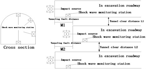
The main two main models of the shock wave propagation effect model of the shock wave generated by the blasting in the construction of the cavern group are the model of the dampness wave propagation attenuation model (Fig. 1) and the surrounding rock mass response model (Fig. 2). The former mainly studies the propagation vibration of the shock wave along the roadway in the surrounding rock medium during the tunneling process, and explores the construction of the single tunnel. The latter mainly studies the influence law of the vibration of the blasting vibration wave in the adjacent tunnel group, and qualitatively reveals the response characteristics of the surrounding rock of the different distance tunnel to the shock wave in order to arrange the longitudinal space of the construction.
Fig. 1Attenuation law of blasting seismic wave propagation models
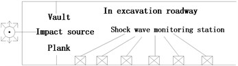
Fig. 2Shock response characteristics of surrounding rock of tunnel and Chambers model
3. Introduction to engineering
Yuelai station to Wangjiazhuang station interval and Wangjiazhuang parking lot entry and exit project is Chongqing Rail Transit Line 10 part of the project, the starting point for both Yuelai station, terminal for Wangjiazhuang station. The tunnel passes through the strata mainly sand and mudstone interbed, the surrounding rock level IV-VI level, the groundwater is bedrock fissure water. Wangjiazhuang parking lot entry and exit tunnel dome depth of 8.8-43.5 m, interval line tunnel dome depth of 4.8-40.1 m. The distance between the right and left of the line is 1.5 m, which is a small clear distance tunnel. The distance between the left line and the out-of-section structure is 3-6.5 m, which is a small-distance tunnel. The interval line set two contact channel, a channel construction. Due to the tight construction period, the construction land is limited, a single channel is used as the auxiliary channel construction, the left and right of the five independent channels, forming a unique single channel tunnel construction characteristics. Among them, the construction traffic organization is difficult, the ventilation pressure is big, the interaction crosses the big influence, especially the blast has the influence to the construction of the small clear distance tunnel.
4. Field test scheme design
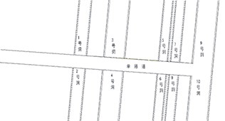
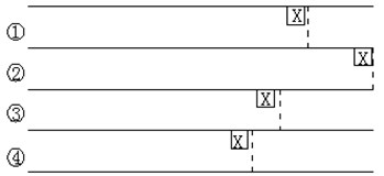
For the sake of generality, according to the blasting theory model and the existing experimental research results, arranged vibration equipment for testing in the 5, 6, 7, 9 tunnel. In the process of testing, considered the purpose and requirements of the test project, combined with the economic and effectiveness testing. The specific test results are shown in Fig. 3.
Fig. 3Schematic diagram of the original layout of horizontal tunnel test. Dotted lines represent constraints; digital number for the channel signal; X for test instrument
5. Test results
5.1. Longitudinal test results and analysis
Table 1 is the result of the peak value of the maximum vibration velocity of the longitudinal test, as can be seen from the table:
1) According to the measured data in Table 1, in the longitudinal direction of the tunnel, the more close to the working face of the maximum vibration velocity of vibration, with the increase of the distance from the explosion source center, the maximum vibration velocity of the subject is reduced, in accordance with the general law of blasting vibration.
Table 1Longitudinal test to maximum vibration velocity peak summary table
Tunnel | Instrument | Explosion source | Measuring point stake | Charge (kg) | Maximum peak velocity of each direction (cm/s) | ||
Longitudinal | Horizontal | Vertical | |||||
6 | 1 | RCK 0+121 | +220 | 24 | –0.429 | –0.19 | –0.214 |
2 | +160 | <0.05 | 0.378 | 0.285 | |||
3 | +130 | 2.874 | 2.843 | 2.726 | |||
4 | +100 | 1.403 | 1.537 | 3.325 | |||
7 | 1 | RCK 0+760 | +700 | 124 | 1.823 | –1.335 | –2.129 |
2 | +715 | 8.907 | 11.287 | 9.141 | |||
3 | +675 | 0.447 | 0.428 | 1.073 | |||
4 | +650 | 0.669 | 0.455 | 0.89 | |||
6 | 1 | ZK 43+265 | +260 | 52 | 6.032 | –3.284 | 10.50 |
2 | +290 | 0.260 | 0.215 | 0.263 | |||
3 | +330 | 0.695 | 0.357 | 0.307 | |||
4 | +410 | 0.263 | 0.088 | 0.123 | |||
5 | 1 | ZK 43+984 | +925 | 96 | –2.234 | -0.99 | 1.089 |
2 | +900 | 0.619 | 0.263 | 0.958 | |||
4 | +850 | 1.628 | 0.636 | 0.598 | |||
5 | 1 | ZK 43+993 | +960 | 96 | 2.529 | –2.761 | 5.927 |
3 | +935 | 2.855 | 1.876 | 3.407 | |||
4 | +850 | 0.796 | 0.596 | 1.14 | |||
9 | 1 | YK 44+099 | +040 | 108 | –0.819 | 0.959 | –2.579 |
3 | +090 | 1.755 | 1.841 | 5.001 | |||
4 | 43+880 | 0.463 | 0.287 | 0.187 | |||
2) The vibration velocity of the measuring point has a very significant difference in three different directions of the space. Among them, the vibration velocity of the vertical direction is obviously larger than that of the horizontal direction, this is mainly due to the particle in the direction perpendicular to the surface of the media when the movement of the constraints of small, while the constraint in the direction along the surface is large. Therefore, the vibration velocity in the direction perpendicular to the surface of the medium is the key to the blasting vibration hazard control.
6. Transfer law analysis of numerical simulation and field test result
6.1. Model geometry boundary
According to the engineering geological investigation report of the tunnel and the design dimension of the tunnel, a three-dimensional numerical analysis model is established. The upper surface of the model is chosen according to the actual terrain size, and the left and right boundaries of the model are about 3 times the tunnel diameter. The left and right boundaries of the model are set as direction displacement constraints, the front and rear boundaries are set as direction displacement constraints, the upper boundary is free, and the lower boundary is set as direction displacement constraint.
6.2. Parameter selection
The physical and mechanical parameters of surrounding rock and supporting structure in simulation analysis are determined according to relevant specifications and tunnel design data, at the same time steel arch according to the principle of equal consideration, that is to improve the elastic modulus of shotcrete to replace the role of steel arch. The physical and mechanical parameters of surrounding rock and tunnel support structure are shown in Table 2.
Table 2Material physical and mechanical parameters
Material name | Elastic modulus (GPa) | Poisson’s ratio | Bulk density (KN/m3) | Thickness (mm) |
Surrounding rock | 3.6 | 0.32 | 22 | / |
Steel arches spray concrete | 29.5 | 0.2 | 25 | 250 |
Secondary lining | 33.5 | 0.2 | 25 | 600 |
6.3. The establishment and calculation result analysis of group hole model
5 hole and 7 hole dislocation 40 meters, 5 hole and 9 hole dislocation 30 meters, 7 holes and 9 holes dislocation 70 meters of the situation:
Fig. 4Excavation surface of each tunnel dislocation distance sketch
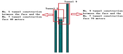
Under this condition, 5 tunnel face vault direction vibration velocity 33.12 cm/s, combined vibration velocity is 33.17 cm/s. No. 7 tunnel face vault direction vibration velocity 1.24 cm/s, combined vibration velocity is1.50 cm/s. No. 9 tunnel face vault direction vibration velocity 1.16 cm/s, combined vibration velocity is 1.21 cm/s. This can be seen when the dislocation of No. 5 tunnel and No. 7 tunnel face 40 m, No. 5 and No. 9 tunnel face dislocation 30 m. The 5 hole is the explosion source, No. 7 tunnel face vault direction of vibration speed and combined vibration speed meets the current national standard of newly poured concrete age 3 days allowed by the 3.0 cm/s velocity requirements, and No. 7 tunnel face vault direction of vibration speed and combined vibration speed meets the current national standard of newly poured concrete age 3 days allowed by the 3.0 cm/s velocity requirements.
6.4. Comparison chart of single hole measured trend chart and simulation under the condition of group tunnel simulation
As can be seen from Table 3, when the No. 5 tunnel and the blasting source have different longitudinal distance, the combined vibration velocity of the vault is different, when the distance of explosion source distance of 12 m, 28 m, 40 m, 48 m, 52 m, 68 m, 80 m, 92 m, 140 m, vault combined vibration velocity were 12.8 cm/s, 9.3 cm/s, 6.9 cm/s, 3.2 cm/s, 2.4 cm/s, 2.5 cm/s, 2.3 cm/s, 1.6 cm/s, 1.8 cm/s. It can be seen that the combination of the No. 5 number of the tunnel vault at the distance of the explosion source 48 m is 3.2 cm/s, more than the current national standard, but when the No. 5 tunnel vault distance explosion source 52 m, the combination of vibration velocity for the 2.4 cm/s to meet the engineering requirements.
From Table 3 can be drawn out of the vault combination speed trend chart 5. From the figure it is obvious that the trend of distance blasting source closer, vibration velocity increasing; blasting source distance farther, vibration velocity is small, there is a sharp drop in the middle process, after falling slowly. Taking into account the factors of blasting damage and other factors, the best distance of the two lining of the No. 5 tunnel should be about the distance from the explosion source 65 m, at this time, it can not only ensure that the impact of blasting on the two lining is in line with the requirements of the specification, but also can effectively make the two secondary lining construction operation, at this time of the second lining of the construction work distance is more reasonable.
Table 3No. 5 tunnel dome of the measured vibration value
Vibration velocity (cm/s) | 12.8 | 9.3 | 6.9 | 3.2 | 2.4 | 2.5 | 2.3 | 1.6 | 1.8 |
explosion source distance (m) | 12 | 28 | 40 | 48 | 52 | 68 | 80 | 92 | 140 |
Fig. 5Vault combination speed trend chart
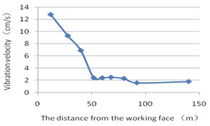
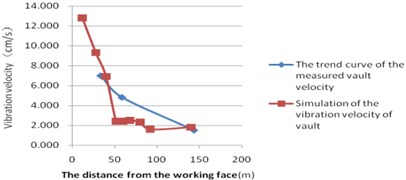
Fig. 6The trend chart of the combined vibration velocity of single tunnel vault
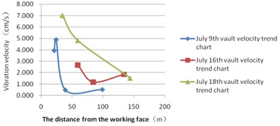
Fig. 7July 9, Field monitoring data and simulation data contrast trend chart
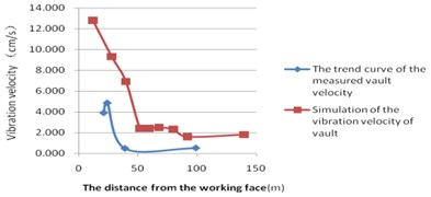
Can be seen from the Figs. 6-9, blasting seismic waves in the transmission process from the blasting source near the blasting seismic wave velocity sharp attenuation, the more distant regions tend to be gentle. In a certain total charge, charge structure, blasting pitch cases, the trend of simulated vault combination velocity is basically the same as the trend of measured vault, there is a certain error in the specific value. This is mainly to simulate the parameter selection and the actual situation there is a certain discrepancy, which is mainly the difference between the charge, simulation of the charge density and the actual blasting construction of the charge is different.
Fig. 8July 16, Field monitoring data and simulation data contrast trend chart
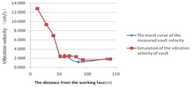
Fig. 9July 18, Field monitoring data and simulation data contrast trend chart
7. Conclusions
When blasting, the two lining is generally the new cast concrete, by the current national standard “blasting safety procedures GB6722-2014” article 13.2.2 of the provisions can be safely allowed to allow the value of 3 cm/s. The comparison of the simulation with the actual monitoring as well as the accumulation of the damage considered can be drawn: the secondary lining of the tunnel is about 65 meters away from the blast source and is generally safe, and basically meet the requirements of the specification. If the distance of the second lining is less than 65 meters away from the blast source, the combined vibration velocity of the tunnel dome is generally more than the specification requirements. This is disadvantageous for the second lining, so the second lining of the tunnel group is somewhat lagging behind. Should be a timely lining of the second operation, to meet the requirements of the second lining immediately.
References
-
Zheng Yuchao Three Holes Parallel Nearly by Shield Tunneling Effect Research. Southwest Jiaotong University, Chengdu, 2006.
-
Mi Decai The Stability of Surrounding Rock of Shallow Buried Large Span Cavern Group Engineering Geological Research. Chengdu University of Technology, Chengdu, 2006.
-
Jing Chunyan, Huang Hongwei, Zhang Zi-xin Dynamic monitoring and numerical simulation of small spacing tunnels construction analysis. Journal of Underground Space and Engineering, Vol. 3, Issue 3, 2007, p. 503-507.
-
Jiang Quan, Feng Xiating, Zhou Hui Screen deep secondary hydropower station diversion tunnel group allowed minimum distance study. Rock and Soil Mechanics, Vol. 29, Issue 3, 2008, p. 656-661.
-
Tang Jun-feng Large Hydropower Station Underground Cavities Construction Mechanical Behavior Research. Central South University, Changsha, 2010.
-
Sun Wenzhao Porous Tunnel Interaction Research. Dalian University of Technology, Dalian, 2012.
-
Zhang Hong-wei The design of Guangzhou metro station underground running tunnel of Yuexiu park to explore. Journal of Tunnel Construction, Vol. 21, 2001, p. 19-23.
-
Wang Mingnian, Li Zhi-ye, Guan Baoshu 3 shallow tunnel digging hole small spacing tunnel surface subsidence control technology research. Rock and Soil Mechanics, Vol. 23, Issue 6, 2002, p. 821-824.
-
Wang Mingnian, Li Zhi-ye, Liu Zhi-cheng 3 hole small spacing parallel shallow buried in weak rock tunnel construction mechanics study. Railway Construction Technology. Vol. 4, 2002, p. 11-14.
-
Small Spacing Porous Underground Running Tunnel Group of Integrated Technology. Design and Research Institute of Guangzhou Underground Railway, Guangzhou, 2004.
-
Yang Hongshe The subway construction process and key technology of shallow buried hole. Journal of Urban Rail Transit Research, Vol. 1, 2004, p. 70-72.
-
Sun Zhongcheng Connecting the small clear distance of hole in the tunnel construction technology. Railway Standard Design, Vol. 12, 2006, p. 66-69.
About this article

