Abstract
In order to solve the problem of near acoustic target location, vector hydrophone array with arbitrary formation is proposed to locate near field acoustic source. In this paper, firstly, the near field measurement model of vector hydrophone array is derived detailed. Then, introduces the conventional beamforming and MVDR algorithm based on vector hydrophone array. Finally, the performance of the algorithm is verified by simulation. The results show that the vector MVDR has higher target resolution, and the error decreases with the increase of SNR. It is more suitable for underwater near field regional warning.
1. Introduction
In recent years, with the rapid development of underwater robot technology, especially unmanned underwater vehicles (UUV) has the advantages of small volume, flexible applying, is often able to work at near area of the port or island, has become an important carrier to collect hydrological data and intelligence. The radiation noise of UUV is the most important target characteristic, and it is also the key signal of sensor array detection. However, with the application of new materials and noise reduction technology, the radiation noise level of UUV is getting lower and lower, so that it cannot be detected by acoustic sensor array in the distance. Therefore, it is more and more urgent to build a near field underwater warning system by using acoustic sensors array in the important islands or ports. At this point, the acoustic sensor is required to locate the target in a relatively near area, and then achieve the goal of damage.
In the near field of the acoustic sensor array, near field beamforming can obtain the searched spatial spectrum by searching the weights including azimuth and range parameters. The corresponding coordinates of the spatial spectrum’s peak are the location of the acoustic source target. Generally, the sensor array uses a uniform linear array, but in practice, position error is ineluctable, so it is necessary to study the beamforming algorithm under the near-field measurement model of arbitrary planar formation [1, 2]. Moreover, the vector hydrophone can simultaneously measure sound pressure and vibration velocity, and have larger data processing space compared with scalar acoustic pressure hydrophone [3, 4]. In this paper, the near field beamforming algorithm based on arbitrary planar formation vector hydrophone array is studied, which provides a new idea for the localization of acoustic source in near field, and is more suitable for practical application in Engineering.
2. Near field measurement model of vector array
In plane space, a sensor array consisting of arbitrarily arranged vector hydrophones, accepts the radiated noise signals of narrowband targets. For the sake of expression, the rectangular coordinate system is used to define the spatial position of each point. The first hydrophone is used as the coordinate origin to establish the coordinate system, and the space position of the array element and the target is shown in Fig. 1.
In the figure, the coordinate of the th vector hydrophone in the planar array is , 1, 2,…, . The coordinate of the th sound source is , 1, 2,…,. is the range between the sound source target and the origin, is azimuth, the angle between the positive direction of the axis, they are the parameters to be estimated. , defined as the th source’s range and azimuth relative to the th vector hydrophone.
The range between the th sensor to the th source can calculated:
Then the delayed phase relative to the reference origin can be expressed as:
So, the pressure signal of the th vector hydrophone can be expressed as:
In the above equation, , are the signal waveform, wave number of the th signal source. , are signal center frequency and sound field propagation speed. is the noise of the th vector hydrophone’s sound channel; is the number of sampling snapshots.
In the near field, the relationship between the acoustic pressure and the vibration velocity received by the vector hydrophone is quite complex, and no longer completely correlative. According to the Euler equation, the relationship between the vibration velocity and the acoustic pressure of a single two dimensional vector hydrophone can be expressed by following formula:
In the Eq. (4), are vibration velocity component of the th vector hydrophone. is near field acoustic impedance. , are respectively the direction cosine of the th sensor relative to the th target. are respectively the noise of the th vector hydrophone’s vibration velocity channel. In this paper, it is assumed that all channel noises are zero mean Gauss white noise, and are uncorrelated with the source signal. In isotropic environment noise, power satisfy the relation: , , , , are respectively noise power of sound pressure channel, vibration velocity component channels.
In Eq. (4), parameters can be obtained by the following formula:
In summary, , data matrix received by the two-dimensional vector hydrophone array can be written in the following form:
where, denotes Hadamard product; is -dimensional complex matrix, two-dimensional vector hydrophone array near field manifold matrix, and can be written as . is -dimensional complex matrix, near field manifold matrix of scalar sound pressure array, and can be written as:
where:
are correlation coefficient of sound pressure and vibration velocity component in different point.
Eq. (6) is the near field measurement model of vector hydrophone array. It can be seen that target location in near field can be converted to the estimation of , . In this paper, the near field beamforming algorithm is used to estimate the target parameters by the near field measurement model, so as to achieve the target’s position and improve the ability of underwater near field warning and defense.
3. The proposed algorithm
3.1. Near field vector conventional beamforming
The coordinate of the spatial spectrum peak can be regarded as the estimation of the target’s azimuth and distance. According to the near field measurement model of the vector hydrophone array, the output of the near field beamformer can be obtained:
where, , is weighting vector. , date vector received by hydrophone array. The output power spectrum of the array is:
where, , covariance matrix of sensor array’s output.
The coordinates of arbitrary point in plane space is , so weighting vector of each searched point is:
where:
is acoustic pressure steer vector. , are correlation coefficient of sound pressure and vibration velocity component at scanning point.
Therefore, the output spatial spectrum of the near field vector array by conventional beamformer is:
3.2. Near field vector MVDR beamforming
In order to obtain undistorted signal incident by the target sound source, and to minimize the total output power of the vector hydrophone array, it is can be used to restrain non target signals [5, 6]. Therefore, Capon proposed the MVDR beamformer, and the design of weighted vectors can be formulated as:
Under the constraint of minimum power, the optimal weight vector is obtained:
The output spatial power spectrums function of the near field vector MVDR beamformer is:
Through the Eqs. (9) and (12), it can be seen that the near field of hydrophone array is scanned by point by point, and spectrum of different points will be calculated, then the peak of spectrum is position of the target. In this paper, the vector beamforming algorithm will be used to locate the acoustic source target.
4. Simulation verification
In this section, the localization capability of arbitrary planar vector hydrophone array will be analyzed through the numerical simulation.
4.1. Simulation 1: Two target location capability analysis
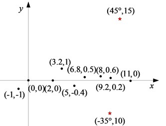
Assuming there are 2 independent sources in the plane space. The sound source’s frequency is 1480Hz, propagation speed is 1480 m/s, coordinates are (–40°, 10 m), (40°, 15 m). The sound pressure signal of the first hydrophone is used as the reference. The noise with signal-to-noise ratio (SNR) of 5dB is added. The vector hydrophone array coordinates are (0, 0), (–1, –1), (2, 0), (3.2, 1), (5, –0.4), (6.8, 0.5), (8, 0.6), (9.2, 0.2), (11, 0), the spatial position distribution is shown in Fig. 2.
Fig. 1Position of targets and array in near field
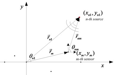
Fig. 2The distribution of dual source target in space
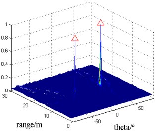
Near field vector conventional beamforming (denoted by VEC-CBF) and near field vector MVDR beamforming (denoted by VEC-MVDR) are used to calculate the spatial spectrum, and the normalized spatial spectrum is shown in Figs. 3-4.
In the figure, the position of red triangle is the real position of target. It can be seen that vector hydrophone array with arbitrary planar shape can locate the two sound sources by beamforming algorithm from simulation results in Fig. 3, Fig. 4. In contrast, VEC-MVDR algorithm’s main lobe is narrower than VEC-CBF algorithm’s, and the side lobe is also lower, and can locate the target accurately.
Fig. 3Sound source localization by VEC-CBF
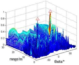
Fig. 4Sound source localization by VEC-MVDR
4.2. Simulation 2: Performance analysis of vector beamforming
In this paper, the peak’s coordinate is calculated by 100 Monte Carlo simulations, and the root mean square error (RMSE) is calculated by comparing with the real value. Consider a near-field acoustic source, the coordinates are (40°, 20 m), the SNR changes from –20 dB to 10 dB. Other parameters of the acoustic source and the sensor array are in accordance with the simulation 1. VEC-CBF, VEC-MVDR, scalar array conventional beamforming (denoted by SCA-CBF), scalar array MVDR (denoted by SCA-MVDR) are used to locate the target. The RMSE of azimuth and range estimators changed with SNR is shown in Figs. 5-6.
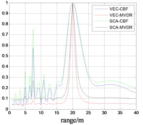
In order to better contrast the performance of the four kinds of algorithms, when the SNR = 0 dB, the average spatial spectrum is obtained by 100 Monte Carlo simulations. The sections along the azimuth and range parameters are shown in Fig. 7-8.
Fig. 5Azimuth estimator’s RMSE vs SNR
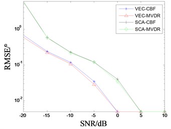
Fig. 6Range estimator’s RMSE vs SNR
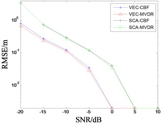
From Fig. 5 and Fig. 6, we can see that the RMSE of the four localization algorithms decreases with the increase of SNR when the number and position of hydrophones is the same condition. When the SNR ≥ 0 dB, the RMSE is almost zero and no longer changed. It also shows that four algorithms can all complete the near field target localization. Obviously, the RMSE of estimator obtained by two beamforming algorithms based on vector array are obviously smaller than that of scalar array beamforming algorithm, and the location accuracy is higher. Moreover, RMSE of azimuth and range estimated by MVDR algorithm is slightly smaller than conventional beamforming in the low SNR.
As you can see from Fig. 7 and Fig. 8, although the RMSE of the estimator is almost zero at SNR = 0 dB, the four methods can complete the target localization. However, the space spectrum’s main lobe based on VEC-MVDR is narrower, the side lobe is lower and the fluctuation is minimum. The SCA-CBF algorithm has the worst positioning performance. Therefore, the VEC-MVDR algorithm is more suitable for the localization of near field acoustic source targets.
Fig. 7Azimuth spectrum of target
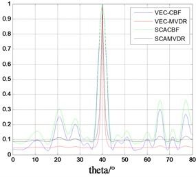
Fig. 8Range spectrum of target
5. Conclusions
In order to improve underwater near field defense capability of the key port and island, vector beamforming algorithm is proposed to locate underwater near field source targets. Firstly, simulation has been made to analyze the dual source localization by VES-CBF and VEC-MVDR algorithm. Simulation results show that VEC-MVDR has higher localization accuracy. In addition, the vector array beamforming and scalar array beamforming are compared and analyzed when they are used to estimate the azimuth and range. It is found that RMSE decreases as SNR increases. When the SNR ≥ 0 dB, the estimation error is close to zero. VEC-MVDR algorithm has the highest resolution, and is more suitable for underwater near field early warning defense than other algorithms.
References
-
Jie S., Yang D. S., Liu B. S., et al. Radiated noise sources near-field location based on MVDR focused beamforming. Journal of Dalian Maritime University, Vol. 34, Issue 3, 2008, p. 55-58.
-
Xiong Xin, Zhang Xin Hua, Lu Hai Jie A passive location method using minimum variance distortionless response focused beamforming for an arbitrary array. Applied Acoustics, Vol. 29, Issue 6, 2010, p. 471-474.
-
Shi Jie Near-Field High-Resolution Localization and Identification Method of Underwater Noise Sources Based on Vector Sensor Array. Harbin Engineering University, Harbin, 2009.
-
Yu Tong Kui The MVDR near-field based on vector sound pressure array. Ship Science and Technology, Vol. 34, Issue 6, 2012, p. 60-63.
-
Capon J. High-resolution frequency-wavenumber spectrum analysis. Proceedings of the IEEE, Vol. 57, Issue 8, 2005, p. 1408-1418.
-
Wang Chuan, Mei Ji Dan, Sun Lei Research on the passive location of near field using underwater acoustic image with MVDR focused beam-forming. Ocean Technology, Vol. 29, Issue 2, 2010, p. 56-59.
About this article

