Abstract
In this paper, the fault diagnosis method of Integrated Neural Network based on oil and Vibration information fusion is studied and applied to Aero-engine Fault Diagnosis. Then, taking an CFM56-3 Aero-engine as an example, the application of Integrated Neural Network Fault Diagnosis method in bearing fault diagnosis of Aero-engine is studied by using the idea of Vibration information and oil information Fusion Diagnosis, and the diagnosis method is validated with specific data. The diagnosis results show that compared with the traditional single information source Fault Diagnosis method, the integrated neural network Fault Diagnosis method is more efficient, can detect more fault modes, and has lower misdiagnosis rate.
Highlights
- The fault modes of integrated neural network diagnosis results are more than those of single diagnosis results.
- When the single diagnosis is contradictory, the diagnosis result of integrated neural network can solve the problem of diagnosis conflict well.
- Integrated neural network diagnosis can effectively reduce the misdiagnosis rate.
1. Introduction
Aero-engine, is a highly complex and sophisticated thermal machine, can provide the power required for flight engines for aircraft. As the heart of the aircraft, it is known as the “flower of industry”, and directly affects the performance, reliability and economy of the aircraft. It is an important manifestation of the strength of a country’s science, technology, industry and national defense. Because of the complex structure and various parts of Aero-engine, the fault diagnosis of Aero-engine has always been a difficult problem in the field of aero-intelligent maintenance.
At present, for a certain type of Aero-engine in the field of civil aviation, the main fault diagnosis methods are based on the lubricating oil information and vibration information [1]. Literature [2] puts forward the process neural network method, realizes the prediction of Aero-engine vibration trend. However, many faults of Aero-engine cannot be represented by a single information. It is necessary to integrate the information of various information sources in order to detect these faults. In order to solve these problems effectively, the integrated neural network diagnosis technology emerged as the times require. This paper studies the application of this method to Aero-engine fault diagnosis.
2. Integrated neural network diagnosis technology
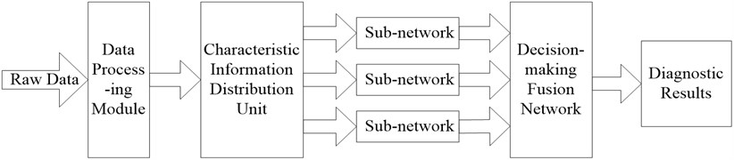
The diagnostic technology of integrated neural network is to process the information from different information sources. The feature vectors of the processed information are transmitted to the diagnostic sub-networks by the feature information allocation unit. After the diagnosis results of the sub-networks are obtained, the diagnostic results of the sub-networks are transmitted to the decision fusion network, and the final fusion diagnosis results are obtained [3]. This diagnostic technology can combine the advantages of oil information fault diagnosis method and vibration information fault diagnosis method, improve the accuracy of fault diagnosis, and discover the reason of using a single information source [4].
Barrier diagnosis is difficult to detect faults. The structure of the integrated neural network diagnosis system is shown in Fig. 1.
Fig. 1Structural diagram of integrated neural network diagnostic system
2.1. Data processing module
This module is based on the original data to specific filtering, feature selection and selection of a series of operations, the diagnostic network provides the feature vector for each for . By using this module, the filtering link can be started directly in the interface, and the data noise can be removed by filtering, so that the necessary data can be prepared automatically to the subsystem to ensure the operation of the diagnosis work. In addition to filtering, sample pretreatment can also be started through the interface to select the features of the selected parameters and prepare data for the training of the neural network [5].
2.2. Characteristic information allocation unit
The feature information distribution unit performs the task of assigning feature information to each diagnostic subnetwork. The distribution of feature information is determined by the structure of each diagnostic sub-network. The feature information allocated by each sub-network can be based on either a single parameter or multiple parameters. In the process of diagnosis, in order to achieve the optimal diagnosis results, feature information can be flexibly allocated according to training requirements, structure settings and expected results [6].
2.3. Diagnostic subnetwork
As the core of the whole diagnostic system, the diagnostic network consists of sub-networks responsible for diagnostic reasoning. Like rule-based expert system, diagnostic network includes two design parts: reasoning engine and knowledge base. It is only for diagnostic network. The reasoning mechanism adopted by inference engine has replaced the original reasoning based on symbolic rules by numerical calculation based on network structure, and the formation of knowledge base is also replaced by the learning and training of neural network [7].
If the diagnostic sub-network is allocated feature information based on multiple parameters, then assuming that the diagnostic confidence of n diagnostic parameters in the diagnostic sub-network for the same fault mode is , the diagnostic confidence of the diagnostic sub-network for the same fault mode is :
At the same time, the diagnostic input of the diagnostic sub-network based on multiple parameters can connect the eigenvectors of all diagnostic parameters and form a new eigenvector , . Usually, the three-layer network is used as the structure of each diagnosis sub-network, that is, the dimension of diagnostic input eigenvector is used as the number of input nodes, and the number of fault modes is used as the number of output nodes. In addition, the number of middle layer (hidden layer) nodes should be selected according to the training error requirement and the size of training sample set.
2.4. Decision fusion network
The principle of decision fusion network is to fuse the diagnostic conclusions of each diagnostic sub-network and make decisions.
Assuming that the integrated neural network diagnosis system diagnoses -type faults, each sub-network diagnoses -type faults based on its own characteristic information at the same time. The output of subnetwork is called fault mode vector:
The diagnostic results of each subnetwork for n-type faults are as follows [8]:
In the formula, is the diagnostic input eigenvector of function subnetwork ; is the mapping of the th subnetwork for the design of decision fusion network, which integrates the same nodes of each diagnostic subnetwork, that is, the diagnosis results of the same fault mode are fused by each diagnostic subnetwork, and finally a node is formed as the output of decision fusion network the final diagnosis result. If the diagnostic confidence of the th diagnostic subnetwork for -type faults is , then the fault mode matrix and the confidence weight matrix formed by the parallel combination of the m diagnostic subnetworks are respectively:
The output of decision fusion network is:
In the formula, represents the diagonal element. The diagnostic probability of the th fault is:
In the formula, 1, which is normalized, represents the contribution of each diagnostic subnetwork to fault diagnosis. It can be seen that the algebraic sum method can well reflect the role and influence of various factors in this synthesis.
3. Fault diagnosis of Aero-engine integrated neural network
3.1. Information preprocessing
The CFM56-3 Aero-engine is one of the world’s most classic engines, accounting for 55 % of the B737 aircraft. B737 aircraft has been widely used because it meets the needs of the market more closely in terms of range and efficiency. According to the actual application of CFM56-3 Aero-engine, this paper studies the integrated neural network diagnosis technology of Aero-engine Based on the fusion of lubricating oil information and vibration information. It is difficult to analyze and process the diagnostic data because of the difference in both numerical value and dimension. Therefore, before the fusion diagnosis, the original symptoms need to be preprocessed. The specific method is to compare the original data with the standard threshold values of various diagnostic methods. The definition in the normal range is 0, and vice versa is 1, so that the original symptoms data can be converted to 0 and 1.
According to the actual situation, the oil analysis mainly relies on spectral information because of the fewer ferrographic data of an Aero-engine. The concentrations of Fe, Cu, Mg, Al, Cr, Ni, Mo, Ti and Ag were selected as the original data for spectral diagnosis. After pretreatment, the diagnostic rules of spectral data are as follows: 1) Fe element concentration exceeding the standard (); 2) Cu element concentration exceeding the standard (); 3) Mg element concentration exceeding the standard (); 4) Al element concentration exceeding the standard (); 5) Cr element concentration exceeding the standard (); 6) Ni element concentration exceeding the standard (); 7) Mo element concentration exceeding the standard (); 8) Ti element concentration exceeding the standard (); Element concentration exceeded the standard ().
At present, there are many vibration parameters applied in engine condition monitoring, and the object and occasion of application will have a greater impact on the diagnostic effect of various parameters. In order to obtain the time domain characteristic parameters of engine vibration signal, this paper extracts the time domain signal based on the noise reduction of the vibration signal, and carries on the time domain statistical analysis. The data of excessive peak value () and excessive root mean square value () are selected as vibration data.
3.2. Integrated neural network diagnosis
The diagnostic system based on integrated neural network includes spectral information sub-network and vibration information sub-network. After pretreatment of various original symptoms, the Boolean value is obtained and used as the input of the sub-network. The output of each sub-network is the final failure mode. Taking engine rotor failure as an example, the failure modes are determined as follows: 1) normal system (); 2) bearing fatigue failure (); 3) bearing wear failure (); 4) gear gluing or scratch (); 5) gear overload fatigue ().
Fuzzy comprehensive decision-making method is used to make a comprehensive decision on the diagnostic results of each sub-network, so as to consult each sub-diagnostic network. Through the above diagnosis results of each sub-network, matrix can be formed, and the final comprehensive decision results can be obtained by multiplying matrix and weight matrix .
A Fuzzy Comprehensive Decision Model for:
In the matrix , , , , and are the diagnostic results of spectral information subnetwork, while , , , and are the diagnostic results of vibration information subnetwork. Weight matrix mainly measures the contribution of various diagnostic methods to different fault diagnosis.
According to the actual use of a certain type of engine and expert experience, the weights are determined as follows.
1) For “normal system ()”, the contribution of the two diagnostic methods is the same, that is, and are 0.5.
2) For “Bearing Fatigue Failure ()”, because vibration information has high reliability for the diagnosis of fatigue failure, it mainly relies on vibration information for diagnosis, so the weights of the two diagnostic methods are as follows: the weight of spectral information is 0.3, and the weight of vibration information is 0.7.
3) For bearing wear failure (), because the metal debris worn on the bearing surface is usually non-ferromagnetic particles and needs to be detected by spectroscopy, the weights of the two diagnostic methods are as follows: the weights of spectral information are 0.7, and the weights of vibration information are 0.3.
4) For “gear gluing or scratching ()”, because the spectrum can analyze the metal composition and content of gear wear. Vibration information contributes little to such faults, so the weights of the two diagnostic methods are: the weight of spectral information is 0.9, and the weight of vibration information is 0.1.
5) For “gear overload fatigue ()”, with fault 3, vibration information accounts for the largest proportion in this kind of fault diagnosis, so the weights of the two diagnostic methods are: spectral information weight is 0.3, vibration information weight is 0.7.
In summary, the weight matrix is:
Vector comprehensive decision results, is the final diagnosis results.
4. Examples
According to the flight parameters and lubricating oil data of an Aero-engine, the vibration value and lubricating oil data of a flight sortie are selected. The spectral data are shown in Table 1.
Table 1Spectral data
Element name | Concentration value / ppm | Element name | Concentration value / ppm |
Fe | 2.75 | Ni | 0.83 |
Cu | 3.60 | Mo | 1.01 |
Mg | 0.42 | Ti | 1.28 |
Al | 3.22 | Ag | 1.32 |
Cr | 2.75 | – | – |
Because there are too many points in the vibration data, only part of the vibration data are shown in this paper. The vibration data are shown in Table 2. The vibration peak value is 132.47 mm/s and the root mean square value is 20.463 mm/s.
Table 2Partial vibration data
Serial number | 1 | 2 | 3 | 4 | 5 | 6 | 7 | 8 | 9 |
Vibration value / mm.s-1 | 132.46 | 113.73 | 47.22 | 23.680 | 20.317 | 19.802 | 19.692 | 19.693 | 19.692 |
According to the vibration threshold value, abrasive concentration value and metal element concentration standard in the “Parameters and Processes of an Engine”, the comparative data analysis is as follows.
1) Spectral raw data. If chromium exceeds the standard and other elements are normal, the sign vector is (, , , , , , , , ) = (0, 1, 0, 0, 0, 0, 0, 0, 0).
2) Vibration raw data. If the peak value is too large and the root mean square value is normal, the symptom vector is (, ) = (1, 0). The diagnostic confidence of spectral subnetworks, vibration subnetworks and integrated neural networks is shown in Table 3.
Table 3Confidence in diagnosis of 3 diagnosis methods
Diagnostic method | Failure mode | ||||
Normal system | Bearing fatigue | Bearing wear | Gear scuffing and abrasion | Gear overload fatigue | |
Spectroscopic diagnosis | 0.0036 | 0.0025 | 0.3555 | 0.9125 | 0.5646 |
Vibration diagnosis | 0.346 | 0.9686 | 0.4540 | 0.0624 | 0.0080 |
Integrated neural network diagnosis | 0.0006 | 0.7650 | 0.6395 | 0.6655 | 0.0366 |
From Table 3 we can draw the following conclusions.
1) The fault modes of integrated neural network diagnosis results are more than those of single diagnosis results. For example, in the single spectrum diagnosis, only the “gear gluing and scratching” fault is diagnosed, in the single vibration diagnosis, only the “bearing fatigue” fault mode is diagnosed, while in the integrated neural network diagnosis, the fault mode is “bearing wear”, “bearing fatigue” and “gear gluing and scratching”. Obviously, integrated neural network diagnosis can find more faults than single diagnosis.
2) When the single diagnosis is contradictory, the diagnosis result of integrated neural network can solve the problem of diagnosis conflict well. For example, in the single spectrum diagnosis, the “gear gluing and scratching” fault is diagnosed with a confidence of 0.9123, while in the single vibration diagnosis, the “bearing fatigue” fault is diagnosed with a confidence of 0.9685. The diagnosis is contradictory. However, in the conclusion of the integrated neural network diagnosis, it can be seen that the problem of diagnosis conflict has been solved, and the “gear gluing and scratching” fault has been diagnosed at the same time. Injury fault (confidence 0.6654) and bearing fatigue fault (confidence 0.7652). Obviously, the integrated neural network diagnosis results are more reliable and accurate.
3) Integrated neural network diagnosis can effectively reduce the misdiagnosis rate. For example, the spectrum sub-network diagnoses the “gear overload fatigue” fault mode, but the fault is not detected in the conclusion of the integrated neural network diagnosis. Obviously, the misdiagnosis rate of integrated neural network diagnosis is lower.
5. Conclusions
In this paper, an integrated neural network diagnosis method based on oil information and vibration information fusion is studied and applied to bearing wear fault diagnosis of civil aviation CFM56-3 engine. The problem of low diagnostic efficiency and accuracy of aero-engine using single information source fault diagnosis method is solved. This method can also be applied to the diagnosis of other faults of aero-engine, which provides a new method for the fault diagnosis of aero-engine.
References
-
Wan Peng Research and Implementation of Flight Control Ground Fault Diagnosis System Based on Symptom Analysis. Ph.D. Thesis, University of Electronic Science and Technology, Chengdu, 2018.
-
Shi Xiangyang Research on fault diagnosis of B737 aircraft electric starting system based on BP neural network. Journal of Binzhou University, Vol. 12, Issue 6, 2018, p. 5-8.
-
Ling Yiqin Research on Fault Diagnosis Technology of Aircraft System Based on Fault Propagation Mechanism and Petri Net. Ph.D. Thesis, Nanjing University of Aeronautics and Astronautics, Nanjing, 2017.
-
Hao Yichuan Research on Fault Diagnosis Method of Aircraft Electronic System Based on Rough Set and Neural Network. Ph.D. Thesis, China Civil Aviation University, Tianjin, 2015.
-
Wang Hongwei Research on Key Technologies of Fault Diagnosis and Prediction for Rolling Bearing of Aero-engine. Ph.D. Thesis, Nanjing University of Aeronautics and Astronautics, Nanjing, 2015.
-
Deng Zheng Research on Aircraft Burst Fault Diagnosis Based on T-S Fuzzy Neural Network. Ph.D. Thesis, China Civil Aviation University, Tianjin, 2014.
-
Wu Wenjie Fault Diagnosis Method of Aero-Engine Based on Information Fusion. Ph.D. Thesis, University of Electronic Science and Technology of China, Chengdu, 2011.
-
Jin Xiangyang, Lin Lin, Zhong Shisheng Process neural network method for prediction of aero-engine vibration trend. Vibration, Testing and Diagnosis, Vol. 31, Issue 3, 2011, p. 331-334.
About this article

Project supported by National Natural Science Foundation of China, No. 51605037; Binzhou University Scientific Research Fund Project, No. BZXYG1705; Binzhou Soft Science Research Project, No. 2018BRK13.
