Abstract
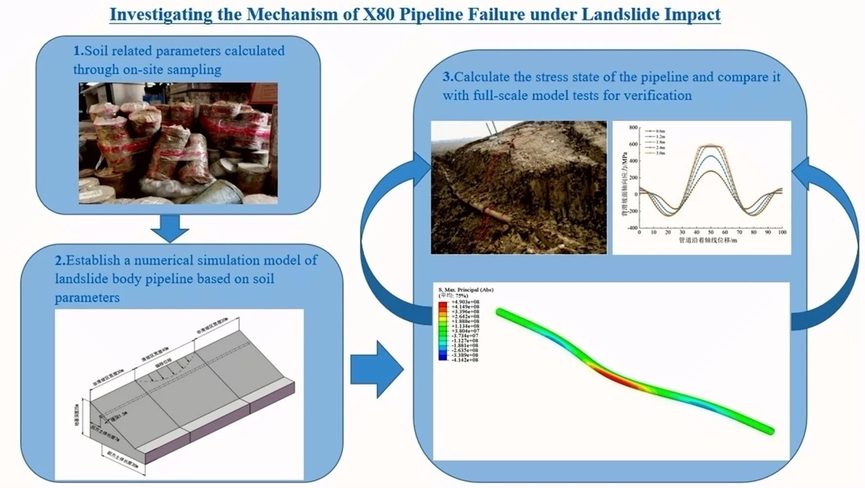
As energy demand continues to grow and environmental issues become more severe, the development and utilization of clean energy natural gas are becoming increasingly important. This paper focuses on the impact mechanism of landslide disasters on pipelines, analyzing how landslide displacement, width, pipeline wall thickness, and internal pressure affect pipeline stress and displacement. The study finds that landslides cause stress concentration at the middle and boundary positions of pipelines. As landslide displacement increases, pipeline stress also increases. For example, when landslide displacement is 1.2 meters, pipeline stress is approximately doubled compared to when the displacement is 0.6 meters. This research aims to explore the impact mechanism of landslide disasters on the stress response of natural gas X80 pipelines, with the goal of providing technical support for their stability and reliability.
Highlights
- The impact mechanism of landslide disasters on pipelines is investigated
- The study finds that landslides cause stress concentration at the middle and boundary positions of pipelines
- As landslide displacement increases, pipeline stress also increases
1. Introduction
Many regions in China experience frequent geological tectonic activities and intense natural geological processes, leading to frequent geological disasters, posing a significant challenge that urgently needs addressing [1-3]. Earthquakes often trigger numerous landslides due to unfavorable geological conditions, leading to significant casualties and property damage [4-6]. Pipeline projects often implement measures to avoid geological hazard-prone areas during design and construction. However, in certain special sections, due to factors such as urban and rural planning areas and environmentally sensitive zones, pipelines unavoidably pass through landslide-prone areas [7-8]. Landslide disasters can expose, suspend, or even rupture pipelines, potentially leading to environmental pollution, economic losses, and severe incidents such as fires or explosions [9]. Therefore, ensuring pipeline safety during landslides or ensuring continued operation through simple maintenance or monitoring is an urgent issue that needs to be addressed.
The study of the mechanical effects of landslides on pipelines began relatively late. Rajani (1995) [10] pioneered the use of analytical methods to investigate these effects, being the first to analyze the mechanical response of pipelines under lateral landslide forces using a simplified analytical approach. Magura (2012) [11] and others conducted additional stress measurement experiments on buried pipelines under axial and lateral landslide loads, comparing experimental results with numerical simulations. Chaudhuri (2020) [12] and others assumed a fourth-degree parabolic distribution of soil displacement, deriving displacement and deformation formulas for pipelines crossing landslides. They simplified pipeline deformation calculations under ground deformation by analyzing the influence of the pipe-soil interface on pipeline response. Once accidents occur, they can cause severe economic losses, environmental damage, and significant social impacts. For instance, the major landslide incident in Guangming New District, Shenzhen in 2015 resulted in a full-section rupture of the Second West-East Gas Pipeline, releasing high-pressure gas (delivery pressure approximately 3.8 MPa), leading to massive economic losses and casualties [13]. Therefore, investigating the stress response of landslides along the X80 pipeline, analyzing the pipeline’s behavior under landslide disasters, is crucial for ensuring the safe operation of the X80 pipeline.
2. Engineering geological modeling
The paper uses ABAQUS to model a landslide, simplifying it to a length of 100 meters based on its geometric characteristics and location. Fig. 1 shows the final model schematic. The model includes landslides and pipelines, with soil samples from Heilongjiang’s Heihe region, as depicted in Fig. 2. Mechanical parameters of the soil were obtained from shear and density tests, detailed in Table 1, while the X80 pipeline's physical parameters are based on previous studies, as shown in Table 2 [14].
Table 1Soil mechanics parameters
Soil | Density / kg/m³ | Elastic modulus / MPa | Poisson’s ratio | Cohesive strength / KPa | Internal friction angle / ° |
Slip zone | 1870 | 32.5 | 0.3 | 30.4 | 27.6 |
Stable zone | 1920 | 34 | 0.28 | 28.3 | 25.5 |
Table 2Pipeline mechanical parameters
Density / kg/m³ | Elastic modulus / GPa | Poisson’s ratio | Yield strength / MPa | Tensile strength / MPa | |
Pipeline | 8002 | 206 | 0.3 | 570 | 645 |
2.1. Application of landslide loads and boundary condition settings
This study aims to explore the factors affecting the stress sensitivity of pipelines to landslides. Displacement loads are applied to the rear soil, causing squeezing and sliding between the rear soil, pipelines, and front soil, simulating the pushing force exerted by the rear soil on the pipelines and front soil. This approach considers the obstructive effect of the front soil on both the pipelines and the rear soil, which is more reasonable compared to landslide forces. Based on previous research, assuming the soil displacement curve follows a Cosine function, with the pipeline axis defined as the -direction and the landslide movement as the -direction. The formula is as follows:
where: represents the displacement of soil perpendicular to the vertical pipeline axis, denotes the soil coordinate along the pipeline axis (with the origin at the pipeline center), stands for the width of the sliding zone, and , are constants to be determined [15]. This study aims to explore the sensitivity of various parameters of the X80 pipeline to stress concentration under landslide conditions. To control the magnitude of central landslide displacement conveniently, this experiment sets 1 and 0, as shown in Fig. 3 for the location and boundary conditions of the displacement load application.
2.2. Pipeline failure criteria
The failure criterion of the pipeline serves as a basis to determine whether the pipeline is in a safe or unsafe state. Due to its high-strength steel nature but low plasticity and toughness, the Von Mises criterion is applied to determine pipeline failure, as expressed in Eqs. (2-3). Failure is considered when the pipeline stress reaches the allowable stress, calculated to be 513 MPa [16]:
The principal stresses in three directions of a pipeline / MPa; pipeline yield stress / MPa; permissible stress of a pipeline / MPa; design factor or safety factor; weld joint design factor.
Fig. 1Schematic of finite element model
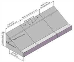
Fig. 2Field-sampled soil
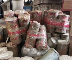
Fig. 3Landslide load and boundaries
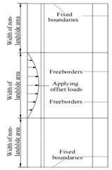
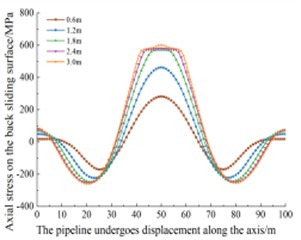
Fig. 4Axial stress of the pipeline
3. Analysis and results
This paper examines how pipelines fail under different landslide conditions to identify factors that affect stress concentration and displacement caused by landslides.
Fig. 4 shows the axial stress in the pipeline. The stress is highest at the center of the landslide and lowest about 25 meters from the center at both ends, forming a saddle shape. As the displacement of the landslide increases, the axial stress also increases, but at a decreasing rate. For example, when the displacement is 1.2 meters, the stress is about twice that at 0.6 meters. However, when the displacement is 2.4 meters, the stress only increases by 1 % compared to 1.8 meters. As the landslide displacement increases, the pipeline transitions from the elastic stage to the plastic stage. With further plastic deformation, the stress increase slows down while strain increases. Stress concentration in the pipeline mainly occurs at the center and the boundary of the landslide. Comparing the results from Fig. 6 (finite element simulation) and Fig. 6 [17] (full-scale test model), the results are quite consistent.
3.1. Response patterns under different landslide width conditions
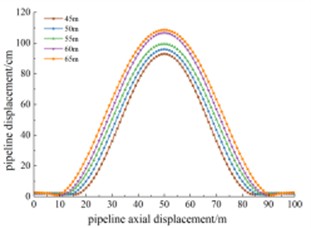
The landslide widths in the study area are set to 45 m, 50 m, 55 m, 60 m, and 65 m to explore the stress and displacement response of the pipeline under different landslide widths. Fig. 8 illustrates the Mises stress along the pipeline’s axial displacement under different landslide widths. As the landslide width increases, the length of the pipeline in the central section affected by landslide push increases, and the pipeline absorbs the resistance to soil through longer segments, thus slightly alleviating stress concentration. For example, when the landslide width is 45 m, the stress reaches 522.3 MPa (exceeding the allowable stress of 513 MPa, indicating pipeline failure), while at a width of 65 m, the stress is 367.8 MPa, showing an increase of approximately 42 %. Stress concentration peaks appear about 20 m from the central part of the pipeline, due to the boundary constraints of the landslide area causing the stress extremes to spread outward. For instance, with a landslide width of 45 m, the stress peak on both sides is about 266 MPa, compared to 236 MPa at a width of 65 m, showing only a 12.7 % increase. Fig. 9 shows the pipeline displacement values along its length under different landslide widths. The curves in the figure represent the distribution of pipeline displacement along its length for various landslide widths. Each displacement distribution curve resembles a normal distribution, with smaller displacements at the ends and larger displacements at the center of the landslide body. As the landslide width increases, the overall displacement of the pipeline also shows a gradual increase.
Fig. 5Numerical simulation of pipelines
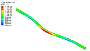
Fig. 6Full-scale testing [17]
![Full-scale testing [17]](https://static-01.extrica.com/articles/24306/24306-img6.jpg)
Fig. 7Mises stress at different slip widths
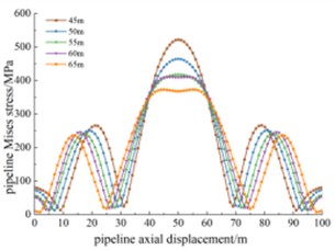
Fig. 8Displacement at different widths
3.2. Pipeline response patterns under different wall thickness conditions
The pipeline wall thicknesses in the study area are set to 18.4 mm, 21.4 mm, 25.7 mm, 30.8 mm, and 32.1 mm to investigate the stress and displacement responses under different wall thicknesses. Fig. 9 shows the Mises stress along the pipeline's axial displacement under different wall thicknesses. The stress distribution characteristics are similar, but the peak stress in the middle varies less with wall thickness. For example, with a wall thickness of 18.4 mm, the maximum Mises stress is 515.4 MPa (exceeding the allowable stress of 513 MPa and causing pipeline failure), while with a wall thickness of 21.4 mm, the maximum stress is 501 MPa, compared to 445 MPa with a wall thickness of 32.1 mm, showing increases of 15.8 % and 12.6 %, respectively. Fig. 10 shows the pipeline displacement along its length under different wall thicknesses. The displacement distribution characteristics are generally similar across the sections. However, between 40 m and 60 m of axial displacement, the pipeline displacement is inversely proportional to the wall thickness.
3.3. Pipeline response patterns under different internal pressure conditions
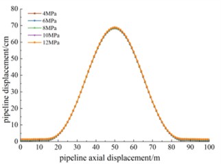
The internal pipeline pressures in the study area are set to 4 MPa, 6 MPa, 8 MPa, 10 MPa, and 12 MPa to investigate the stress and displacement responses under different pressures. Fig. 12 shows the Mises stress along the pipeline’s axial displacement under different internal pressures, with similar overall stress distribution characteristics. The internal pressure has less impact in the middle of the pipeline, where the effect of the landslide is more significant. For example, with an internal pressure of 12 MPa, the maximum stress is 474.4 MPa, compared to 450.8 MPa with 4 MPa pressure, showing only a 5.2 % increase. Fig. 13 shows the pipeline displacement values along its length under different internal pressures. The displacement distribution is generally similar, indicating that the landslide displacement has a larger impact on pipeline displacement than internal pressure during geological disasters.
Fig. 9Mises stress at different thicknesses
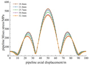
Fig. 10Displacement at varying thicknesses
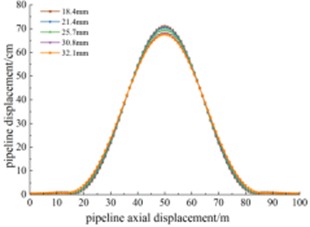
Fig. 11Mises stress at different pressures
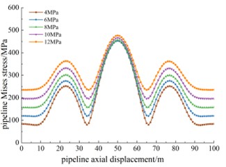
Fig. 12Displacement at varying pressures
4. Conclusions
The displacement of the landslide directly affects the pipeline’s stress and displacement. Research shows that as the landslide displacement increases, the axial stress also increases, with the greatest magnitude among all influencing factors. Pipeline stress is mainly concentrated at the landslide's central region and the pipeline junction, which are potential failure points that require special attention and reinforcement.
Landslide width is a significant parameter affecting pipeline stress concentration and displacement. Research indicates that as the landslide width increases, the pipeline's resistance to soil improves because a longer pipe section absorbs and dissipates the forces, slightly alleviating the stress concentration on the pipeline.
Different wall thicknesses and internal pressures are key parameters affecting pipeline stress concentration and displacement. That pipeline stress is inversely proportional to wall thickness and directly proportional to internal pressure, though the impact is relatively small.
References
-
S. Huang, Y. Lyu, H. Sha, and L. Xiu, “Seismic performance assessment of unsaturated soil slope in different groundwater levels,” Landslides, Vol. 18, No. 8, pp. 2813–2833, Apr. 2021, https://doi.org/10.1007/s10346-021-01674-w
-
S. Huang, Y. Lyu, Y. Peng, and M. Huang, “Analysis of factors influencing rockfall runout distance and prediction model based on an improved KNN algorithm,” IEEE Access, Vol. 7, pp. 66739–66752, Jan. 2019, https://doi.org/10.1109/access.2019.2917868
-
P. Pei, S. Huang, and J. Yuan, “Deformation and failure mechanism of overlying soil layers under strike-slip fault action,” (in Chinese), The Chinese Journal of Geological Hazard and Control, Vol. 35, No. 6, pp. 1–13, 2024.
-
S. Huang and C. Liu, “A computational framework for fluid-structure interaction with applications on stability evaluation of breakwater under combined tsunami-earthquake activity,” Computer-Aided Civil and Infrastructure Engineering, Vol. 38, No. 3, pp. 325–352, Jun. 2022, https://doi.org/10.1111/mice.12880
-
S. Huang and C. Liu, “Dynamic behavior analysis of bridge pier under impact of dam-break flood in different directions,” Natural Hazards, Vol. 120, No. 3, pp. 2705–2730, Dec. 2023, https://doi.org/10.1007/s11069-023-06301-6
-
S. Huang, Y. Lyu, L. Xiu, and H. Sha, “Seismic performance assessment of unsaturated soil slope indifferent groundwater levels,” Landslides, Vol. 18, pp. 2813–2833, 2021.
-
S. Huang, R. Tao, and R. Wang, “One simplified method for seismicstability analysis of an unsaturated slope considering seismic amplificationeffect,” Geological Journal, Vol. 58, No. 6, pp. 2388–2402, 2023.
-
S. H., C. Liu, and K. G., “Applicability of smooth particle hydrodynamics method to large sliding deformation of saturated slopes under earthquake action,” (in Chinese), Chinese Journal of Geotechnical Engineering, Vol. 45, No. 2, pp. 336–344, 2023.
-
L. Shujun, J. Ming, and Z. Weiming, “Magnetic memory detection of oil and gas pipeline defects based on BP neural network,” (in Chinese), Nondestructive Testing, Vol. 37, No. 7, pp. 25–28, 2015.
-
B. B. Rajani, P. K. Robertson, and N. R. Morgenstern, “Simplified design methods for pipelines subjected to transverse and longitudinal soil movements,” in Canadian Geo technical Journal, Vol. 32, pp. 309–323, 1995.
-
M. Magura and J. Brodniansky, “Experimental research of buried pipelines,” Procedia Engineering, Vol. 40, pp. 50–55, Jan. 2012, https://doi.org/10.1016/j.proeng.2012.07.054
-
C. H. Chaudhuri and D. Choudhury, “Buried pipeline subjected to seismic landslide: A simplified analytical solution,” Soil Dynamics and Earthquake Engineering, Vol. 134, p. 106155, Jul. 2020, https://doi.org/10.1016/j.soildyn.2020.106155
-
“Investigation report on the "12·20" Major landslide accident at the construction waste landfill in Guangdong Shenzhen Guangming New District,” (in Chinese), Chinese Journal of Emergency Management, Vol. 7, pp. 77–85, 2016.
-
N. Yang, M. Tingxia, and L. Weiyang, “Study on crack propagation in X80 pressure pipe based on ABAQUS,” (in Chinese), Journal of Plasticity Engineering, Vol. 25, No. 3, pp. 261–266, 2018.
-
J. Gao et al., “Prediction of limit landslide displacement based on pipe-soil interaction model,” (in Chinese), Science, Technology, and Engineering, Vol. 23, No. 11, 2023.
-
P. Zhang et al., “Limit width analysis of X80 corroded pipeline passing through landslide,” (in Chinese), The Chinese Journal of Geological Hazard and Control, Vol. 33, No. 4, pp. 47–54, 2022.
-
W. Feng, R. Huang, J. Liu, X. Xu, and M. Luo, “Large-scale field trial to explore landslide and pipeline interaction,” Soils and Foundations, Vol. 55, No. 6, pp. 1466–1473, Dec. 2015, https://doi.org/10.1016/j.sandf.2015.10.011
About this article

This work is financially supported by the National Key Research and Development Program of China (2022YFC3070100) and the National Natural Science Foundation of China (Grant No. 51708516).
The datasets generated during and/or analyzed during the current study are available from the corresponding author on reasonable request.
The authors declare that they have no conflict of interest.
