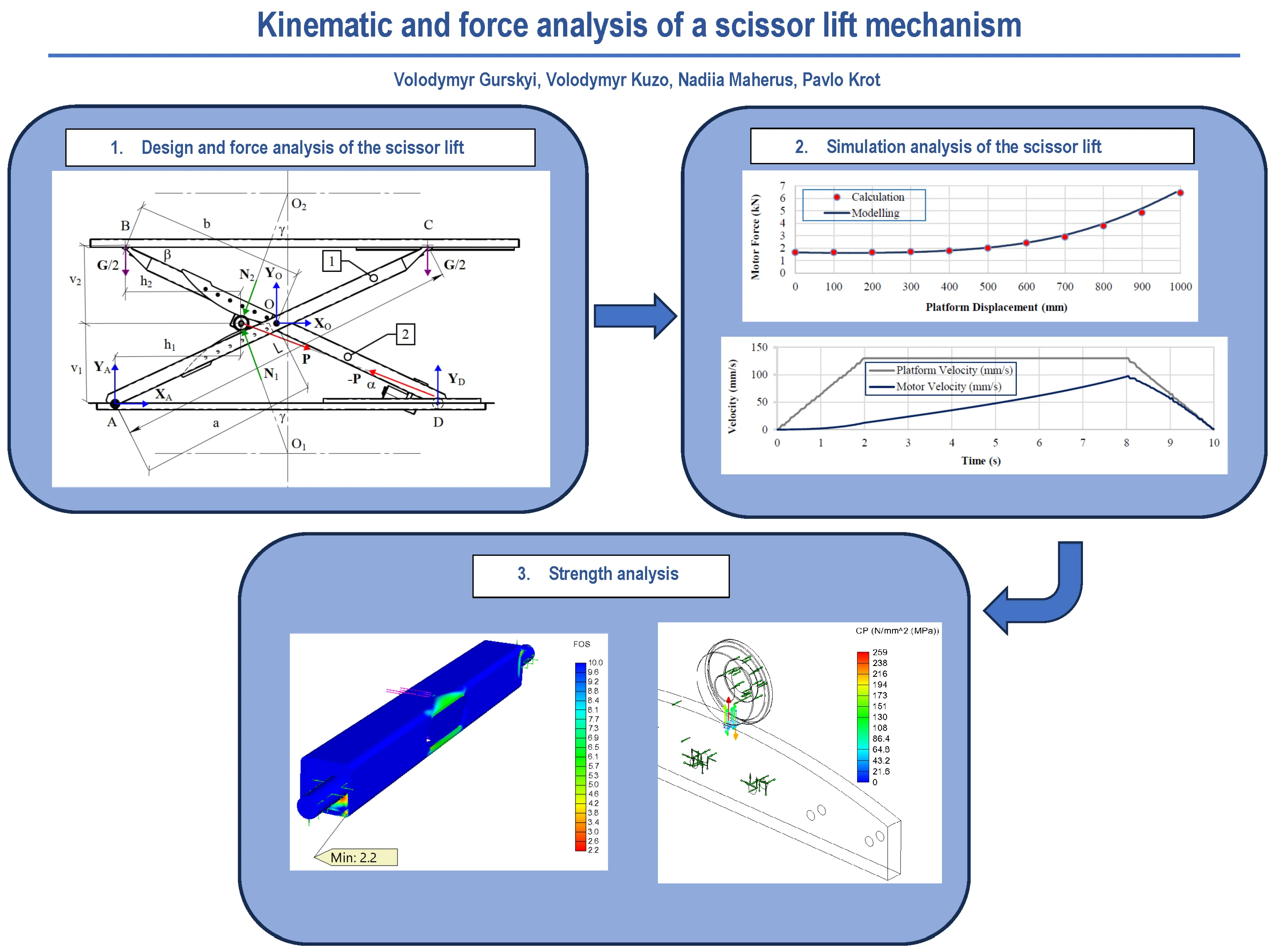
Abstract
A scissor lift design was developed with a load capacity of 100 kg and a lifting height of 1 m. The platform lifting mechanism is actuated by a traction electric motor via rollers moving along the guides. A calculation model of the scissor lift was created, resulting in a statically indeterminate system. Support reactions and an actuating force were determined depending on the platform lifting height. The analytical results showed that the actuating force increases nonlinearly during platform lifting, ranging from 1.674 kN to 6.45 kN, while the actuator rod stroke is 441 mm. Similarly, the simulation conducted using SolidWorks Motion yielded the actuating force in the range of 1.62 kN-6.5 kN and the rod stroke of 443.5 mm. The study established the patterns of variation of the main kinematic and force parameters of the scissor lift, which exhibit nonlinear characteristics. A piecewise linear variation of the actuating force was synthesized to ensure a trapezoidal motion profile of the platform. This type of motion profile was selected to provide comfortable and safe movement for people, particularly those with disabilities. The strength of the main structural elements of the scissor lift, namely levers, traction crossbar, guides and rollers, was ensured.
Highlights
- The design of a scissor lift with the roller drive, a load capacity of 100 kg, and a lifting height of 1000 mm is analyzed. A calculation model was developed, and the actuating force during platform lifting was analytically determined, varying within the range of 1.674-6.45 kN.
- A trapezoidal motion profile for the platform velocity was synthesized, requiring a piecewise-linear variation of the actuating force.
- Based on the simulation results, a strength analysis of the main structural elements was carried out.
1. Introduction
Parallel structure mechanisms provide high stiffness, accuracy, speed, and load capacity compared with serial mechanisms. They can be implemented using both rigid and compliant links [1, 2]. Such mechanisms possess unique properties that require a comprehensive kinematic, force, and dynamic analysis. These systems can be effectively investigated using modern CAD and CAE systems [2, 3]. Accordingly, scissor lifts are representative examples of such mechanisms.
Scissor lifts, similarly to other mechanisms with parallel structure, are widely used in various technical applications. They are primarily employed for vertical transportation of loads with lifting heights up to 20 m [4] and load capacities of 3.5 tons or more [5]. Experimental scissor-type mechanisms have also been developed for horizontal transportation [6] under the action of inertial forces [7], as well as for use as vibration isolators [8], [9]. The trends in the development of scissor lift drive configurations are reflected in a broader analysis [10], where the majority are linear drive systems based on hydraulic cylinders and roller screw mechanisms. Rope (belt) drive configurations also have certain advantages; however, their main disadvantage is the requirement for additional safety devices to secure the platform in case of rope or belt failure. A rather uncommon drive configuration was identified for the translational motion of the roller, which moves between two guides mounted directly on the levers [10]. This lifting mechanism configuration is employed by Lehner Lifttechnik GmbH. The linear drive is powered by a 24 V DC motor coupled with a ball screw, ensuring reliable platform retention in any position. Additionally, these systems can be designed to enable energy recuperation [11], [12]. For the same purpose, traditional hydraulic drives [13], [14], which have wider application, are being improved. In this respect, electrohydraulic systems are even more efficient [15]. The variety of scissor lift drive configurations forces design engineers to seek a trade-off between a gain in force and a gain in displacement.
Scissor lifts are safety-critical mechanisms and therefore require appropriate strength and deformation analysis. During operation, due to the change in the relative positions of the moving links, the actuating force and support reactions vary both in magnitude and direction. As a result, the structural elements experience a complex stress–strain state caused by the combined effects of bending moments, axial forces, and transverse forces on strength [16]. Therefore, the strength analysis of structural components should be performed for the link positions corresponding to the maximum load condition. In many cases, a static analysis is carried out when the platform is in its lowest and highest positions. For large-scale structures, stability issues may also occur, affecting both the entire structure [17] and individual elements under axial load [18], as well as under wind load [19]. For such structures, attention should also be paid to deformation and additional safety requirements [20], [21]. In cases where ensuring strength and stability requires significant design modifications, alternative solutions are proposed in terms of selecting rational structural parameters [22], determining the point of the actuating force application [23], and optimizing the design [24]. The implementation of modern topology optimization methods is becoming increasingly common [25]. The main objectives under consideration are aimed at reducing the overall weight, increasing rigidity, and minimizing the actuating force.
Researchers also use an integrated approach for a more comprehensive analysis [26]. Specifically, the use of multi-criteria optimization methods enables the development of an optimized design based on the main kinematic and force characteristics [27].
One of the key stages of the estimation process is establishing an analytical relationship between the actuating force and the lever inclination angle. A simple and accurate analytical solution is feasible only for a rather limited number of drive configurations [5], [13], [14]. Therefore, the wide variety of scissor lift designs and their drive configurations requires performing a set of calculation tasks, which mainly rely on the principles of statics, kinematics, and strength verification. However, the studies presented in the review do not sufficiently consider the issues of motion synthesis for the working platform intended for servicing people, especially those with disabilities.
2. Scissor lift design
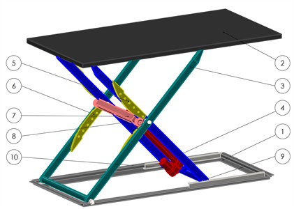
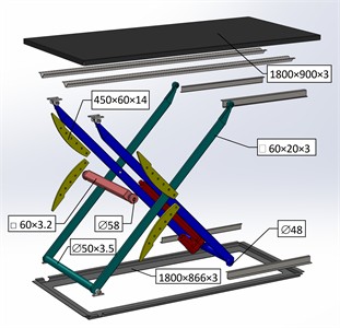
The scissor lift (Fig. 1) is designed according to the classical lever-type configuration, consisting of a pair of lifting levers attached to the fixed lower base (1) and the movable upper platform (2). The outer (3) and inner (4) levers are made from two longitudinal rectangular tubes welded together with a transverse round tube at the bottom. The inner lever is rigidly mounted at the top of the pantograph, and the outer lever at its bottom, through a hinged support. Guide plates (5) and (6) are mounted on the levers. The proposed pantograph design is based on the principle of actuating the scissor mechanism by applying a force between the levers through a traction crossbar (7). This crossbar is a welded structure made from a square tube. At the end faces of the crossbar, axles are welded, providing accommodation for pairs of guide rollers (8). These rollers run along the guides attached to the inner and outer levers, ensuring constant contact with no possibility of lateral displacement. The guides have a curved profile to maintain roller contact with their surfaces throughout the lifting and lowering process. A guide curved profile also contributes to reducing the actuator rod stroke. Support rollers (9) are mounted at the upper end of the inner lever and the lower end of the outer lever, running along flat sheet surfaces. A linear force from the drive motor (10) is applied to the crossbar, causing the rollers to open the levers while maintaining continuous contact along the guides. The upper platform is made from sheet material, which significantly reduces manufacturing costs. To increase rigidity, the upper platform is reinforced with perimeter-mounted flanges and welded longitudinal angle-section stiffeners. A similar approach is used for the lower base of the pantograph.
The following requirements were defined for the scissor lift design process:
1) Simplicity of structural design and minimal manufacturing costs due to the use of sheet metal and steel tubes [28] as the base elements for the main pantograph components (items 1, 2, 3, 4, 7).
2) The ability to adjust the lifting speed and height by using a high-efficiency DC motor (item 10) with substantial traction force as the drive. In addition, the scissor lift design can be powered by an autonomous power supply.
Fig. 1General view and main structural components of the scissor lift design: 1 – lower base; 2 – upper platform; 3, 4 – outer and inner levers; 5, 6 – guides; 7 – traction crossbar; 8 – guide roller; 9 – support roller; 10 – drive motor
3. Scissor lift calculation model and actuating force estimation
The scissor lift design calculation is based on forming the static equilibrium equations to determine the support reactions and the actuating force. The developed calculation model (Fig. 2) includes eight unknown force components, namely the reactions at the lower base , , ; the reactions at the central hinge , ; the normal reactions , ; and the linear actuator force , making the system statically indeterminate. The number of unknowns can be reduced by two by expressing the normal reactions , in terms of the actuating force . Thus, the total number of equilibrium equations becomes sufficient for solving the system.
Fig. 2Force analysis diagram of the scissor lift
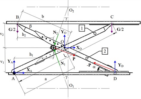
In the force analysis diagram, the following notations are used, namely is the angle between the line of action of the actuating force and the horizontal; is the angle between the line of action of the normal reactions and and the vertical; is the inclination angle of the levers relative to the horizontal; , are the distances from the attachment points of the outer and inner levers to the central hinge; is the length of the levers; , are the distances from the lower attachment point of the outer lever to the roller axle; , are the distances from the upper attachment point of the inner lever to the roller axle.
The normal contact reactions between the rollers and the guides are determined using the following equation:
For determining the unknowns, three equilibrium equations are established for each lever [26].
Lever 1:
Lever 2 (taking into account that the reaction at the central hinge O is directed oppositely):
After substituting Eq. (1) into systems of Eqs. (2) and (3), a system of linear equations is obtained for the unknown vector, which is computed using the matrix approach:
where is the matrix of coefficients for the unknown parameters:
and is the vector of the right-hand sides of the linear equations:
The analytical expressions for the unknown variables are rather cumbersome; therefore, numerical values will be used. For this purpose, the scissor lift geometric parameters were determined as a function of the current platform height (Table 1). The extreme platform positions and the corresponding geometric parameters are shown in Fig. 3.
Fig. 3Geometric parameters of the scissor lift
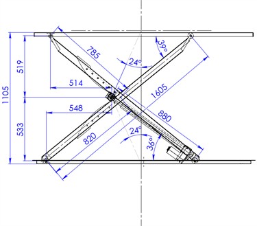
a) Upper position
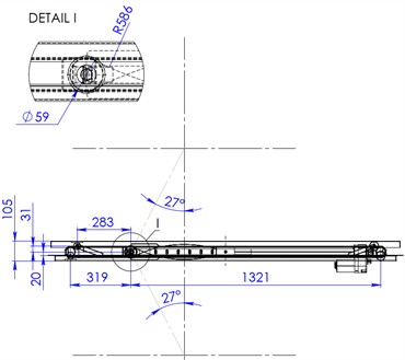
b) Lower position
The actuator rod stroke required to lift the platform to a height of 1000 mm is 1321–880 = 441 mm, which indicates a trade-off with a gain in displacement.
Table 1Geometric parameters of the scissor lift
(mm) | (deg) | (mm) | (kN) | |||||
0 100 200 300 400 500 600 700 800 900 1000 | 0 2 5 8 11 14 18 22 26 31 36 | 0 4 7 11 15 18 22 26 30 35 39 | 27 25 22 20 18 17 17 17 19 21 24 | 20 72 123 174 226 277 328 379 430 482 533 | 31 80 129 177 226 275 324 373 421 470 519 | 319 376 429 478 520 553 576 587 586 573 548 | 283 340 393 441 483 516 539 551 550 538 514 | 1.674 1.673 1.675 1.724 1.790 2.020 2.427 2.907 3.795 4.863 6.450 |
For the extreme lower and upper platform positions, the calculated parameters have the following values:
The linear actuating force varies within the range of 1.674-6.45 kN, reaching its maximum value at the upper platform position.
The maximum normal forces Eq. (1) acting on the pair of rollers at the upper platform position are 8.49 kN; 4.34 kN.
4. Simulation analysis of the scissor lift using SolidWorks Motion
The main purpose of the simulation analysis is to verify the mechanical and kinematic characteristics of the scissor lift obtained in the preliminary calculation.
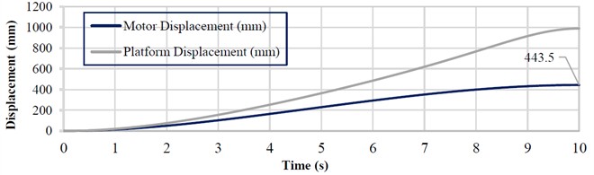
The initial conditions for the simulation are as follows: lifting height of the platform is 1000 mm; simulation time is 10 s; the mass of structural elements is neglected; platform load is 1 kN. The time dependencies of the main force and kinematic parameters are presented in Fig. 4. All the dependencies exhibit a nonlinear behavior.
The time-dependent variation curves shown in Fig. 4, a makes it possible to determine the required type of drive, taking into account the maximum actuating force and power demand. The actuating force must be at least 6.5 kN, and the power consumption of the drive must be no less than 250 W. The drive employs a 24 V DC traction linear actuator (model D24C05A5‑20M0NH‑DEE) with a maximum actuating force of 11.35 kN and a rod stroke of . The rod speed varies within the range of 32-54 mm/s. The actuator is based on a roller screw with a self-locking lead screw, ensuring self-braking and reliable platform retention in any position. For the selected actuator, its power is approximately 400 W.
According to the simulation analysis, the normal reaction forces and also reach their maximum values in the upper position of the platform, amounting to 8.65 kN and 4.46 kN, respectively (Fig. 4(b)). The deviation between the analytical and simulation results is 1.89 % and 2.76 %.
The maximum linear displacement of the actuator rod required to lift the platform to the specified height is set to 443 mm (Fig. 4(c)). This value does not exceed the rated maximum rod stroke.
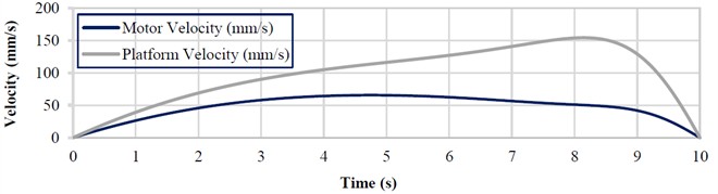
The average lifting speed of the platform, according to the initial conditions, is 0.1 m/s, while the instantaneous peak speeds during the motion (Fig. 4(d)) reach 0.154 m/s for the platform and 0.0656 m/s for the actuator rod. However, the actuator-rod speed exceeds the capability of the selected actuator. Therefore, in practice, the actual lifting time of the platform will be longer than the 10 s specified in the simulation. Based on the main force, energy, and geometric characteristics, the selected actuator is sufficient for driving the scissor lift under consideration.
Due to the original drive configuration, the actuator rod is subjected only to axial loads. The rollers and the guides experience the highest loading. The loads from the guides are transmitted to the levers, and the inner lever additionally receives the load from the linear actuator at its mounting point.
Based on the simulation results, the following points have been confirmed:
1) The maximum actuating force of the linear drive occurs in the upper position of the platform.
2) The adequacy and applicability of the selected drive type have been verified.
3) The applied roller screw drive configuration presents a trade-off, providing a 2.25-fold gain in displacement at the expense of a 6.45-fold reduction in force.
Fig. 4Time-dependent variation curves of the main force and kinematic characteristics of the scissor lift
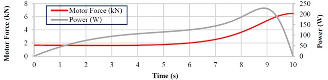
а)
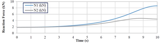
b)
c)
d)
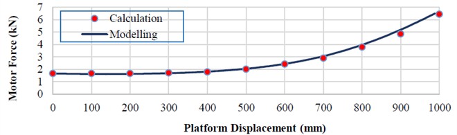
Based on the obtained time-dependent variations, additional functional characteristics can be derived. Among them, the variation of the actuating force with respect to the platform lifting height is of practical interest. Fig. 5 presents the results of both simulation and analytical calculation (Table 1). The simulation showed that the actuating force during the platform lifting process increases from 1.62 kN to 6.5 kN. The error between the analytical and simulated results for the actuating force at the limit values does not exceed 3.2 %.
Fig. 5Variation of actuating force with platform displacement
Developing the motion profile for the platform is a typical task in the design process of lifting mechanisms. The implemented motion profile is sufficient for lifting cargo, tools, and equipment. For the transportation of people, however, it is advisable to synthesize a motion profile that meets safety and comfort requirements.
To reduce dynamic loads in the structural elements, it is advisable for the platform to move at a constant speed 0.13 m/s for most of the time, which is achieved by limiting the maximum acceleration during the transient phases. The acceleration and deceleration times of the platform are assumed to be equal and denoted as 2 s. The time during which the platform moves at a constant speed is denoted as 6 s. The total motion time of the platform is 10 s (Fig. 6).
Fig. 6Simulated velocity profiles for the platform and actuator rod
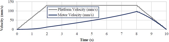
Based on the simulation results, the following patterns can be identified, and certain assumptions can be made:
1) The actuator rod speed reaches its maximum value at time .
2) The velocity profile of the actuator rod can be approximated as linear over all time intervals.
3) The linear motor velocity is lower than the platform velocity.
These patterns make it possible to simplify the control of platform motion.
5. Strength analysis of the main structural elements
For most scissor lift designs, ensuring structural integrity primarily depends on verifying the strength of the main elements, namely scissor levers, axles, brackets, and crossbars. This verification can be performed analytically by constructing internal force diagrams [30] and subsequently checking the strength. Many researchers also utilize the capabilities of computer-based modeling [31]. The key parameter for strength evaluation is the factor of safety (FOS).
According to the general load scheme of the scissor lift, the stress–strain state of the main functional components was analyzed using the finite element method. The analysis was carried out for the upper platform position, where the actuating force reaches its maximum value. Fig. 7 shows the simulation results values of FOS for the outer lever, inner lever, and traction crossbar. The inner lever is subjected to higher loading compared with the outer lever due to the direct transmission of the actuating force from the linear actuator. Similarly, the load from the actuator is transferred to the traction crossbar, which is additionally loaded by the transverse forces arising from the contact between the roller and the guide. The strength of the analyzed structural elements meets the normative requirements of the standard, ensuring the operability of the scissor lift. The simulation results are also presented in Table 2.
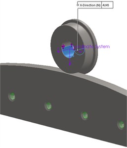
One of the key functional elements of the scissor lift design is the roller that runs between two guides. The geometric parameters of the guide and roller are shown in Fig. 8. According to [7], the guide geometric dimensions influence the kinematic characteristics and the power of the scissor lift drive.
The calculated value of the contact force is 4.25 kN, since the base calculation model is planar (Fig. 9(a)).
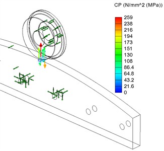
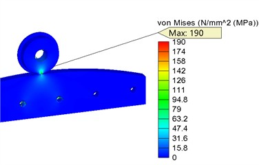
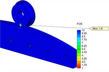
The finite element analysis (FEA) showed that the contact pressure is 259 MPa (Fig. 9(b)), von Mises stress is 190 MPa (Fig. 9(c)), while the minimum FOS for the contact element material (steel 1.0301) is 1.9 (Fig. 9(d)). The contact pressure value obtained from the simulation indicates the need for material heat treatment of the rollers in order to achieve a surface hardness of 180-220 HB and to increase the contact strength limit to 440-480 MPa. Thus, the condition ensures the contact strength of the roller surface.
Fig. 7FOS analysis results
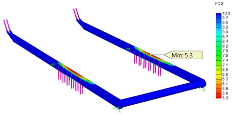
a) Outer lever
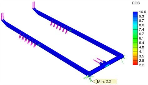
b) Inner lever
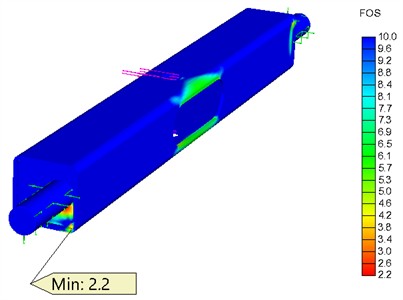
c) Traction crossbar
A similar verification was performed for other structural elements. Based on the preliminary calculations, the design parameters were refined to comply with the standard FOS requirement, as scissor lift structures must satisfy 2.0 [32], [33]. The design modifications proposed for the scissor lift included increasing the wall thickness of the rolled steel elements and enlarging the axle diameters. The FEA results for the main structural elements are presented in Table 2.
The design documentation for manufacturing the scissor lift was developed. The estimated weight of the lift is approximately 115 kg (excluding fastening elements).
Fig. 8Geometric parameters of the contact interface between the guide (1) and the roller (2)
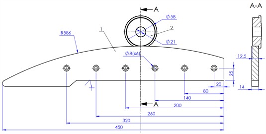
Fig. 9Strength analysis results
a) Loading scheme
b) Contact pressure
c) Von Mises stress
d) FOS
Table 2Calculated FOS for main structural elements of the scissor lift
Structural element | Details | Material (DIN) | Load | FOS | |
Designation | Value, kN | ||||
Outer lever | Profile 60×20×3 Tube Ø50×3.5 | 1.0301 (С10) | 0.5 | 5.3 | |
8.49 | |||||
Inner lever | 0.5 | 2.2 | |||
6.45 | |||||
4.34 | |||||
Traction crossbar | Profile 60×3.2 Axle Ø25 | 1.0503 (С45) | 6.45 | 2.2 | |
Roller | Ø58 | 1.0301 (С10) | 2.13 | 1.9 | |
6. Conclusions
The design of a scissor lift with the roller drive, a load capacity of 100 kg, and a lifting height of 1000 mm is analyzed. A calculation model was developed, and the actuating force during platform lifting was analytically determined, varying within the range of 1.674-6.45 kN. SolidWorks Motion simulation showed the patterns of variation of the main kinematic and force parameters of the platform and the drive. The actuating force increases nonlinearly, reaching values of 1.62-6.5 kN, which confirms the validity of the analytical calculation for statically determinate positions.
A trapezoidal motion profile for the platform velocity was synthesized, requiring a piecewise-linear variation of the actuating force. This type of motion profile is essential for mechanisms that provide accessibility for people with disabilities, ensuring comfort and safety during lifting operations.
Based on the simulation results, a strength analysis of the main structural elements was carried out. Structurally weak areas were identified, and design modifications were implemented to ensure compliance with the standard FOS requirement ( 2.0).
The main structural modifications introduced relative to the original scissor lift configuration are listed below. The wall thickness of the levers increased from 2 mm to 3 mm, and the wall thickness of the traction crossbar increased from 3 mm to 3.2 mm. For the contact components, namely the roller and the guide, a higher-grade steel, 1.0402 (C20), should be used.
References
-
S. Sollapur, P. Waghmare, and H. Adarsha, “Design and experimental investigation of XY compliant mechanism for precision applications,” ECS Transactions, Vol. 107, No. 1, pp. 4967–4976, Apr. 2022, https://doi.org/10.1149/10701.4967ecst
-
D. D. Baviskar, A. S. Rao, S. Sollapur, and P. P. Raut, “Designing a piezo-actuated four-bar motion amplification mechanism for enhanced compliance,” in Lecture Notes in Mechanical Engineering, Singapore: Springer Nature Singapore, 2025, pp. 95–105, https://doi.org/10.1007/978-981-97-5621-6_8
-
S. Sollapur, M. S. Patil, K. Chaporkar, A. Misal, R. Bhoyar, and K. Dhole, “Design and development of constrain based XY flexural mechanism,” in Techno-Societal 2018, pp. 267–273, Nov. 2019, https://doi.org/10.1007/978-3-030-16962-6_27
-
T. Hongyu and Z. Ziyi, “Design and simulation based on Pro/E for a hydraulic lift platform in scissors type,” Procedia Engineering, Vol. 16, pp. 772–781, Jan. 2011, https://doi.org/10.1016/j.proeng.2011.08.1153
-
M. Čuchor, Kučera, and M. Dzimko, “Engineering design of lifting device weighing up to 3.5 tons,” Transportation Research Procedia, Vol. 55, pp. 621–628, Jan. 2021, https://doi.org/10.1016/j.trpro.2021.07.095
-
V. Korendiy and O. Kachur, “Locomotion characteristics of a wheeled vibration-driven robot with an enhanced pantograph-type suspension,” Frontiers in Robotics and AI, Vol. 10, Aug. 2023, https://doi.org/10.3389/frobt.2023.1239137
-
V. Korendiy, P. Krot, O. Kachur, and V. Gurskyi, “Analyzing the locomotion conditions of a wheeled vibration-driven system with a V-shaped suspension,” in Lecture Notes in Mechanical Engineering, Cham: Springer Nature Switzerland, 2024, pp. 153–163, https://doi.org/10.1007/978-3-031-63720-9_14
-
C. Cheng, S. Li, and Y. Wang, “Modeling and analysis of a high-static-low-dynamic stiffness vibration isolator with experimental investigation,” Journal of Vibroengineering, Vol. 20, No. 4, pp. 1566–1578, Jun. 2018, https://doi.org/10.21595/jve.2017.18643
-
K. Ghaedi, Z. Ibrahim, H. Adeli, and A. Javanmardi, “Invited review: recent developments in vibration control of building and bridge structures,” Journal of Vibroengineering, Vol. 19, No. 5, pp. 3564–3580, Aug. 2017, https://doi.org/10.21595/jve.2017.18900
-
A. Corrado, W. Polini, L. Canale, and C. Cavaliere, “To design a belt drive scissor lifting table,” International Journal of Engineering and Technology, Vol. 8, pp. 515–525, 2016.
-
V. Zakharov, Stawiński, T. Minav, and A. Kosucki, “Energy harvesting analysis of an electrified scissor lift,” in 18th Scandinavian International Conference on Fluid Power, 2023.
-
L. Stawiński, V. Zakharov, A. Kosucki, and T. Minav, “Electromechanical actuator-based solution for a scissor lift,” Actuators, Vol. 12, No. 10, p. 394, Oct. 2023, https://doi.org/10.3390/act12100394
-
V. Paramasivam, S. Tilahun, A. Kerebih Jembere, and S. K. Selvaraj, “Analytical investigation of hydraulic scissor lift for modular industrial plants in ethiopia,” Materials Today: Proceedings, Vol. 46, pp. 7596–7601, Jan. 2021, https://doi.org/10.1016/j.matpr.2021.01.838
-
M. Čuchor, Kučera, and M. Lukáč, “Design of vehicle lifting equipment using progressive methods,” LOGI – Scientific Journal on Transport and Logistics, Vol. 12, No. 1, pp. 238–248, Jan. 2021, https://doi.org/10.2478/logi-2021-0022
-
L. Stawinski, J. Zaczynski, A. Morawiec, J. Skowronska, and A. Kosucki, “Energy consumption structure and its improvement of low-lifting capacity scissor lift,” Energies, Vol. 14, No. 5, p. 1366, Mar. 2021, https://doi.org/10.3390/en14051366
-
X. Yu, Y. Ji, W. Wang, S. Cheng, and W. Xu, “Static performances of scissor structures,” Structures, Vol. 65, p. 106684, Jul. 2024, https://doi.org/10.1016/j.istruc.2024.106684
-
A. Seidakhmet et al., “Research of kinematics and dynamics of the lever lifting mechanism used in the mobile automotive lift,” Applied Sciences, Vol. 13, No. 20, p. 11361, Oct. 2023, https://doi.org/10.3390/app132011361
-
S. Jasim, “A study on the static stability of scissor lift,” AACE Clinical Case Reports, Vol. 7, 2021.
-
M. Augustyn, M. Barski, M. Chwał, and A. Stawiarski, “Numerical and experimental determination of the wind speed value causing catastrophe of the scissor lift,” Applied Sciences, Vol. 13, No. 6, p. 3528, Mar. 2023, https://doi.org/10.3390/app13063528
-
H. Rashid et al., “Design review of scissors lifts structure for commercial aircraft ground support equipment using finite element analysis,” Procedia Engineering, Vol. 41, pp. 1696–1701, Jan. 2012, https://doi.org/10.1016/j.proeng.2012.07.370
-
R. G. Dong et al., “An investigation on the dynamic stability of scissor lift,” Open Journal of Safety Science and Technology, Vol. 2, No. 1, pp. 8–15, Jan. 2012, https://doi.org/10.4236/ojsst.2012.21002
-
A.-T. Dang, D.-N. Nguyen, and D.-H. Nguyen, “A study of scissor lifts using parameter design,” in Advances in Engineering Research and Application, pp. 75–85, Nov. 2020, https://doi.org/10.1007/978-3-030-64719-3_10
-
J. Wu, H. Li, P. Hu, P. Yuan, B. Jiang, and A. W. Tiako Youani, “Simulation and optimization of scissors mechanism of electric charging bow,” in Advances in Transdisciplinary Engineering, IOS Press, 2024, pp. 523–532, https://doi.org/10.3233/atde231144
-
L. Solazzi, “Lightening the scissor lift platform using composite material,” AIAS 2024, Vol. 85, No. 1, Feb. 2025, https://doi.org/10.3390/engproc2025085009
-
G. Arunkumar, R. Kartheeshwaran, and S. J., “Investigation on design, analysis and topological optimization of hydraulic scissor lift,” in Journal of Physics: Conference Series, Vol. 2054, No. 1, p. 012081, Oct. 2021, https://doi.org/10.1088/1742-6596/2054/1/012081
-
N. Vukojević, A. Talić-Čikmiš, and K. Šabanović, “Kinetostatic and stress analysis of scissor lift,” in Machine and Industrial Design in Mechanical Engineering, pp. 374–382, Jan. 2025, https://doi.org/10.1007/978-3-031-80512-7_37
-
N. H. Linh et al., “Application of MCDM method in selection of schema for optimal design of double scissor lift tables,” in Advances in Engineering Research and Application, pp. 244–253, Dec. 2022, https://doi.org/10.1007/978-3-031-22200-9_26
-
L. V. Sanches, C. A. Goulart, P. A. B. Maclean, and L. A. Villas-Boas, “Mechanical analysis and materials selection of a scissor lift system for pig transportation,” Acta Scientiarum. Technology, Vol. 46, No. 1, p. e65406, Feb. 2024, https://doi.org/10.4025/actascitechnol.v46i1.65406
-
A.-T. Dang and T. T. N. Nguyen, “Investigation on the design of double-stage scissor lifts based on parametric dimension technique,” Machines, Vol. 11, No. 7, p. 684, Jun. 2023, https://doi.org/10.3390/machines11070684
-
T. Dang, “Application of a numerical method in analyzing the operation of single-stage scissor lifts,” Rakenteiden Mekaniikka, Vol. 57, No. 3, pp. 126–137, Nov. 2024, https://doi.org/10.23998/rm.146410
-
C. Görkem Dengiz, M. Can Şenel, K. Yıldızlı, and E. Koç, “Design and analysis of scissor lifting system by using finite elements method,” Universal Journal of Materials Science, Vol. 6, No. 2, pp. 58–63, Mar. 2018, https://doi.org/10.13189/ujms.2018.060202
-
“Safety requirements for industrial scissors lifts,” Washington, ANSI MH29.1-2020, 2020.
-
R. A. Tatara, “Design and construction of a compact, portable, all-electric, 185-kg scissor lift,” Academic Journal of Manufacturing Engineering, Vol. 16, pp. 43–48, 2018.
About this article

The authors have not disclosed any funding.
The datasets generated during and/or analyzed during the current study are available from the corresponding author on reasonable request.
Volodymyr Gurskyi: conceptualization, methodology, supervision, writing-review and editing. Volodymyr Kuzo: investigation, resources. Nadiia Maherus: methodology, software, validation, visualization, writing-original draft preparation, writing-review and editing. Pavlo Krot: formal analysis, validation, writing - review and editing.
The authors declare that they have no conflict of interest.
