Abstract
This article entails a thorough investigation into the problems surrounding the maintenance of seismic stability of the subgrades of railways when an earthquake occurs. The seismic impact on the soil layers of the subgrade produced horizontal inertial forces, distribution of which by height, and their impact on the overall stability of the structure were assessed with the help of calculation formulas. The results of the calculations suggest that it is necessary to increase safety in designing road systems in seismic areas, strengthen weak areas, and choose the best design options. Theoretical methods have been worked out and suggested on how to compute the best variant of the slopes to avoid different types of deformations of the railway track in the area of the seismically active zone. Accepting seismic coefficient in the upper and lower section of the earthwork has been established using a graph, which is based on the type of soils and slopes.
1. Introduction
Earthquakes take one of the leading positions among other natural cataclysms because of the destructive power of their consequences, the magnitude of the number of victims, and damage to the human environment. Earthquakes cannot be stopped, but their destructive effect and the quantity of mortalities among people can be decreased by providing special anti-seismic, scientifically-grounded constructive solutions. Many investigations of the effects of destructive earthquakes in these or other parts of the roadways prove that factual data on structural deformations play the crucial role, and only thanks to them, the nature of the deformations may be recognized and, referring to the latter, the fundamental principles of the earthquake-resistant construction may be worked out [1-3].
The importance of scientific research that is devoted to the engineering analysis of different types of earthquake effects on the seismic resistance of buildings and road structures is enormous, with their assistance only it is possible to identify the types of deformation and, relying on the latter, to develop the principles of the construction of buildings and road construction that are resistant to earthquakes. The findings of studies on the seismic resistance of road structures, the behavior of road surfaces and special road structures during earthquakes and industrial explosions are given in the works by scientists A. Kh. Abdujabarov, T. Rashidov, V. F. Babkov and O. V. Andreev [4], [5].
2. Related work
The investigation of the aftermath of devastating earthquakes enabled determining the weaker points of railways and highways, when 15-20 % of the earth surface was devastated, rolling stock turned over and rails took on the shape of a complete circle, and pavement of roads and air motives were destroyed as a result of concrete and asphalt-concrete. The most damaging incline to the road is through embankments, half-embankments, and half-embankments on the road slopes. The deformations of embankments and upper slopes of semi-embankments were represented in the landslides and collapses of upper slopes with the congestion of the roadway. The weakest one is the submerged earthwork whose base or slopes is over-moistened [6]. Among the most significant problems of construction mechanics is the creation and development of methods of successful and precise resolving problems associated with the work of the structures that are located on deformable foundations. The number of diverse ways of computing structures basing on deformable foundations has often been devised today with their properties being characterized by a variety of physical models [7].
Scientists V. V. Bolotin, V. Z. Vlasov, S. S. Vyalov, N. M. Gersevanov are the leading people in the creation of these methods. B. G. Korenev, A. N. Krilov and E. A. Polatnikov contributed much to the development of the method of calculation techniques of the structures upon the Winkler foundation [5].
3. Materials and methods
The collapse of highways and railways is usually primarily caused by the analysis of the behavior of the railway track and road structures during an earthquake, the collapse of the embankment and slope of the railway track.
Indicatively, Japanese researchers, through their experience on the analysis of the aftermath of the 1923 earthquake (Kanto), determined that the primary action to be taken to assure the seismic resistance of earthen floors and structures is to increase the slope inclination. Thus, using the balance of the soil particles on the slope, they gave an analytical equation to calculate the slope angle of seismically stable embankment constructed of loose soil:
where – angle of natural soil inclination; – seismic coefficient for horizontal ground displacements.
Eq. (1) was experimentally refined by V. O. Tschocher:
As in Eq. (1), as well as in the refined version Eq. (2), frequency and stiffness factors are not included.
V.V. Sokolovsky provided the theoretical rigid formulation of the problem to construct a steady-state slope on the basis of the theory of limiting equilibrium of a bulk medium.
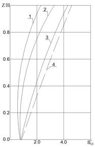
In the scientific articles of the above mentioned scientists, it is specifically mentioned that the calculation of different seismic vibrations within the railway track is mainly done based on the theoretical and experimental investigations. Fig. 1 depicts the allocation of seismic accelerations in the embankment soil with regard to the value of the seismic coefficient which considers the horizontal movements of the earthworks.
Fig. 1Seismic acceleration diagram of the embankment
4. Results and discussion
The slopes can be computed in two ways: when the soil can move over flat surfaces in case of the occurrence of layered sliding and when the soil can move over a cylindrical surface, which is circular.
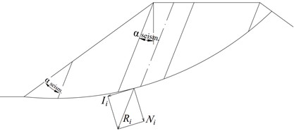
In relation to the method of calculating a circular cylindrical sliding surface, G. M. Shakhunyans suggested a method of determining the slope, taking into consideration seismicity. [8]. The surface of the sliding area is divided into sections at an angle to the vertical by planes in Fig. 2.
Fig. 2Diagram to compute the slope using the G. M. Shakhunyans method
The angle of deviation of the railway track with vertical is determined in the high seismicity zones with the help of the following Eq. (3):
The equivariant - of every section (with weight ) is determined with the direction of seismic forces represented as horizontal:
where:
from where:
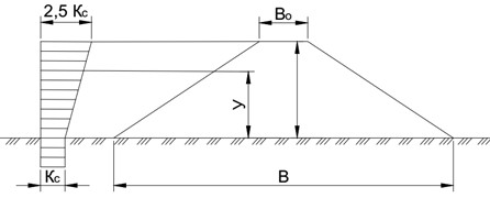
As an example, we will take the calculation scheme presented in Fig. 3, worked out by M. A. Revazov and T. K. Pustovoytov in order to calculate the stability of the structures located on any slope [8], [9]. The computation scheme takes into account the calculating methodology with the elements of the gravitational forces of the structure [10].
Checking of seismic stability that may lead to layered landslides is conducted in terms of the following formula:
where – angle of inclination to the seismically stable slope horizon at the considered level from the base of the embankment (Fig. 4); – dimensionless value of the intensity of the horizontal seismic inertial load, determined by the graphs in Fig. 5. (depending on the ratio of and ); – height of the embankment, m; – embankment’s natural oscillation period, sec.
Fig. 3Case of finding the slope by the method of M. A. Revazov and T. K. Pustovoytov
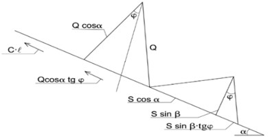
Fig. 4Embankment slope calculation scheme in case of layered landslides on seismic impact
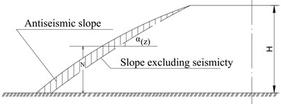
Fig. 5Table of calculating non-dimensional strength of the horizontal seismic load of inertial
Determination of values of is calculated using the formula (the simplified formula of Sh. G. Napetvaridze is taken into account):
where – upper embankment width, m; – embankment width below, m; – bulk density of soil, t/m3; – displacement modulus of the embankment material (displacement modulus), t/m2, approximately equal to 1000 t/m2, – height of the earthwork, m.
Checking of seismic stability on the possibilities of being displaced on a circular cylindrical surface is performed on the basis of accepted provisions: the minimum coefficient of stability is defined, but simultaneously, the active moment under seismic impact is also inserted into the computation., :
where and – passive and active moments relative to the center of rotation 0:
where – seismic force, applied to the center of gravity of the section and directed horizontally, when is equal to: 1-2.5 sec; 2-1 sec; 3-0.3 sec; 4 (obtained by extrapolation) – 0.1 sec, – distance from the boundary of a circular collapse to the center of a circle, (m).
In line design, it is advisable to come up with the slope steepness by the use of the formula:
where – width of the active soil zone, (m) for sandy soils: 2 h, for cohesive soils 3 h; – excavation depth, (m); – slope ratio of the railway subgrade embankment in non-seismic areas (); – relative compaction coefficient of the embankment soil (in fractions of the standard); – coefficient depending on the seismicity of the railway track section (SNiP II-7-81), 0.25; – coefficient that takes into account the permissible damage to railways (SNiP-II-7-81: for railways – 0.25); – the dynamic response coefficient of the subgrade soil (based on experimental results, the values are as follows: clay – 12, loam – 20, sandy loam – 30, gravel and crushed stone – 40, coarse sand – 50, medium sand – 60, fine (barchan) sand – 70).
The value of the slope required to increase the seismic resistance of the embankment built from clay soils is determined by the Eq. (12):
The value of the slope required to increase the seismic resistance of an embankment constructed from fine barchan sands is determined by Eq. (13):
Using the expression proposed above, it was established and scientifically substantiated that the slope value determined in clay soils is 24 % higher than in fine barchan sands.
The above Eqs. (1), (2), (3), (7) were proposed by various scientists for calculating anti-seismic slopes to ensure the seismic resistance of the railway track. The slopes determined using these expressions are characterized by the complexity of manufacturing and the parabolic shape of the slope. The Eq. (11) we developed experimentally is based on the simplicity of the slope preparation process and the calculation of the optimal antiseismic slope.
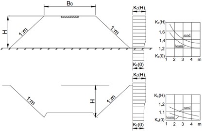
Slopes on the excavations, provided that they are on the same soil and topography conditions as the embankment slopes, are more seismically stable than the respective embankment slope. As demonstrated by special studies and experiment of seismic platforms, the distribution of seismic accelerations along the height of the excavation slopes contrary to the slopes of the embankments, is practically constant in Fig. 6.
Currently, various modern structures, including geomaterials, reinforced concrete piles, and chemical liquids, are being used to enhance the stability of earthworks located in seismically active areas. Considering that the technical and economic indicators of these structures are at a high level, an expression for calculating the optimal variant of earthquake-resistant slopes has been experimentally determined. The novelty of the research lies in the fact that creating this anti-seismic slope is economically inexpensive when preparing it in a simple technological process by compacting the natural soil shown in Fig. 4. In addition, when erecting earthquake-resistant earthworks, the main goal is to consider the structure's own weight. The structure we recommend has a smaller own weight compared to other structures, which leads to a reduction in seismic load.
Fig. 6Apportionment of seismic accelerations across the slope of embankment and excavation: KcO – seismicity coefficient of the level of the slope base; KcH – coefficient of seismicity in the upper edge of the slope
5. Conclusions
1) Using Eq. (11) developed experimentally, the optimal variant of railway track slopes was determined. It was shown that with an increase in the slope of the embankment from 2 to 4, the value of the seismic coefficient decreases by 12.5 %.
2) The dependence of soil types on the design and construction of slopes for ensuring the stability of railways located in seismically active areas has been experimentally determined. Based on the conducted experiments, it was established that the dynamicity coefficient of the earthen floor in clay soils is 83 % higher than in barchan sands.
References
-
P. Yi, J. Song, Q. Chen, and Y. Liu, “Seismic isolation design and resilience improvement of railway station considering the influence of near-fault pulse-like ground motions,” Earthquake Engineering and Engineering Vibration, Vol. 24, No. 1, pp. 257–270, Dec. 2024, https://doi.org/10.1007/s11803-025-2289-5
-
D. Connolly, A. Giannopoulos, and M. C. Forde, “Numerical modelling of ground borne vibrations from high speed rail lines on embankments,” Soil Dynamics and Earthquake Engineering, Vol. 46, pp. 13–19, Mar. 2013, https://doi.org/10.1016/j.soildyn.2012.12.003
-
R. Fang, Z. Lu, H. Yao, X. Luo, and M. Yang, “Study on dynamic responses of unsaturated railway subgrade subjected to moving train load,” Soil Dynamics and Earthquake Engineering, Vol. 115, pp. 319–323, Dec. 2018, https://doi.org/10.1016/j.soildyn.2018.08.037
-
A. Abdujabarov and M. Mekhmonov, “Structures options for the coastal bridge support, taking into account the seismicity of the district,” in AIP Conference Proceedings, Vol. 2471, p. 030045, Jan. 2022, https://doi.org/10.1063/5.0093489
-
A. Abdujabarov, M. Mekhmonov, P. Begmatov, F. Eshonov, and M. Khamidov, “Consideration of the environmental impact on the seismic inertial forces of the railway track in difficult conditions,” in AIP Conference Proceedings, Vol. 3045, p. 030097, Jan. 2024, https://doi.org/10.1063/5.0197332
-
M. Mekhmonov, S. Makhamadjonov, and A. Uralov, “Stabilization of embankments and coastal bridges with reinforced concrete piles,” in E3S Web of Conferences, Vol. 508, No. 9, p. 08018, Apr. 2024, https://doi.org/10.1051/e3sconf/202450808018
-
M. Mekhmonov and S. Makhamadjonov, “Investigation of the period of natural oscillations of the embankment on approaches to bridges,” in E3S Web of Conferences, Vol. 401, p. 05032, Jul. 2023, https://doi.org/10.1051/e3sconf/202340105032
-
K. S. Lesov, M. M. Rasulmukhamedov, A. K. Mavlanov, and M. K. Kenjaliyev, “Tension of ground pressure on the foundations of railway catenary supports,” in E3S Web of Conferences, Vol. 401, p. 03035, Jul. 2023, https://doi.org/10.1051/e3sconf/202340103035
-
G.-A. Khalfin, K. Umarov, I. Purtseladze, and M. Yembergenov, “System for determining state of continuous welded track,” in E3S Web of Conferences, Vol. 401, p. 02050, 2023, https://doi.org/10.1051/e3sconf/202340102050
-
A. Abdujabarov, F. Eshonov, P. Begmatov, M. Mekhmonov, and M. Khamidov, “Calculation of the seismic stress state of the ground-gallery system,” in AIP Conference Proceedings, Vol. 3045, p. 030098, Jan. 2024, https://doi.org/10.1063/5.0197333
About this article

The authors have not disclosed any funding.
The datasets generated during and/or analyzed during the current study are available from the corresponding author on reasonable request.
The authors declare that they have no conflict of interest.
