Abstract
Railway shunters ride on wagon footsteps and hold steel handrails amid coupling impacts, jerks and track-induced vibration. This study develops a two-degree-of-freedom model of a detachable cover clamped to a standard handrail without drilling or welding. Retaining cover-shell inertia gives coupled equations and closed-form transfer functions for the shell and an effective hand mass. Four 60-80 Shore A variants are evaluated under three idealized spectra. With adopted parameters, the hand-dominated mode is 22.6-25.1 Hz, compared with 25.2 Hz for the bare handrail, whereas the shell mode is 158-814 Hz. Two comparisons are required. The model-based biodynamic response ratio compares with the bare-hand response and remains 1.00-1.07. The contact-surface ratio compares with bare-rail motion and, over the common 8-200 Hz validity band, is 1.00-1.06 after weighting and 1.00-1.48 without weighting. Thus, internal hand response, shell motion and an ISO 10819 palm-adapter output must not be treated as the same observable. A necessary stiffness condition, , is combined with the anti-rotation pressure constraint. For the assumed 2-3 MPa admissible pressure, the four variants would require approximately 12-78 MPa to reach that stiffness condition; this is a parameter-dependent feasibility result, not a universal impossibility proof. A minimax screen favours V4 within this band, but no full-band optimum is claimed. Engineering benefits remain anti-rotation retention, ergonomics and retrofit installation. A verification programme using paired rail/cover measurements, a separate standard glove test and a slip-torque test is proposed.
1. Introduction
Railway shunters take part in train formation and other manoeuvring operations. They ride on a wagon footstep while holding the standard handrail of a moving freight or passenger wagon. Coupling, uncoupling, run-in impacts, starting jerks and passage over rail joints generate shocks and broadband structure-borne vibration [1, 2]. Longitudinal coupler forces can reach hundreds of kilonewtons. Measurements of freight-car environments also show switching shocks of several g, even with cushioned draft gear [3, 4]. These loads reach the handrail and then the worker's hand and forearm. The authors previously analysed the mechanical loading of shunters during these operations [5].
Repeated hand-arm vibration and shock are associated with hand-arm vibration syndrome. Its effects include vascular, neurological and musculoskeletal disorders [6, 7]. Vehicle studies confirm the relevance of vibration and acoustic loading in transport work [8]. ISO 5349-1 defines the accepted exposure evaluation method [9]. Acceleration is frequency-weighted with , combined over three axes into and normalized to the 8-hour energy-equivalent exposure A(8). Directive 2002/44/EC sets an action value of 2.5 m/s2 and a limit value of 5 m/s2 [10]. For example, = 8 m/s2 acting for 2 h gives A(8) = 4 m/s2, above the action value.
A freight-wagon handrail is normally a smooth round steel bar [11]. It provides structural strength but offers limited ergonomic support. Its friction falls when the surface is wet, icy or oily. Steel also feels cold in winter and transmits structure-borne motion directly to the contact surface. These effects are important because the handrail grip is the worker's principal fall-prevention support while riding on the footstep.
Elastomeric and anti-slip covers are used on sports equipment, bicycle handlebars, tools and domestic handrails. Known examples include ergonomic shock-absorbing grips [12], damping covers for implement handles [13] and tuned mass dampers for handlebars [14]. They are not designed for railway weather, contamination or torsional loading on a round steel rail. Railway elastomers can suppress other vibrodynamic effects, as shown by under-sleeper pads at rail joints [15]. A perforated wagon handrail has also been patented [16], but it requires replacement of the standard rail. The closest prototype is a two-half-shell haptic cover [17]. Its retention is directed mainly against longitudinal slip and does not provide dedicated anti-rotation relief or a separately characterized damping layer.
Shunters work in protective gloves, and anti-vibration gloves are evaluated under ISO 10819 [18]. Experimental studies and multi-degree-of-freedom glove models show that compliant interfaces mainly affect components above about 100-150 Hz [19, 20]. -weighted exposure is dominated by lower frequencies, so the weighted benefit is usually small and may reverse near an interface resonance. A new cover must therefore be assessed with frequency weighting, a clearly defined reference state and a clear distinction between the measured surface motion and an internal biodynamic coordinate.
This work develops a reduced-order vibration model and uses it to evaluate a detachable cover for a standard wagon handrail. The design must resist angular slip, provide a weather-resistant ergonomic grip and remain installable without drilling or welding. It is the subject of an Uzbekistan patent application [21]. The contributions are application-specific rather than a claim that two-degree-of-freedom glove models are new in general. First, shell inertia is retained in a closed-form railway handrail-cover-glove-hand model, and the vanishing-mass limit is recovered. Second, output-specific references separate contact-surface motion from modelled hand response. Third, the necessary stiffness condition is combined with anti-rotation retention and pressure sensitivity. Fourth, a minimax criterion covers both outputs and three excitation spectra. Fifth, a measurement map identifies the observable obtained by each proposed test. Sixth, these tools are integrated with a retrofit anti-rotation cover for railway shunters. Section 2 describes the device. Section 3 develops the models and metrics. Section 4 presents the parametric results and verification plan. Section 5 gives the conclusions.
2. Design of the detachable handrail cover
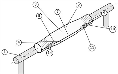
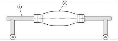
The detachable vibration-damping ergonomic cover is intended for installation on the working part of the standard round wagon handrail. The design (Fig. 1) comprises a split rigid body, an inner viscoelastic elastomer layer with a friction contact surface, and an outer working surface with anatomical zoning [21].
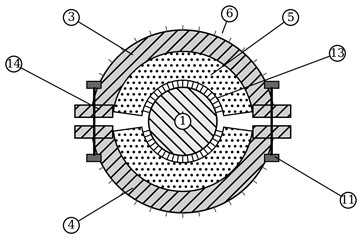
The body of the cover is formed by two half-shells 3 and 4, made of an impact-resistant structural polymer such as polyamide PA-6, which embrace the handrail 1 and are joined by side flanges 14 tightened by fixators 11. Screw, bolt, clamp-band, latch or combined fixators can be used. This solution allows the cover 2 to be mounted without drilling or welding of the standard rail: the half-shells are placed around the working part of the handrail and the fixators are tightened. A worn cover is replaced in the same way, so the device is a serviceable, replaceable wear part.
A viscoelastic polyurethane or thermoplastic-elastomer layer 5 lies between the rigid body and the steel handrail. Candidate hardness is 60-80 Shore A over the intended outdoor temperature range. The layer supplies damped compliance and frictional retention; a reduction in exposure is not assumed a priori. Its inner face carries ribs, knurling or notches forming the friction relief 13. Tightening the fixators creates radial preload, concentrates pressure at the rib crests and promotes micro-interlock with rail roughness. The resisting torque must exceed the traction-torsion moment applied during acceleration, braking and impacts; Section 3.4 quantifies this condition. Reducing the relief area ratio lowers layer stiffness but raises crest pressure. The vibration and retention functions are therefore coupled by a constraint, not assumed to be synergistic.
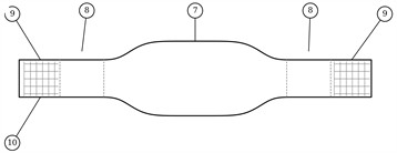
The outer working surface 6 has an anatomically zoned profile. The central zone 7 of enlarged diameter is intended for the full palm grip; the transition zones 8 with a smooth taper serve for re-gripping; the end zones 9 are intended for finger retention and carry an anti-slip texture 10 in the form of longitudinal, transverse, diagonal or combined ribs and grooves. Because the cover cannot rotate about the rail, the angular orientation of these zones with respect to the worker remains fixed in service. In the lower part of the body, drainage-ventilation channels 12 connect the contact zone between the cover and the rail with the environment and evacuate moisture, condensate and contaminants, which stabilizes the friction conditions during operation in precipitation and dust. For heavy-duty applications a coaxial reinforcing insert can be moulded into the central zone of the half-shells.
Fig. 1Design of the cover: a) isometric general view of the cover 2 installed on the working part of a standard wagon handrail 1; b) front view; c) cross-section: 3, 4 – half-shells; 5 – damping layer; 6 – outer surface; 11 – fixators; 13 – friction relief; 14 – side flanges; d) longitudinal zoning of the outer surface: 7 – central palm zone; 8 – transition zones; 9 – end finger-grip zones; 10 – anti-slip texture
a)
c)
b)
d)
3. Vibration transmission model and evaluation methodology
This section develops the analytical basis of the study. Subsection 3.1 recalls the metrics by which hand-transmitted vibration is assessed and explains why weighted and unweighted quantities have to be reported side by side. Subsection 3.2 formulates the two-degree-of-freedom model of the transmission tract, derives the two transfer functions in closed form, recovers the single-degree-of-freedom description as a limiting case and states the frequency range in which the lumped description remains admissible. Subsection 3.3 establishes the effective mass of the cover from a mass budget of its parts. Subsection 3.4 describes the friction retention model of the anti-rotation function. Subsection 3.5 defines the excitation spectra, fixes the reference configuration against which the device is judged and introduces the evaluation ratios and the insertion loss.
3.1. Hand-transmitted vibration metrics
According to ISO 5349-1 [9], the root-mean-square acceleration measured at the grip is frequency-weighted in third-octave bands from 6.3 to 1250 Hz with the weighting , which is close to unity in the 8-16 Hz bands (0.87-0.96) and decreases approximately inversely with frequency above 16 Hz. The weighted accelerations of the three basicentric axes are combined into the vibration total value:
and the daily exposure is normalized to 8 h:
where is the daily exposure duration and = 8 h. strongly de-emphasizes the range above 100 Hz, where resilient interfaces often have their largest dynamic effect. The supplementary weighting of ISO/TR 18570 [22] gives more weight to higher frequencies. Weighted and unweighted quantities are therefore reported side by side. The standard contact-surface metric is formed from , while / is reported separately as a reduced-order biodynamic response index. The numerical study represents the dominant radial axis. The same equations may be applied independently to other axes only after axis-specific inputs and parameters are identified; the scalar results alone do not determine the three-axis values or A(8).
3.2. Two-degree-of-freedom transmission model
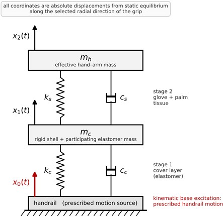
The transmission tract from the handrail to the hand is represented by the lumped model in Fig. 2. Models of this class are routinely applied to transport-machinery units containing compliant elastomer elements, such as rotor systems on polyurethane support layers [23]. Comparable reduced-order vibration models are also used for freight-vehicle suspensions under vibration-induced fatigue [24]. The handrail is an ideal prescribed-motion source because its mechanical impedance is much higher than that of the hand. The first moving body is the rigid shell plus the dynamically participating elastomer mass , with absolute displacement . The second is the effective hand-forearm mass , with displacement . The cover layer forms stage 1 (, ), and the glove plus palm tissue forms stage 2 (, ). The reference mass ratio / is about 0.14, rather than negligible, and produces the shell mode examined in Section 4.
The coordinates in Fig. 2 are measured from static equilibrium along one selected basicentric direction. The numerical results below use the dominant radial direction of the grip. Applying Newton’s second law to each moving body gives the two coupled equations:
Fig. 2Two-degree-of-freedom model of the handrail-cover-glove-hand tract. Each coordinate arrow starts directly on its body. x0t is the prescribed handrail displacement and the sole kinematic excitation; x1t and x2t are the absolute displacements of the shell and effective hand mass along the selected radial axis
In matrix form, with , the system reads , where the excitation vector collects the terms transferred from the moving base. For harmonic excitation the response is with the dynamic stiffness matrix . For an elastomer the viscous element is replaced by the hysteretic (complex-stiffness) description, which reproduces the frequency-independent loss factor of rubber-like materials [25, 26]:
where and are the loss factors of the cover layer and of the glove–tissue stage. The equivalent viscous damping ratio of an isolated stage is . Solving the two-by-two system by Cramer’s rule gives the two transfer functions in closed form. The transmissibility to the hand and the transmissibility to the shell are, respectively:
where the common denominator is:
The two outputs have different physical meanings. is the modelled motion of the effective hand mass and is used below as a reduced-order biodynamic response. is the motion of the rigid cover shell and can be measured relative to the rail by accelerometers bonded to those bodies. A palm adapter inside a glove under ISO 10819 includes the glove transmission and is not automatically equal to either coordinate in this lumped model. Section 4.4 maps the outputs to the proposed measurements. The undamped natural frequencies follow from 0:
Whose two roots give the tract mode , dominated by the hand on the compliant glove-tissue stage, and the shell mode , dominated by the cover mass on the elastomer layer. Setting 0 in Eq. (8) collapses the denominator and recovers the single-degree-of-freedom result used in earlier treatments of this problem:
The two-degree-of-freedom model therefore contains the earlier description as a special case, and the difference between them is controlled by the mass ratio . The lumped description itself remains admissible only while the elastomer layer is acoustically thin, that is, while the excitation frequency stays well below the first internal wave resonance of the layer:
where is the first internal shear-wave resonance and = /4 is adopted as a conservative screening limit for the lumped layer. For V1-V4, is approximately 202, 253, 417 and 814 Hz. Each predicted shell mode lies below its own limit, but only 8-200 Hz is common to all four variants. Band-synthesized comparisons therefore use 8-200 Hz. Curves and tabulated points above a variant’s are shown only as trend extrapolations and require a distributed-parameter or finite-element model for confirmation.
The compression stiffness of the cover layer over the loaded contact arc is estimated as:
where is the full area of the loaded contact arc (for a palm grip of about 90 mm length on a rail of 30 mm diameter, 30 cm2), 1 is the relief area ratio, that is the fraction of actually carried by the rib crests of the friction relief, is the layer thickness and is the Young’s modulus of the elastomer. Because the relief subdivides the layer into low, narrow ribs, the shape factor of the loaded elements remains small and the apparent modulus stays close to [25, 26]. The modulus is estimated from the Shore A hardness by the Gent relation [27]:
which gives = 3.61, 5.52 and 9.35 MPa for 60, 70 and 80 Shore A respectively. The effective mass of the hand coupled at a cylindrical grip is taken as = 2.0 kg. This value is consistent both with the standard body-segment parameters of Winter [28], according to which the forearm-and-hand segment amounts to 0.022 of body mass, about 1.5-1.7 kg for a 70-75 kg worker, and with the apparent mass of the hand–arm system at the palm in the 20-80 Hz region given by the biodynamic data of ISO 10068 [29], namely 1.5-2.5 kg. The adopted value also accounts for the part of the forearm dynamically coupled at the grip. For the glove-and-tissue stage 5×10⁴ N/m is adopted as an order-of-magnitude estimate [19]; with = 2.0 kg this places the driving-point resonance of the bare hand-rail contact at 25.2 Hz, in agreement with the hand-arm resonance region reported for the palm. Because this single parameter governs the whole conclusion of the study, its influence is examined explicitly in Section 4.6. For damping, high-damping polyurethanes and thermoplastic elastomers have loss factors 0.3-0.6; the hand tissue is more heavily damped and = 0.6 is adopted. High-loss elastomers and polymer composites for vibration-damping elements of transport vehicles are an area of active development [30, 31], so the upper part of this range is practically attainable.
3.3. Effective mass of the cover
The effective mass of the first body is obtained from a mass budget of the parts that move with the shell. For a cover of 200 mm working length installed on a rail of 15 mm radius, with an elastomer layer of 8 mm and half-shells of 4 mm wall thickness, the polyurethane layer ( = 1150 kg/m3) weighs 0.220 kg, the polyamide half-shells ( = 1140 kg/m3) 0.143 kg, and the flanges with the fixators about 0.050 kg. Following the Rayleigh procedure for a distributed spring, one third of the layer mass is added to the moving body:
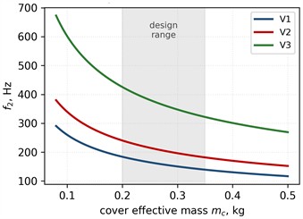
A mass ratio of one seventh is not negligible, and Section 4 shows that it determines the position of the second resonance of the tract. The sensitivity of the results to over the range 0.10-0.45 kg is reported in Fig. 3(c) and Section 4.6.
3.4. Anti-rotation retention model
The anti-rotation function of the friction relief is described by a torque balance. When the fixators are tightened to a total radial clamping force distributed over the contact arc, the cover is retained on the rail by the friction torque:
where is the effective friction coefficient of the relieved elastomer-steel pair and is the handrail radius; for a relief forming several distinct contact zones, the products of the zone forces and friction coefficients are summed. Reliable retention requires:
= 10 N·m, = 0.6, = 15 mm and = 1.5 are used as screening values. They give 1.67 kN. Two M6 flange fixators tightened to 3-5 N·m may generate a total preload of roughly 5-8 kN, but the torque-preload relation has wide scatter and must be measured for the actual joint. At = 1.67 kN and = 0.20, the nominal crest pressure /() is about 2.8 MPa. Because long-term admissible pressure has not yet been established for the selected elastomer, temperature and contamination, = 2-3 MPa is treated only as a sensitivity range in Section 4.5. Reducing lowers stiffness but raises crest pressure, so the two functions are coupled by Eqs. (12), (15) and (16).
3.5. Excitation spectra, reference configuration and evaluation ratios
Three idealized third-octave rail-input spectra are defined over 8-1000 Hz for measurement planning. is flat. is constant to 16 Hz and then proportional to 16/, representing ride- and jerk-dominated motion. S3 is proportional to (/16)1/2 and capped above 250 Hz, representing impacts and structural ringing. The lumped-model band synthesis uses only the common conservative range 8-200 Hz established by Eq. (11). Full-band workplace exposure must be obtained experimentally. The alternative to the device is a bare handrail gripped through the same glove and palm tissue, represented by:
The bare configuration has a resonance at 25.2 Hz for the adopted parameters. Two output-specific references are required. The modelled hand response with the cover, , is compared with the bare-hand response . The cover-surface motion, , is compared with the bare rail surface, whose transmissibility relative to the prescribed rail input is unity. Using as the denominator of a ratio would compare different physical outputs and create a spurious result. The two band-synthesized ratios are therefore:
where is the rail-input band acceleration. gives the weighted ratios and 1 the unweighted ratios. is the contact-surface quantity relevant to a same-duration, one-axis ISO 5349 comparison. is an internal model-response index and is not itself or A(8). For three-axis exposure, the measured axis-specific accelerations must first be combined as in Eq. (1). Frequency-specific changes are reported as:
4. Results and discussion
This section applies the model to four cover variants. Section 4.1 establishes their stiffness and modal frequencies. Section 4.2 reports the modelled hand response and its insertion loss against the bare-hand configuration. Section 4.3 evaluates both the biodynamic and contact-surface ratios with their correct references. Section 4.4 relates and to feasible measurements. Section 4.5 combines the necessary stiffness condition with retention and pressure constraints. Section 4.6 gives sensitivities and the combined design criterion. Sections 4.7 and 4.8 discuss the technical effect, limitations and verification programme.
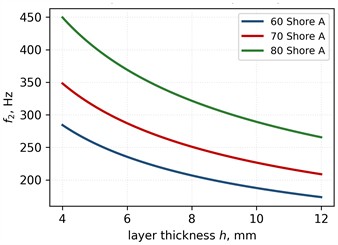
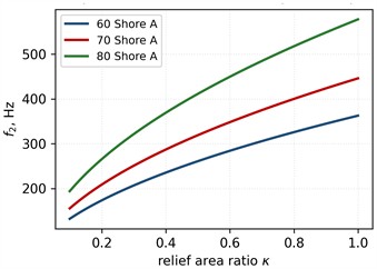
Fig. 3Design charts of the shell mode f2: a) effect of the layer thickness for three hardness grades (κ = 0.3); b) effect of the relief area ratio (h = 8 mm); c) effect of the effective cover mass for variants V1-V3
a)
b)
c)
4.1. System modes and the stiffness of the cover layer
Table 1 presents four design variants of the cover layer spanning the claimed material and geometry range, from a soft, thick layer with a deep relief (V1) to a hard, thin layer with full contact (V4). The layer stiffness varies by a factor of 32, from 216 to 7014 kN/m. The decisive quantity, however, is not itself but its ratio to the stiffness of the glove-tissue stage: / ranges from 4.3 to 140. Because the two stages act in series, the compliance of the tract is set by the softer of them, and the series stiffness therefore stays within 81-99 % of for every variant. The first natural frequency consequently moves only from 25.2 Hz for the bare handrail to 22.6-25.1 Hz with the cover fitted. This explains, and corrects, the illustrative value 20 Hz adopted in the patent application [21]: it characterizes the hand on its own tissue rather than any property of the cover. The second natural frequency is new. It is the shell mode, in which the mass oscillates on the elastomer layer, and it falls between 158 and 814 Hz. For the softer variants it lies inside the frequency range that carries the impact content of the excitation. A single-degree-of-freedom model cannot reproduce this mode at all, which is the principal reason for retaining .
Fig. 3 maps the main levers acting on . Increasing , reducing hardness or , and increasing lower the shell-mode frequency. Reducing mass raises without increasing crest pressure. Each V1-V4 shell mode remains below its own conservative , although V4 lies close to that boundary. Section 4.5 therefore treats stiffness and retention as a conditional feasibility problem, while Section 4.6 avoids a full-band ranking until the high-frequency model and material data are validated.
Table 1Design variants of the cover layer (A0 = 30 cm2, mh = 2.0 kg, ks = 5·104 N/m, mc = 0.27 kg)
Variant | Shore A | , mm | , kN/ | / | , Hz | , Hz | |
No cover | – | – | – | – | – | 25.2 | – |
V1 | 60 | 10 | 0.20 | 216 | 4.3 | 22.6 | 158.4 |
V2 | 60 | 8 | 0.30 | 406 | 8.1 | 23.7 | 206.9 |
V3 | 70 | 6 | 0.50 | 1380 | 27.6 | 24.7 | 366.3 |
V4 | 80 | 4 | 1.00 | 7014 | 140.3 | 25.1 | 814.0 |
4.2. Transmissibility and insertion loss relative to the bare handrail
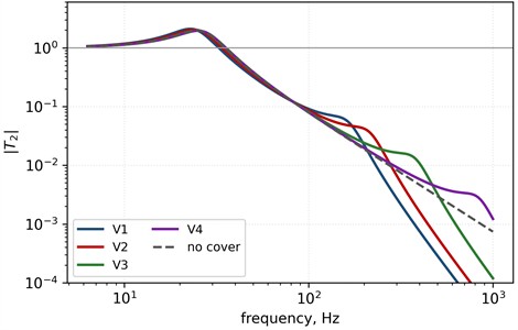
Table 2 and Fig. 4 compare the modelled hand response of V1 with the bare-hand response of Eq. (17). Below about 30 Hz both configurations amplify the input, and the cover lowers the tract resonance from 25.2 to 22.6 Hz. The biodynamic insertion loss is therefore –0.1 to –1.4 dB in this range. Between 30 and 100 Hz the curves are close and remains within ±2.2 dB. The 158 Hz shell mode raises above , giving –5.9 dB at 160 Hz. Values at 250 and 500 Hz illustrate the formal lumped-model roll-off, but exceed the conservative V1 limit 202 Hz and are not used in the integrated metrics. These figures describe the internal reduced-order response, not the ISO 5349 contact-surface acceleration.
Table 2Modelled hand response and biodynamic insertion loss of V1 relative to the bare-hand configuration (ηc = 0.4, ηs = 0.6). Values above 202 Hz are trend extrapolations
, Hz | , dB | |||
8 | 1.079 | 1.106 | 1.025 | −0.2 |
16 | 1.379 | 1.540 | 1.117 | −1.0 |
20 | 1.656 | 1.937 | 1.169 | −1.4 |
25 | 1.943 | 1.962 | 1.010 | −0.1 |
31.5 | 1.413 | 1.094 | 0.774 | 2.2 |
50 | 0.388 | 0.320 | 0.825 | 1.7 |
63 | 0.220 | 0.195 | 0.888 | 1.0 |
80 | 0.128 | 0.126 | 0.987 | 0.1 |
100 | 0.079 | 0.091 | 1.155 | −1.2 |
125 | 0.049 | 0.074 | 1.492 | −3.5 |
160 | 0.030 | 0.058 | 1.971 | −5.9 |
250 | 0.012 | 0.007 | 0.559 | 5.0 |
500 | 0.003 | 0.0003 | 0.097 | 20.3 |
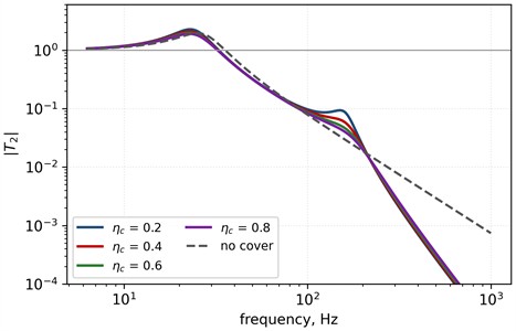
Table 3 extends the comparison to all four variants at octave-band centre frequencies. At 16, 31.5 and 63 Hz every variant remains close to the bare-hand response. At 125 and 250 Hz the softer variants are influenced by their shell modes, while V4 is close to the bare biodynamic reference. A systematic reduction in appears only at 500 Hz and is largest for V1. Higher damping flattens the modal peaks but slows the high-frequency roll-off (Fig. 4(b)). Entries above the variant-specific values in Section 3.2 are screening extrapolations.
Fig. 4Modelled transmissibility to the effective hand mass: a) V1-V4 and the bare configuration; b) loss-factor sensitivity for V1. Curve segments above each variant’s flim are trend extrapolations
a)
b)
Table 3Modelled biodynamic transmissibility T2(f) at octave-band centre frequencies (ηc = 0.4); see the variant-specific validity limits in Section 3.2; italicized entries lie above that variant’s flim and are screening extrapolations
Configuration | 16 Hz | 31.5 Hz | 63 Hz | 125 Hz | 250 Hz | 500 Hz |
No cover | 1.379 | 1.413 | 0.220 | 0.049 | 0.012 | 0.0030 |
V1 | 1.540 | 1.094 | 0.195 | 0.074 | 0.007 | 0.0003 |
V2 | 1.462 | 1.238 | 0.207 | 0.062 | 0.018 | 0.0006 |
V3 | 1.403 | 1.362 | 0.216 | 0.053 | 0.019 | 0.0032 |
V4 | 1.384 | 1.403 | 0.219 | 0.050 | 0.013 | 0.0043 |
4.3. Frequency-weighted evaluation
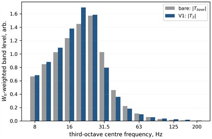
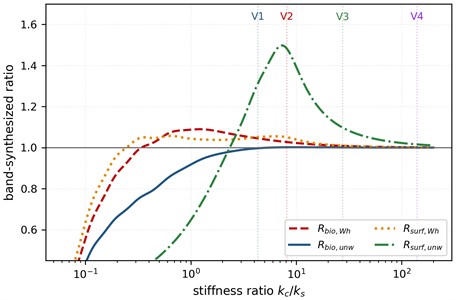
Table 4 separates the two comparisons defined by Eq. (18) over the common 8-200 Hz validity range. For the modelled biodynamic response, is 1.00-1.07 and is 1.00-1.06 across the four variants and three spectra. The contact-surface result is different. is 1.00-1.06, while ranges from 1.00 to 1.48 because the shell modes alter unweighted motion within the common band. These ranges apply only to the four discrete variants, adopted hand parameters and three idealized radial spectra. Fig. 5 shows the modelled S3 band levels and how both metric families vary with /. The curves demonstrate why a design optimized only for can amplify .
The small change in is consistent with anti-vibration-glove studies [19, 20], but it must not be presented as a direct prediction of or A(8). The standard quantity is based on measured contact-surface acceleration, represented here by only for the studied radial axis. Three consequences follow. First, the model alone does not justify a general exposure-reduction claim; field measurements over all three axes are required. Second, high loss remains desirable because it limits the shell resonance. Third, -weighted, unweighted, peak and -weighted results should be reported together so that a small weighted change does not hide high-frequency amplification.
Table 4Band-synthesized biodynamic (Rbio) and contact-surface (Rsurf) ratios over the common 8-200 Hz validity range for spectra S1-S3 (ηc = 0.4)
Configuration | Weighted (S1) | Unweighted (S1) | Weighted (S2) | Unweighted (S2) | Weighted (S3) | Unweighted (S3) |
Biodynamic ratios : compared with | ||||||
V1 | 1.06 | 1.03 | 1.07 | 1.06 | 1.05 | 1.00 |
V2 | 1.03 | 1.02 | 1.04 | 1.04 | 1.03 | 1.00 |
V3 | 1.01 | 1.01 | 1.01 | 1.01 | 1.01 | 1.00 |
V4 | 1.00 | 1.00 | 1.00 | 1.00 | 1.00 | 1.00 |
Contact-surface ratios : compared with the bare rail surface (= 1) | ||||||
V1 | 1.05 | 1.14 | 1.06 | 1.05 | 1.05 | 1.31 |
V2 | 1.03 | 1.19 | 1.03 | 1.03 | 1.05 | 1.48 |
V3 | 1.01 | 1.03 | 1.01 | 1.01 | 1.01 | 1.10 |
V4 | 1.00 | 1.01 | 1.00 | 1.00 | 1.00 | 1.02 |
Fig. 5Common-validity evaluation (8-200 Hz): a) Wh-weighted modelled hand-response band levels for S3, comparing T2 of V1 with Tbase; b) correctly referenced biodynamic and contact-surface S3 ratios versus kc/ks. Vertical lines mark V1-V4
a)
b)
4.4. Model outputs and measurement correspondence
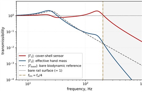
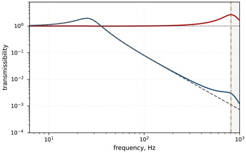
Fig. 6 makes the output distinction explicit. A sensor bonded to the cover shell and referenced to a sensor on the rail measures . The corresponding bare-surface reference is unity. The modelled hand coordinate must instead be compared with . For V1, corresponds to about 26 dB at 125 Hz and 31 dB at 160 Hz. The formal 38 dB result at 250 Hz lies beyond the conservative V1 limit and is shown only as an extrapolated trend. This divergence is caused by inertial decoupling; it is not an ISO 10819 palm-adapter result. In ISO 5349 workplace measurements, the transducer estimates acceleration at the hand-contact surface and is used to calculate and A(8). In ISO 10819 glove testing, the palm adapter lies inside the glove and measures the vibration transmitted through the glove relative to the test handle. The present model combines the glove and palm tissue in stage 2, so its two coordinates cannot reproduce that adapter signal. An additional interface coordinate and separately identified glove and tissue parameters would be required.
Fig. 6Output-specific transmissibilities: cover-shell motion T1 is compared with the bare rail surface (= 1), whereas modelled effective-hand motion T2 is compared with the bare biodynamic reference Tbase: a) V1; b) V4. Shading begins at the conservative variant-specific limit flim
a)
b)
4.5. Necessary stiffness condition and retention constraint
The model gives a useful order-of-magnitude screening condition. Because the cover layer and glove–tissue stage act in series, the cover cannot materially reduce the combined quasistatic stiffness unless its stiffness is comparable with or smaller than . Thus the following is a necessary, but not sufficient, condition for appreciable resonance shift:
Anti-rotation retention acts in the opposite direction. Eqs. (15) and (16) require . With = 1.5, = 10 ·, = 0.6 and = 15 mm, the illustrative minimum is 1.67 kN. If the rib crests carry this force over , the admissible long-term contact pressure gives the lower bound:
Substituting Eq. (21) into Eq. (20) eliminates and yields an explicit upper bound on the modulus of the elastomer, and hence, through the Gent relation Eq. (13), on its Shore hardness:
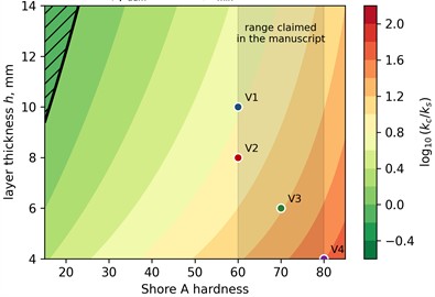
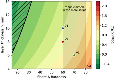
For = 3 MPa and = 12 mm, Eq. (22) gives 1.08 MPa, or about 29 Shore A by Eq. (13). For 2 MPa and 10 mm it gives 0.60 MPa, or about 16 Shore A. These values are sensitivity examples because , and have not yet been measured for the proposed material, temperature and contamination states. An equivalent way to expose that dependence is to solve Eq. (22) for pressure. V1-V4 would require about 12, 15, 31 and 78 MPa, respectively, before Eq. (20) could be met; each exceeds the assumed 2-3 MPa range. Accordingly, the necessary stiffness and retention conditions do not overlap under the adopted assumptions, but the analysis is not a universal impossibility proof. At = the S3 biodynamic calculation gives 0.92 and 1.09, which also shows that satisfying the necessary condition would not by itself guarantee a favourable standard exposure result.
Fig. 7Illustrative feasibility map for the adopted retention parameters. Contours show log₁₀(kc/ks) after κ is set by Eq. (21): a) padm = 2 MPa; b) padm = 3 MPa. Hatching marks the necessary condition kc≤ks. The map is a pressure-sensitivity calculation, not a universal material limit
a)
b)
4.6. Parametric sensitivity and design recommendations
The influence of the design parameters on the two natural frequencies is quantified by logarithmic sensitivities:
For , the shell mode is approximately . Eqs. (9), (12) and (13) then give +0.5 and = −0.5. The Shore-hardness sensitivity is about 1.2, 1.6 and 2.5 at 60, 70 and 80 Shore A. Thus one Shore unit changes by roughly 2-3 %. Across the considered ranges, , , hardness and shift by factors of approximately 2.2, 1.6, 1.6 and 2.1. Mass is the only one of these levers that does not directly tighten the contact-pressure constraint. For the tract mode, sensitivity to is small when / is large, while sensitivity to approaches 0.5. Raising from 0.2 to 0.8 reduces the V1 peak and improves its S3 biodynamic ratios, but the corresponding metrics must be checked separately. Varying from 25 to 400 kN/m changes the predicted benefit substantially, confirming that must be identified experimentally rather than treated as a universal hand parameter.
A defensible design objective must control both physical outputs. Let = (, , , , ) belong to the feasible set defined by retention, pressure and geometry constraints. For the three spectra used here, the combined vibration-neutrality problem is:
where is the outer grip diameter, its ergonomic and clearance limit, and the prescribed lower shell-mode bound. The constraint () 200 Hz keeps every candidate within the common admissible band. Eq. (24) is a discrete minimax screen, not a claimed continuous optimization. On the four-variant 8-200 Hz grid, V4 has the smallest maximum rounded departure (about 2 %) across the twelve ratios in Table 4. This is not a full-band optimum: its shell mode is near 814 Hz, and rankings change when extrapolated bands are included. Final material selection therefore requires measured spectra and a distributed high-frequency model. Table 5 summarizes the provisional guidance.
Table 5Provisional design recommendations from the combined two-output criterion
Design parameter | Recommendation | Rationale |
Layer stiffness | Select jointly; no full-band optimum is established | V4 minimizes the 8-200 Hz screen, but its shell mode lies near 814 Hz |
Shore hardness | No final grade before full-band tests | Temperature-dependent modulus and durability remain unknown |
Layer thickness | Verify jointly with grip diameter and | Changes stiffness, internal-wave validity and shell-mode position |
Relief area ratio | Set from measured pressure and slip torque | Retention and crest pressure require experimental confirmation |
Effective cover mass | As low and reproducible as practicable | Raises without increasing the contact-pressure demand |
Loss factor | 0.4, subject to low-temperature testing | Limits shell-mode amplification; both output metrics must be checked |
Inner relief pattern | Crossed ribs or notches | Resists axial slip and angular rotation |
Drainage channels | In the lower part of the cover | Stabilizes contact under moisture and contamination |
4.7. Discussion of the expected technical effect
The analysis supports three distinct functions. First, the friction relief provides a calculable anti-rotation mechanism that is absent from the closest prototype [17]. Its predicted margin still depends on the torque–preload relation and on friction under temperature, moisture and contamination. Second, anatomical zoning, drainage, anti-slip texture and low thermal conductivity can improve grip usability without modifying the standard rail. Third, the vibration target is neutrality rather than assumed isolation. Within the common 8-200 Hz band, V4 keeps both output families closest to unity; this does not establish a full-band optimum because its shell mode lies near 814 Hz. A very stiff shell can appear neutral in while amplifying high-frequency , and a soft shell can place its mode near 158-207 Hz. The retrofit character remains an operational advantage: the two half-shells are installed without welding, drilling or replacement of the rail. Limitations are the linear lumped model, one-axis radial numerical study, idealized spectra, combined glove-tissue stage, estimated , , , and , and the absence of prototype data. These limitations define the verification tasks below.
4.8. Proposed experimental verification procedure
Workplace measurements should follow ISO 5349-2 [32]. A tri-axial transducer or validated adapter should measure acceleration at the hand-contact surface in the basicentric axes, with instrumentation conforming to ISO 8041-1 [33]. The same operators, wagons and speed ranges should be tested with and without the cover. At least three operators and at least twenty coupling-uncoupling cycles per condition are proposed for the pilot stage. The confirmatory sample size should then be set by an a priori power analysis using the observed between-operator and cycle-to-cycle variance. Report , , , , A(8), peaks and third-octave spectra, together with uncertainty. Compact MEMS sensors may be used only after appropriate calibration and uncertainty evaluation [34, 35]. Risk-oriented processing of the recorded vibration signals, of the kind developed for predictive machine diagnostics [36], can be adapted to classify individual coupling events by severity rather than to average them.
A laboratory test should excite a standard handrail section from 8 Hz to at least the shell mode. Comparison with the lumped model is restricted to each variant’s from Eq. (11); a distributed or finite-element model is required above it. One accelerometer is bonded to the rail and another to the rigid cover shell in the palm zone. Their ratio is:
where and are the complex cover-shell and rail acceleration spectra, respectively. Eq. (25) validates , and ; it does not directly validate . requires a calibrated inertial hand surrogate or an identified hand-arm impedance model. The predicted and are the primary modal quantities to confirm. A separate ISO 10819 test should be used when glove transmissibility is required. Its palm-adapter result must not be labelled or unless the model is extended with a glove-palm interface coordinate and independently identified parameters. Finally, a slip-torque test should record the onset of angular motion for smooth and relieved surfaces under dry, wet, cold and contaminated conditions. These tests provide the axis-specific data needed before any three-axis A(8) claim is made.
5. Conclusions
1) A detachable ergonomic cover has been designed for a standard wagon handrail. It combines a clamped two-half-shell body, friction relief against rotation, anatomical zoning, anti-slip texture and drainage, and can be installed without drilling or welding [21].
2) The mathematical contribution is an application-specific two-degree-of-freedom model with explicit cover-shell inertia, two coupled equations and closed-form transfer functions. Its vanishing-mass limit recovers the reduced one-mass form, and Eq. (11) bounds the lumped-model frequency range. The adopted 0.27 kg cover mass produces a shell mode at 158-814 Hz for V1-V4.
3) Two reference states are required. The biodynamic index compares with and gives 1.00-1.07 over the common 8-200 Hz band. The contact-surface metric compares with unity and gives 1.00-1.06 after weighting and 1.00-1.48 without weighting. These scalar, band-limited results do not determine or A(8).
4) The condition is a necessary order-of-magnitude requirement for appreciable stiffness change, not a sufficient isolation criterion. Combined with the assumed retention parameters, it requires about 12-78 MPa contact pressure for V1-V4, above the adopted 2-3 MPa range. The non-overlap is therefore conditional on parameters that must be measured.
5) is measurable with sensors bonded to the shell and rail. is an internal model coordinate. An ISO 10819 palm-adapter output includes glove transmission and cannot be identified with either quantity in the present two-coordinate model. At 125 and 160 Hz, and differ by about 26 and 31 dB for V1; the formal 250 Hz value is outside the conservative V1 limit.
6) The retention equations predict that two M6 fixators can provide a margin above the illustrative 10 N·m service moment, but this depends on torque-preload scatter, friction, temperature and contamination. The slip-torque test is therefore a required validation, not a formality.
7) The combined minimax criterion favours V4 within the common 8-200 Hz range, with a maximum rounded deviation of about 2 %. Because its shell mode lies near 814 Hz and rankings are band-limit-sensitive, no full-band material optimum is claimed.
8) Verification requires paired rail/cover measurements, full three-axis workplace assessment, modal identification, a separate ISO 10819 glove test and slip-torque tests. Future work should identify material properties and hand parameters, manufacture prototypes, quantify uncertainty and test durability, cold conditions and field performance with serving shunters.
References
-
“Freight wagons of the main-line railways of 1520 mm gauge-general requirements for ensuring safety in loading-unloading and shunting operations,” Standartinform, Moscow, Russia, 2011.
-
C. Cole, “Longitudinal train dynamics,” in Handbook of railway vehicle dynamics, Boca Raton, FL, USA: CRC Press, 2006, pp. 239–277, https://doi.org/10.1201/9781420004892.ch9
-
Q. Wu, M. Spiryagin, and C. Cole, “Longitudinal train dynamics: an overview,” Vehicle System Dynamics, Vol. 54, No. 12, pp. 1688–1714, Sep. 2016, https://doi.org/10.1080/00423114.2016.1228988
-
S. Maheras, E. Lahti, and S. Ross, “Transportation shock and vibration literature review,” Office of Scientific and Technical Information (OSTI), Richland, WA, USA, Pacific Northwest National Laboratory, 2013, https://doi.org/10.2172/1083410
-
M. Talipov, “Computational modeling and analysis of mechanical power consumption in train assemblers’ work,” in International Conference on Applied Innovations in IT, Vol. 13, No. 2, pp. 419–426, 2025, https://doi.org/10.25673/120513
-
M. J. Griffin, Handbook of Human Vibration. London, U.K.: Academic Press, 1990.
-
M. Bovenzi, “Exposure-response relationship in the hand-arm vibration syndrome: an overview of current epidemiology research,” International Archives of Occupational and Environmental Health, Vol. 71, No. 8, pp. 509–519, Nov. 1998, https://doi.org/10.1007/s004200050316
-
Q. X. Ergashev and R. Akbarli, “Assessment of vehicle-induced acoustic and vibrational impacts on the human body,” Vibroengineering Procedia, Vol. 62, pp. 252–260, Jun. 2026, https://doi.org/10.21595/vp.2026.26359
-
“Mechanical vibration-measurement and evaluation of human exposure to hand-transmitted vibration-part 1: general requirements,” International Organization for Standardization, Geneva, Switzerland, 2001.
-
“Directive 2002/44/EC on the minimum health and safety requirements regarding the exposure of workers to the risks arising from physical agents (vibration),” European Parliament, Council of The European Union, 2002.
-
“Ladders, footsteps and handrails of freight wagons – dimensions and general technical requirements,” OST 24.050.67-87, 1987.
-
“Ergonomic, shock-absorbing hand grip,” U.S. Patent 8 776 321 B2, 2014.
-
T. Falone, C. N. Dimario, and R. A. Vito, “Vibration dampening grip cover for the handle of an implement,” U.S. Patent 6 893 366 B2, 2005.
-
S. Khune and A. Bhende, “Vibration analysis of motorcycle handlebar for riding comfort using tuned mass damper,” Journal of Measurements in Engineering, Vol. 8, No. 4, pp. 142–152, Dec. 2020, https://doi.org/10.21595/jme.2020.21518
-
A. Abdujabarov, M. Mekhmonov, M. Khamidov, S. Tadjibaev, and S. Shayakhmetov, “Experimental results of reducing harmful vibrodynamic effects caused by the interaction between rolling stock and track through the use of elastic under-sleeper pads in the rail joint zone,” Vibroengineering Procedia, Vol. 60, pp. 125–132, Dec. 2025, https://doi.org/10.21595/vp.2025.25753
-
S. Sulaymanov and K. M. Kamilov, “Wagon handrail for a train composer,” Uzbekistan Patent IAP 8198, 2025.
-
“Haptic handrail cover and vehicle having the cover,” European Patent EP 3 132 978 B1, 2017.
-
“Mechanical vibration and shock-hand-arm vibration-measurement and evaluation of the vibration transmissibility of gloves at the palm of the hand,” ISO 10819:2013, 2015.
-
R. G. Dong, T. W. Mcdowell, D. E. Welcome, C. Warren, J. Z. Wu, and S. Rakheja, “Analysis of anti-vibration gloves mechanism and evaluation methods,” Journal of Sound and Vibration, Vol. 321, No. 1-2, pp. 435–453, Oct. 2008, https://doi.org/10.1016/j.jsv.2008.09.044
-
S. Hewitt, R. G. Dong, D. E. Welcome, and T. W. Mcdowell, “Anti-vibration gloves,” The Annals of Occupational Hygiene, Vol. 59, No. 2, pp. 127–141, Mar. 2014, https://doi.org/10.1093/annhyg/meu089
-
M. M. Talipov and S. Sulaymanov, “Detachable vibration-damping ergonomic cover for a wagon handrail for railway shunters,” IAP 20260467, 2026.
-
“Mechanical vibration. Measurement and evaluation of human exposure to hand transmitted vibration. Supplementary method for assessing risk of vascular disorders,” ISO/TR 18570:2017, Geneva, Switzerland: International Organization for Standardization, 2017, 2017.
-
S. Makhmudova, N. Tursunov, and G. Avazova, “Planar dynamic modeling of a rotor-bearing-housing system with polyurethane support layer,” Vibroengineering Procedia, Vol. 60, pp. 1–7, Dec. 2025, https://doi.org/10.21595/vp.2025.25509
-
K. Rustamov, N. Rustamova, and K. Branko, “Dynamic modeling and optimization of freight vehicle suspension systems under vibration-induced fatigue,” Vibroengineering Procedia, Vol. 62, pp. 267–273, Jun. 2026, https://doi.org/10.21595/vp.2025.25680
-
E. I. Rivin, Passive vibration isolation. New York, NY, USA: ASME Press, 2010, https://doi.org/10.1115/1.80187x
-
A. N. Gent, Engineering with rubber. München: Carl Hanser Verlag GmbH & Co. KG, 2012, https://doi.org/10.3139/9783446428713
-
A. N. Gent, “On the relation between indentation hardness and Young’s modulus,” Rubber Chemistry and Technology, Vol. 31, No. 4, pp. 896–906, Sep. 2011, https://doi.org/10.5254/1.3542351
-
D. A. Winter, Biomechanics and motor control of human movement. Hoboken, NJ, USA: Wiley, 2009, https://doi.org/10.1002/9780470549148
-
“Mechanical vibration and shock-mechanical impedance of the human hand-arm system at the driving point,” BSI British Standards, London, 2013, https://doi.org/10.3403/30245648
-
D. Nigmatova, A. Ibadullayev, S. Mamayev, M.-A. Ikromov, and Q. Polvanov, “Improving the mechanical properties of transport vehicles by adding secondary waste to butadiene-nitrile rubber of vibration damping elements,” Vibroengineering Procedia, Vol. 60, pp. 378–384, Dec. 2025, https://doi.org/10.21595/vp.2025.25480
-
A. Antonov, M. Rakhmatov, K. Nurmetov, A. Riskulov, V. Struk, and K. Znosko, “Nanoscale size criterion for modifier selection in polymer composites for vibration damping,” Vibroengineering Procedia, Vol. 62, pp. 381–386, Jun. 2026, https://doi.org/10.21595/vp.2026.26298
-
“Mechanical vibration-measurement and evaluation of human exposure to hand-transmitted vibration-part 2: practical guidance for measurement at the workplace,” ISO 5349-2:2001, Geneva, Switzerland: International Organization for Standardization, 2001.
-
“Human response to vibration. Measuring instrumentation,” BSI British Standards, London, ISO 8041-1:2017, Geneva, Switzerland: International Organization for Standardization, 2017, https://doi.org/10.3403/30337417u
-
A. Mamatov, X. Sotvoldiyev, M. Talipov, S. Shaumarov, K. Gafarbayli, and D. Bekmirzaev, “Metrological calibration and uncertainty evaluation of MEMS accelerometers for structural health monitoring in seismic regions,” Vibroengineering Procedia, Vol. 62, pp. 140–144, Jun. 2026, https://doi.org/10.21595/vp.2026.26360
-
B. Khamdamov, A. Satvoldiyev, and K. Vasiev, “Improved evaluation of measurement uncertainty and traceability in vibrometer calibration systems,” Vibroengineering Procedia, Vol. 60, pp. 486–492, Dec. 2025, https://doi.org/10.21595/vp.2025.25675
-
M. Doshanova, M. Talipov, M. Shaazizova, N. Mirzayeva, S. Karaxanova, and I. Khodzamuratova, “Intelligent risk-oriented predictive diagnostics system based on vibration signal analysis,” Mathematical Models in Engineering, Vol. 12, No. 3, pp. 220–234, Sep. 2026, https://doi.org/10.21595/mme.2026.26531
About this article

The authors thank Tashkent State Transport University for organizational support of this work.
The datasets generated during and/or analyzed during the current study are available from the corresponding author on reasonable request.
Miraziz Talipov: conceptualization, methodology, formal analysis, software, visualization, writing-original draft, writing-review and editing. Sunnatulla Sulaymanov: conceptualization, investigation (development of the design scheme of the cover and analysis of technical solutions), validation, writing-review and editing. Reyhan Akbarli: methodology, formal analysis, validation, writing-review and editing. Mahardika Darmawan Kusuma Wardana: writing - review and editing. Mohammad Faizal Amir: validation, writing-review and editing. All authors discussed the results and approved the final version of the manuscript.
The authors declare that they have no conflict of interest.

