Abstract
Excessive vibration of the main and tail rotors at the rotation frequency is one of the main causes of reduced airframe service life and degraded crew working conditions. This paper addresses the automation of the balancing stage for a light helicopter. An algorithm is proposed that generalises the classical graphical vector method of trial-weight balancing to an arbitrary number of discrete weight-attachment points with non-uniform angular spacing, which is typical of real rotor-hub designs. From the results of two runs, the developed software tool computes the required corrective weight and its angular position and distributes it between the two nearest actual attachment points by vector decomposition. Two operating modes are implemented – the main rotor (three points) and the tail rotor (four points) – with visualisation of the result and assessment of balancing admissibility. The correctness of the computational core was confirmed by comparison with the established procedure, and the method was validated during actual rotor balancing of four helicopters.
Highlights
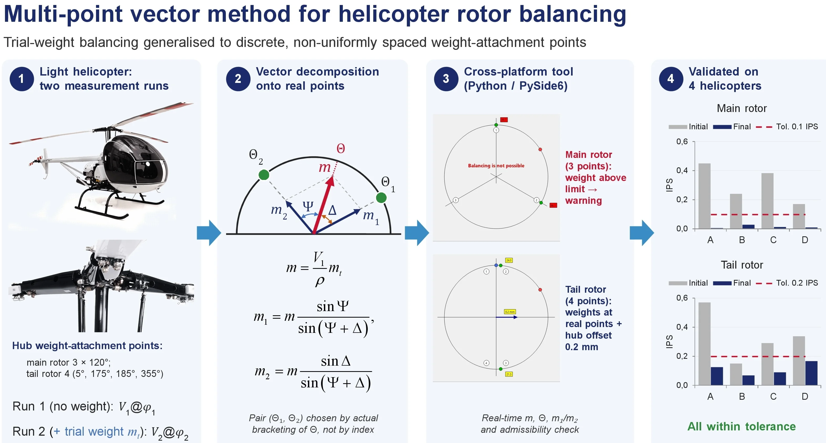
- A vector algorithm generalises trial-weight rotor balancing to any number of discrete, non-uniformly spaced attachment points, typical of real helicopter hub designs (3 points at 120° on the main rotor, 4 points at 5°, 175°, 185° and 355° on the tail rotor).
- From two measurement runs, without and with a trial weight, the corrective weight is computed and decomposed between the two real attachment points that actually bracket the unbalance angle, rather than between points adjacent by index.
- A cross-platform software tool (Python/PySide6) recomputes the corrective weight and its components in real time and checks admissibility, warning the operator when balancing is not possible with the available weights.
- For the tail rotor, the tool combines weights at the real attachment points with a predicted hub offset (0.2 mm in the example), estimated from the first measurement runs alone, which reduces the number of physical balancing iterations.
- The method and software were validated during actual ground balancing of four helicopters, bringing vibration within the 0.1 IPS (main rotor) and 0.2 IPS (tail rotor) tolerances.
1. Introduction
The source of increased helicopter vibration at the rotor rotation frequency (1/rev) is the non-uniform distribution of mass and aerodynamic characteristics of the main- and tail-rotor blades. Such vibration adversely affects the service life of airframe units, the reliability of on-board equipment, and the physical condition of the crew, so its reduction is a mandatory part of the maintenance of rotary-wing aircraft [2]. Vibration is eliminated in two successive stages: rotor tracking – aligning the paths of the blade tips in the plane of rotation by adjusting the length of the rods and the installation angles [2, 4] – and rotor balancing – eliminating the residual mass unbalance by installing corrective weights at the attachment points provided by the design. This paper considers the balancing stage under the assumption that tracking has already been performed.
The classical approach to field balancing is the trial-weight method based on influence coefficients [1]: the vibration amplitude and phase are measured during the first run, a known trial weight is installed and a second run is performed, the effect of the weight is determined from the difference of the response vectors, and the required corrective weight and its angular position are computed. Recent work continues to refine the influence-coefficient approach itself – through improved balancer hardware and dual-speed control [7], dynamic-reliability signal processing for the extracted influence coefficients [8], and its extension to multi-plane rigid-rotor balancing [9] – alongside optimisation-based methods such as [3].
A feature of helicopter rotor balancing is that the corrective weight can physically be installed only at a finite number of discrete attachment points provided by the hub design, whereas the computed angular position of the unbalance practically never coincides with any of them, and the angular intervals between the points are often non-uniform (for the tail rotor of the studied helicopter – 5°, 175°, 185°, 355°). The computed corrective-weight vector therefore has to be decomposed into two components installed at the two nearest actual attachment points. In manual (graphical) execution, which derives from the classical constructions of single-plane balancing, such decomposition is labour-intensive and introduces construction errors.
Modern research is mostly focused on optimisation and intelligent methods – genetic algorithms, neural networks, interval and probabilistic models [3, 5] – which require significant training data and computational resources. For light helicopters with a simple hub design, a direct deterministic vector method retains its practical value, provided it is correctly formalised and automated.
The aim of this work is to develop an algorithm that generalises the graphical vector method of trial-weight balancing to an arbitrary number of attachment points with non-uniform angular spacing, and to implement it as an applied cross-platform tool with visualisation of the results. The object of study is the balancing process of the main and tail rotors of a light helicopter.
2. Mathematical model of the method
The method is based on measuring the vibration-response vector of the rotor before and after installing a known trial weight. All angular quantities are given in degrees, vibration velocities in inches per second (IPS), and masses in grams. Notation: – vibration velocity, – phase angle, – trial-weight mass, – trial-weight installation angle, – angular position of the corrective weight.
2.1. Unbalance vector from two runs
The input data are two rotor runs: vibration velocity and phase during the first run (without a corrective weight) and , during the second run (with a trial weight of mass ). The vibration vector is written compactly as @; e.g. 0.24@173° denotes 0.24 IPS at a phase of 173°. Each run is a vector on a polar diagram, and in the Cartesian system the components of the response vectors are:
The influence vector of the trial weight is defined as the difference of the response vectors of the two runs, and its magnitude is computed by the law of cosines:
The trial weight is installed without prior knowledge of the location of the heavy spot and may either increase or decrease the measured vibration (Section 4.2). The method does not depend on this outcome, since it uses the vector difference of the two runs rather than the change in amplitude.
2.2. Magnitude and angular position of the corrective weight
The total corrective weight is computed as the ratio of the response magnitude of the first run to the magnitude of the influence vector, multiplied by the trial-weight mass:
The angular position of the corrective weight is determined from the direction of the influence vector, taking into account the phase of the first run and the trial-weight installation angle :
where , are the components of the influence vector. The two-argument arctangent determines the angle of the vector over the full range (−180°; 180°] and thus in all four quadrants; the obtained value is normalised to the range [0°; 360°). Accounting for the angle allows the result to be recalculated correctly for different variants of trial-weight installation.
2.3. Decomposition of the corrective weight onto discrete attachment points
Since the corrective weight is installed only at fixed attachment points, the computed weight , directed at angle , is decomposed into two components and installed at the two nearest attachment points with angular coordinates and that bracket the angle . The decomposition is performed by the parallelogram rule so that the resultant of the two installed weights coincides in direction and magnitude with the computed vector:
where and are the angles from the computed direction to the neighbouring attachment points. A key feature of the proposed approach is that the pair is selected not by consecutive indices but as the pair that actually brackets the computed angle , which makes it possible to work correctly with non-uniform angular intervals between attachment points.
2.4. Feature of tail-rotor trial-weight installation
The discreteness of the attachment points affects even the installation of the trial weight. For the tail rotor of the studied helicopter, the trial weight is not installed at a single point but is distributed symmetrically on two upper bolts on one side of the axis of rotation – at azimuths 5° and 355°, so that the resultant of the pair lies at azimuth 0°. The tail-rotor trial-weight mass in the actual balancing runs was 3-4.8 g in total on two points; for the main rotor, a trial weight of mass 20 g is installed at a single attachment point.
2.5. Reducing the corrective weight via the blade-tip attachment screws
In cases where the computed main-rotor corrective weight is too large for the hub attachment points, the mass of the blade-tip attachment screws of the “heavy” blade is changed instead through their length. Since balancing preserves not the mass but its static moment about the axis of rotation, a change of mass at the blade-tip radius is equivalent to a change of mass at the main-rotor attachment points of radius :
For the studied helicopter 3420 mm (main-rotor radius) and = 506 mm, whence the amplification factor 6.76: a change of the screw mass by only 3.6 g is equivalent to a change of about 3.6×6.76 ≈ 24.3 g at the hub attachment points, which makes it possible to compensate a large computed weight by a small physical change at the blade tip.
3. Algorithm and software implementation
The software tool implements an algorithm that generalises the model of Section 2 to an arbitrary number of discrete attachment points with non-uniform angular spacing (Fig. 1). After the quantities , and are computed by Eqs. (2)-(4) and the angle is normalised to [0°; 360°), the pair of neighbouring points that bracket the computed angle is found by scanning the actual intervals of the point array – rather than by consecutive indices – which ensures correct operation for non-uniform angular intervals. The weight is then decomposed by Eq. (5), the critical component is checked against the established threshold values, and the result is visualised together with a recommendation on the required hub offset. This approach works regardless of the number of attachment points and the uniformity of their arrangement, so different rotor types are handled without changing the computational core.
Fig. 1Flowchart of the multi-point vector balancing algorithm

The tool is built on the principle of separating the computational core from the interface layer: the core implements the mathematical model and the algorithm as a standalone function, while the interface layer is responsible only for data input, visualisation, and interaction with the user. The computational core was implemented successively in two languages – VB.NET and Python/PySide6; the migration to Python ensured compatibility with modern operating systems and cross-platform operation of the tool. The event-driven graphical interface recomputes and updates the result in real time whenever any input parameter changes.
The distributed weights are displayed at the attachment points with colour coding corresponding to the range of critical-weight values, together with a recommendation on the required hub offset. When the computed weight exceeds the technologically admissible limit, a warning is issued that balancing is not possible by the available means, which allows the operator to assess the result quickly without additional calculations.
4. Results and discussion
4.1. Verification of the computational core
The correctness of the computational core was verified by comparing its results with values obtained by the established procedure, for reference cases covering both modes and different positions of the unbalance, including boundary and symmetric ones; both implementations (VB.NET and Python) were checked automatically by regression tests. The discrepancies in the corrective weight, its angular position, and the distributed components did not exceed the rounding error (0.1 g in mass and 1° in angle). Table 1 gives characteristic data sets.
4.2. Results of actual balancing
The method was applied during ground acceptance tests of four helicopters (items A–D; serial numbers and dates anonymised). Each balancing followed the scheme of the method – first run, second run with a trial weight, and a check run after installing the corrective weights, repeated as needed. The generalised results are given in Table 2.
Table 1Verification of the corrective-weight calculation and its distribution
Rotor | 1st run | 2nd run | , g | , g | , ° | , g |
Main | 2.20@10° | 2.00@358° | 20 | 91.3 | 60 | 91.6 / 90.9 |
Tail | 2.20@10° | 5.90@78° | 4 | 1.6 | 270 | 9.2 / 9.2 |
The vibration vector is in the @ format, IPS; for symmetric positions (last row) the weights are distributed equally | ||||||
Table 2Results of helicopter rotor balancing by the trial-weight method
Item | Rotor | Initial @ | , g | Final , IPS | Tol. | Additional actions |
A | Main | 0.45@33° | 20 | 0.007 | 0.1 | change of blade-tip screw mass |
Tail | 0.57@218° | 4.8 | 0.127 | 0.2 | hub offset and rotation, 5 iterations | |
B | Main | 0.24@173° | 20 | 0.03 | 0.1 | – |
Tail | 0.15@78° | 3 | 0.07 | 0.2 | – | |
C | Main | 0.383@284° | 20 | 0.014 | 0.1 | change of blade-tip screw mass |
Tail | 0.29@233° | 4 | 0.091 | 0.2 | – | |
D | Main | 0.17@134° | 20 | 0.011 | 0.1 | – |
Tail | 0.338@326° | 3 | 0.168 | 0.2 | hub offset (shims 1.8 and 2.2 mm) | |
The vibration vector is in the @ format, IPS | ||||||
For all items, the final vibration level was brought within the established tolerance (0.1 IPS for the main rotor, 0.2 IPS for the tail rotor); the general requirements for the balance quality of rigid rotors are regulated by [6]. For items A and C the computed main-rotor weight was too large, so the blade-tip screw-mass technique of Section 2.5 was applied. Tail-rotor balancing sometimes required several iterations; the most illustrative is item A (Table 3).
Iteration 2 did not meet the requirements, illustrating the iterative nature of the process, and iteration 3 is also characteristic: since offsetting the hub within ±0.1 mm gave no satisfactory result, the engineer departed from the program’s recommendation and rotated the hub by 180° – a choice based on balancing experience rather than calculation alone.
Table 3Iterative course of tail-rotor balancing of item A
Iter. | Initial @ | Calculation | Recommendation | Action taken | Result , IPS |
1 | 0.57@218° | 2.1 g at 319° | hub left 0.1 mm | hub offset left by 0.1 mm | (to iter. 2) |
2 | 0.41@135° | 1.5 g at 38° | – | install weights 5.8+4.6 g | 0.23 – fails spec |
3 | 0.44@131° | 1.6 g at 42° | hub right 0.1 mm | rotate hub by 180° | (to iter. 4) |
4 | 0.49@62° | 1.9 g at 109° | hub right 0.1 mm | hub offset right by 0.1 mm | (to iter. 5) |
5 | 0.113@252° | 0.4 g at 289° | – | install weights 2.3+2.2 g | 0.127 – within tol. |
The vibration vector is in the @ format, IPS | |||||
4.3. Discussion
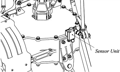
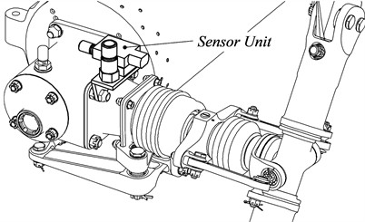
The input data (vibration velocity and phase) were obtained with standard equipment containing an accelerometer and a photo tachometer; two instruments were used – the DSS Personal MicroBalancer and the DSS MicroVib II Aircraft Analyzer – and in the authors’ experience the measurements of the former proved more stable. The accelerometer and photo tachometer were combined in a single sensor unit mounted on the gearbox casing of each rotor (Fig. 2), with the tachometer channel aimed at a reflective mark on the hub of each rotor to provide the once-per-revolution reference signal; data were acquired at the nominal rotor speed under steady ground-run conditions. Tail-rotor balancing was generally more difficult than main-rotor balancing and for some items required an additional hub offset – by spacer shims (item D) or by transverse offset and rotation (item A). The relationship between the computed corrective weight and the required hub offset was established experimentally and embedded in the tool as threshold values, so the program predicts the need for an offset and its approximate magnitude from the first runs alone, before physical iterations; this empirical component distinguishes the approach from purely computational methods.
Compared with the manual graphical method, the tool removes construction errors, automatically finds the pair of attachment points for decomposition, and improves the speed and reproducibility of the calculation. Unlike known computerised track-and-balance tools, which typically present the result on a polar diagram and do not decompose the corrective weight between discrete attachment points with non-uniform angular spacing, the proposed approach performs this generalised decomposition and additionally predicts the hub offset, which constitutes its main distinction. The method is limited to designs with discrete attachment points and assumes prior tracking; a promising direction is its integration with measuring equipment for automatic input of vibration data.
Fig. 2Sensor unit installation: a) main-rotor gearbox; b) tail-rotor gearbox. Courtesy of DB Aerocopter LLC, Poltava, Ukraine
a)
b)
5. Conclusions
1) An algorithm has been proposed that generalises the classical graphical vector method of trial-weight balancing to an arbitrary number of discrete attachment points with non-uniform angular spacing, and a software tool has been developed that automates the calculation and distribution of the corrective weight for the main (three points) and tail (four points) rotors, with visualisation and assessment of balancing admissibility.
2) The correctness of the computational core was confirmed against the established procedure – the discrepancies did not exceed 0.1 g in mass and 1° in angle – so the tool reduces calculation time and eliminates the errors of manual graphical construction.
3) The method was validated during actual balancing of four helicopters; the final vibration level was brought within the tolerances of 0.1 IPS (main rotor) and 0.2 IPS (tail rotor). Tail-rotor balancing proved more complex and in some cases required an additional hub offset or rotation, which the tool predicts from the first runs. A practical technique was also described for compensating an excessively large main-rotor corrective weight through the blade-tip attachment screws (equivalence factor 6.76). A promising direction of development is the integration of the tool with measuring equipment for automatic input of vibration data.
References
-
L. Tao, “A practical one shot method to balance single-plane rotor,” American Journal of Mechanical Engineering, Vol. 11, No. 3, pp. 103–106, Jun. 2023, https://doi.org/10.12691/ajme-11-3-1
-
A. Rosen and R. Ben-Ari, “Mathematical modelling of a helicopter rotor track and balance: theory,” Journal of Sound and Vibration, Vol. 200, No. 5, pp. 589–603, Oct. 2002, https://doi.org/10.1006/jsvi.1996.0669
-
C. Wang, G. Huang, F. Li, G. Yu, H. Yi, and H. Peng, “A novel constrained optimal tuning method with application to helicopter rotor track and balance,” Mechanical Systems and Signal Processing, Vol. 184, p. 109715, Sep. 2022, https://doi.org/10.1016/j.ymssp.2022.109715
-
M. J. Renzi, “An assessment of modern methods for rotor track and balance,” Air Force Institute of Technology, Wright-Patterson AFB, 2004.
-
E. Bechhoefer, A. Fang, and D. van Ness, “Improved rotor track and balance performance using an expert system,” in IEEE Conference on Prognostics and Health Management, pp. 1–8, 2011, https://doi.org/10.1109/icphm.2011.6024337
-
“Mechanical vibration – rotor balancing – Part 11: procedures and tolerances for rotors with rigid behaviour,” ISO 21940-11:2016, 2016.
-
P. K. Gharehcheloo, F. F. Saberi, and M. Shamshirsaz, “Design and validation of a high-speed rotor balancer based on influence coefficient method and dual-speed control,” Scientific Reports, Vol. 16, No. 1, Feb. 2026, https://doi.org/10.1038/s41598-026-38071-z
-
J. H. Jung, B. Kim, W. J. Na, and Y.-H. Shin, “Development of rotor balancing algorithm for a high-precision rotor system considering dynamic reliability through automatic-adaptive DBSCAN,” Structural Control and Health Monitoring, Vol. 2024, No. 1, 2024, https://doi.org/10.1155/2024/6150717
-
S. Gupta and H. Chaudhary, “Influence coefficient method for rigid rotor balancing in multi-plane,” in Lecture Notes in Mechanical Engineering, Singapore: Springer Nature Singapore, 2025, pp. 89–103, https://doi.org/10.1007/978-981-96-7011-6_7
About this article

The authors have not disclosed any funding.
The datasets generated during and/or analyzed during the current study are available from the corresponding author on reasonable request.
The authors declare that they have no conflict of interest.

