Abstract
Layered structural materials are widely used across many sectors. Under external loads and long-term operation, internal and interfacial cracks, delaminations, and other defects may develop within these materials, reducing structural durability and potentially leading to premature failure. The acoustic emission (AE) method enables the detection of such defects during their formation and growth by recording elastic waves that propagate through the material and cause surface oscillations. For the AE method, evaluating the displacement field on the solid surface is of primary importance. This paper presents the analytical solution to the 3D dynamic problem of determining the displacement field on the surface of an elastic three-layered composite under steady oscillations of internal penny-shaped Mode III cracks. The problem is reduced to a system of boundary integral equations. Displacements in the body are represented through Helmholtz potentials. An integral presentation of displacements for a special case of a three-layer composite is obtained – on the surface of a layer placed in a half-space with a crack (two layers have the same properties). The paper analyzes numerical results based on the analytical solution in detail. The dependence of displacement on the elastic characteristics of the components, the frequency of crack-surface displacement, the distance between the observation point and the fracture epicenter, and the crack depth in the two-component body has been established.
Highlights
- The general solution to the 3D dynamic problem of determining the displacement field on the surface of an elastic three-layered composite for steady oscillations of the surfaces of internal penny-shaped Mode III cracks is obtained.
- The problem is reduced to a system of boundary integral equations, and displacements in the body are represented through Helmholtz potentials.
- Numerically, the dependence of displacement on the two-layer composite’s surface on the elastic characteristics of the components, the frequency of crack surface displacement, the distance between the observation point and the fracture epicenter, and the crack depth has been established.
1. Introduction
Layered structures are widely used across many sectors, including the oil, energy, chemical, aerospace, and shipbuilding industries, as well as civil engineering. External loads and prolonged operation can induce internal and interfacial cracks, delamination, and other defects in these materials, reducing their durability and leading to premature failure. The acoustic emission (AE) method detects such defects during their formation and growth by recording elastic waves that propagate through the material and cause surface oscillations [1]. In AE non-destructive testing (NDT), evaluating surface displacement parameters is important because AE transducers directly record these displacements during inspections.
Solving many scientific and technical problems requires studying the laws of elastic wave propagation in media with complex physical and mechanical properties and heterogeneous structures [2-5]. It is important to consider the influence of structural inhomogeneities (inclusions, cracks, cavities, etc.) when studying the material. Under various loads (impact, cyclic), defect initiation or development causes damage accumulation that threatens the object’s integrity [6, 7].
The determination of stress intensity factors under static loading serves as a basis for assessing a material’s resistance to fracture. The characteristics of the wave field in bodies with a layered structure are analyzed using different approaches, including the Fourier integral transform method and dual integral equations [8], a boundary-element-based method [4], the finite element method [9, 10], and the extended consecutive-interpolation finite element method [11].
At the same time, dynamic loads significantly impact the structural integrity of layered composite structures. The time-periodic nature of the applied load results in complex stress and displacement wave patterns throughout the body. Numerous studies have addressed stress analysis primarily focused on two-layer structures with various defects under dynamic loading [12]. Due to significant mathematical and computational challenges, limited research has addressed the propagation of elastic waves in multi-layered heterogeneous structures under dynamic loading. We are not aware of any analytical studies of the displacement field on the surface of layered structures with internal cracks.
The traditional analytical approach for calculating the stress-strain state of a cracked solid body consists of two stages: (1) determining the crack opening displacement (COD) functions under the applied load on the crack faces; and (2) calculating the dynamic stress intensity factors (DSIF) and displacements within the body. However, for complex structures, obtaining analytical solutions at the first stage is often not feasible, and the accuracy of numerical simulations depends heavily on the reliability of the model’s input parameters.
For the investigation of acoustic waves in infinite domains with defects, the boundary integral equation method has demonstrated good suitability [1]. Previously, we proposed a method for estimating surface displacements induced by crack opening, where the COD functions are prescribed in advance [13]. This simplified modeling approach, combined with the boundary integral equation (BIE) method, enables a qualitative assessment of displacements within the solid and on its surface.
This study aims to model the propagation of elastic waves induced by displacements of opposite faces of penny-shaped Mode III cracks in a three-layer structure using the boundary integral equation method, enabling a qualitative analysis of the resulting surface displacement field.
2. Mathematical problem
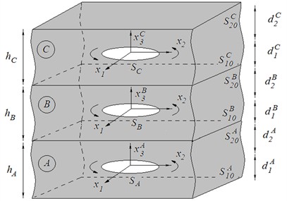
Let us consider the solid body from three isotropic layers , , of thickness , , , respectively (Fig. 1). The materials of the layers have the mass densities , Poisson’s ratios , and shear moduli , where . Each layer contains a flat penny-shaped crack of radius with a fixed contour and area . The cracks are parallel to the layer surface, and their centers lie on the same line. We chose the local coordinate system in the region so that the origin of coordinates coincides with the center of the crack, and the axes , are in the plane of the defect.
Fig. 1General geometry of the layered composite with the penny-shaped cracks
The opposite surfaces of the cracks are subjected to shear torsional displacements, which vary in time according to a harmonic law with frequency and are described by the COD functions:
where is the radial coordinate; is the imaginary unit. It is assumed that the contour of the cracks is fixed, and there is no contact between the crack surfaces during displacement. It is necessary to determine the parameters of the wave field of displacements in the body based on the given COD functions.
Fig. 2Crack location and selection of the coordinate system in layer D
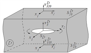
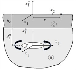
Fig. 3Diagram of the location of a disk-shaped crack in a half-space B
With the specified method of arrangement of cracks in the body and the type of opening of their surfaces, only horizontally polarized transverse waves (SH waves) will propagate in the composite [14]. The problem is reduced to solving differential equations with respect to the amplitude values of the displacement vector, which for layer (Fig. 2) have the form:
where is the three-dimensional Laplace operator; is the displacement vector amplitude; is the wave number; is the velocity of transverse elastic wave in the layer .
Eq. (2) must be solved for three groups of boundary conditions, which we formulate only for the amplitudes of shear displacements and tangential stresses.
Group І: boundary conditions on crack surfaces:
Group ІІ: the conditions of ideal mechanical contact are met on the interface surfaces of the layers:
Group ІІІ: the lower surface of layer and the upper surface of layer (Fig. 1) are free from loads:
The total displacement field in layer is given as the sum:
where are the displacements from oscillations of points on the lower surface of the layer; are the displacements from oscillations of points on the upper surface of the layer; are the displacements from the opening of the crack surfaces .
To solve the problem, we use the BIE method. We write the displacement in the form:
where:
are the Helmholtz potentials; unknown densities characterize the displacement of surface points of the layer D; is the distance between the fixed point and the point of integration areas or . The representation of the displacements in the form Eqs. (7), (8) automatically satisfies the Helmholtz Eq. (2) and the Sommerfeld radiation conditions at infinity [15].
3. Problem solution
The solution algorithm of the problem in general formulation is as follows. In the first step, using Eqs. (6)-(8), the displacements in layer relative to the coordinate system , associated with the lower surface of the layer, and relative to the coordinate system , associated with the upper surface of the layer, were written. Next, the boundary conditions Eq. (4) and (5) of the problem, considering the obtained representations, were written. Boundary conditions form a system of 12 two-dimensional BIEs of the Helmholtz potential type for the unknown densities , , . The right-hand sides of the equations are determined through known given COD functions. To solve the BIEs, we apply to them the two-dimensional integral Fourier transform with respect to the variables , , the convolution theorem [16], and some values of the Fourier transforms. As a result, we obtained a system of linear algebraic equations; the solutions of the system are the Fourier transform expressions of the desired functions. After applying the inverse Fourier transform to these solutions, we obtained integral representations of the desired functions. To determine the displacements in layer , a series of algebraic transformations was performed using the values of some integrals [16, 17].
The final expression for angular displacements in layer initiated by the CODs in the layers , , of the layered composite is written as:
4. Results and discussions
To verify the proposed numerical method and analyze the basic patterns, a numerical solution was obtained for the case of a layer perfectly bonded to a half-space (Fig. 3). A half-space is formed here, provided that two layers ( and in Fig. 1) have identical properties. An analogue of this structure may be a layered composite formed by applying a coating (for example, galvanic) to a structurally homogeneous element of significantly larger geometric dimensions than the coating’s thickness. To proceed to such a problem from the general representation Eq. (9) for displacements, we assume that 0, , 0, 0, 2, 1, , .
The integral representation for displacements on the surface of layer takes the form:
where , , , .
Note that for identical materials of the half-space and the layer, relation (10) reduces to displacement relations for a half-space with a crack at a depth [18].
For the function in the denominator of Eq. (10) has no real zeros, and the semi-infinite integral was split into three integrals with the following limits during the calculation , and . The choice of radical branches is determined by the need to satisfy the Sommerfeld radiation conditions:
The integrals were solved using Gaussian elimination on the first two intervals with 40 nodes and Laguerre quadrature on the third interval with 60 nodes [19].
For , the semi-infinite integral Eq. (10) was divided into three intervals with the following limits: , and . For the first two intervals, the integral was calculated using the trapezoidal method along the Sommerfeld contour with 40 equally spaced nodes [20]. On the third interval, the integral was calculated using Laguerre quadrature with 60 nodes.
According to Eq. (10), the normalized displacement amplitudes relative to the layer thickness were determined for different wave numbers and the parameter , which characterizes the stiffness ratio of the layers’ materials.
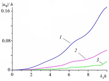
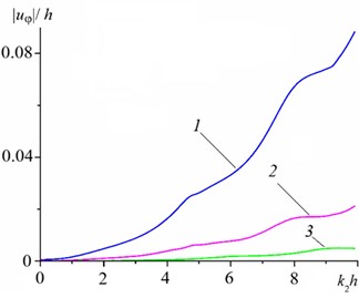
Fig. 4 shows the dependence of normalized displacements on the surface of layer (Fig. 3) on the wave number at the observation point of for different and various crack depths at the half-space. The crack has a radius of , curve 1 – ; curve 2 – ; curve 3 – . The graphs show that, regardless of the ratio of the materials’ stiffnesses, the maximum displacement amplitudes on the layer surface decrease with increasing crack depth in the half-space. If the layer material has greater stiffness, then with its increase, the local maximum of the amplitudes of displacements on its surface increases, shifting towards lower frequencies (Fig. 4(a)). If the material of the half-space has greater stiffness, then with its increase, the local maximum of the amplitudes of displacements on its surface decreases, shifting towards lower frequencies (Fig. 4b).
Fig. 5 shows the dependence of the normalized displacements on the distance from the observation point for different , with a fixed oscillation frequency of . The crack depth is equal to the crack radius of . The distance from the epicenter of the fracture varied in the range 0,…, 10 with a step of 0.2.
Fig. 4Dependence of normalized displacements on the layer C surface at the point above the crack contour on the wave number for various crack depths d2B in the half-space for different ratios of the stiffness of the layer and half-space materials: а) G= 2; b) G= 1/2
a)
b)
Fig. 5Dependence of normalized displacements on the distance r to the observation point on the layer C surface for different ratios of stiffness of composite components
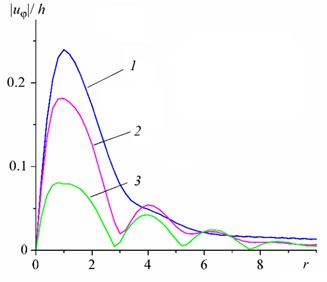
a) Curve 1 – 2; curve 2 – 10; curve 3 – 100
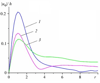
b) Curve 1 – 1/2; curve 2 – 1/10; curve 3 – 1/100
Regardless of the ratio of the body components’ stiffnesses, the amplitudes of displacements on its surface at the selected frequency are greatest if the distance from the epicenter of the fracture is equal to the layer thickness; with further distance from the epicenter, they gradually decrease and disappear. The increase in the stiffness of the layer and half-space materials reduces the displacement amplitudes. For example, with a 5-fold increase in the stiffness of the half-space, the maximum amplitude of the displacements decreases by 25 % (curves 1 and 2 in Fig. 5(a)), and with a 5-fold increase in the stiffness of the layer, the maximum amplitude of the displacements decreases by 38 % (curves 1 and 2 in Fig. 5(b)).
5. Conclusions
The solution to the 3D dynamic problem of determining the displacement field on the surface of an elastic three-layered composite for steady oscillations of the surfaces of internal penny-shaped Mode III cracks is obtained.
Numerically, the dependence of displacement on the two-layer composite’s surface on the elastic characteristics of the components, the frequency of crack surface displacement, the distance between the observation point and the fracture epicenter, and the crack depth has been established.
References
-
V. Skalskyi, Z. Nazarchuk, and O. Stankevych, “Macrofracture of structural materials and methods of determining its type,” in Foundations of Engineering Mechanics, Cham: Springer International Publishing, 2022, pp. 1–50, https://doi.org/10.1007/978-3-031-11291-1_1
-
S. Ali, X. Liu, S. Fawzia, J. Wu, and Y. T. Gu, “A review on exploring the behavior of multi-layer composite structures under dynamic loading,” International Journal of Structural and Civil Engineering Research, Vol. 5, No. 1, pp. 44–51, 2016, https://doi.org/10.18178/ijscer.5.1.44-51
-
W. Wang, S. T. de Freitas, J. A. Poulis, and D. Zarouchas, “A review of experimental and theoretical fracture characterization of bi-material bonded joints,” Composites Part B: Engineering, Vol. 206, p. 108537, Nov. 2020, https://doi.org/10.1016/j.compositesb.2020.108537
-
G. Long et al., “Analysis of crack problems in multilayered elastic medium by a consecutive stiffness method,” Mathematics, Vol. 10, No. 23, p. 4403, Nov. 2022, https://doi.org/10.3390/math10234403
-
V. Z. Stankevych and O. M. Stankevych, “Acoustic emission in elastic bimaterial with crack under different contact conditions on interface plane,” International Applied Mechanics, Vol. 60, No. 2, pp. 203–211, Jul. 2024, https://doi.org/10.1007/s10778-024-01274-w
-
Q. Dong, J. Wei, B. Zhao, and Y. Li, “Contact behaviors of multilayered structures with interfacial cracks,” Engineering Fracture Mechanics, Vol. 225, p. 106816, Dec. 2019, https://doi.org/10.1016/j.engfracmech.2019.106816
-
B. L. Wang, J. C. Han, and S. Y. Du, “Fracture mechanics for multilayers with penny-shaped cracks subjected to dynamic torsional loading,” International Journal of Engineering Science, Vol. 38, No. 8, pp. 893–901, 2003, https://doi.org/10.1016/s0020-7225(99)00068-3
-
F. Long, Z. L. Hu, X. Y. Zhang, and X. F. Li, “An interface crack model of a bimaterial plane with consideration of the induced interfacial shear stress,” Engineering Fracture Mechanics, Vol. 333, p. 111816, Dec. 2025, https://doi.org/10.1016/j.engfracmech.2025.111816
-
L. Malíková, P. Miarka, P. Doubek, and S. Seitl, “Influence of the bi-material interface on the crack propagation through a thin protective layer,” Procedia Structural Integrity, Vol. 33, No. 33, pp. 605–612, Nov. 2021, https://doi.org/10.1016/j.prostr.2021.10.067
-
N. Chi Tho, D. van Thom, P. Hong Cong, A. M. Zenkour, D. Hong Doan, and P. van Minh, “Finite element modeling of the bending and vibration behavior of three-layer composite plates with a crack in the core layer,” Composite Structures, Vol. 305, p. 116529, Nov. 2022, https://doi.org/10.1016/j.compstruct.2022.116529
-
T. T. Truong, B. K. Tran, V. S. Lo, N. T. Nguyen, and M. N. Nguyen, “Bimaterial interface crack analysis using an extended consecutive-interpolation quadrilateral element,” Vietnam Journal of Science and Technology, Vol. 60, No. 5, pp. 869–881, Nov. 2022, https://doi.org/10.15625/2525-2518/16172
-
V. Z. Stankevych, “Analysis of 3D problems of dynamic loading of elastic piecewise-homogeneous bodies with internal cracks,” Journal of Mathematical Sciences, Vol. 274, No. 5, pp. 641–659, 2023, https://doi.org/10.1007/s10958-023-06628-2
-
O. Stankevych and V. Stankevych, “Analysis of dynamic displacements in a bimaterial with a torsion crack,” in 2024 IEEE 29th International Seminar/workshop on Direct and Inverse Problems of Electromagnetic and Acoustic Wave Theory (DIPED), pp. 249–253, 2024, https://doi.org/10.1109/diped63529.2024.10706047
-
J. D. Achenbach, Wave propagation in elastic solids. North-Holland Publishing Company, 1973.
-
L. Debnath and D. Bhatta, Integral transforms and their applications. Chapman and Hall/CRC, 2016, https://doi.org/10.1201/9781420010916
-
V. Z. Stankevich, “Computation of certain double integrals that are characteristic of dynamic problems of the theory of cracks in a semi-infinite body,” Journal of Mathematical Sciences, Vol. 81, No. 6, pp. 3048–3052, 2006, https://doi.org/10.1007/bf02362592
-
I. Gradshteyn and I. Ryzhik, Table of Integrals, Series, and Products. Elsevier, 2016, https://doi.org/10.1016/c2013-0-10754-4
-
V. Skalsky, O. Stankevych, and O. Serhiyenko, “Wave displacement field at a half-space surface caused by an internal crack under twisting load,” Wave Motion, Vol. 50, No. 2, pp. 326–333, Oct. 2012, https://doi.org/10.1016/j.wavemoti.2012.09.001
-
M. Abramowitz and I. A. Stegun, Handbook of Mathematical Functions with Formulas, Graphs, and Mathematical Tables. Washington, DC, 1964.
-
L. Tsang, “Time-harmonic solution of the elastic head wave problem incorporating the influence of Rayleigh poles,” The Journal of the Acoustical Society of America, Vol. 63, No. 5, pp. 1302–1309, 1978, https://doi.org/10.1121/1.381882
About this article

The authors have not disclosed any funding.
The datasets generated during and/or analyzed during the current study are available from the corresponding author on reasonable request.
Prof. Vitalii Volodymyrovych Kovalchuk is a scientific committee member of the 78th International Conference on Vibroengineering and was not involved in the editorial review and/or the decision to publish this article.

