Abstract
The underwater acoustic reciprocity transfer function measuring method with impulse underwater sound source is studied, and time gates are utilized to eliminate the reverberant field influences on the sound pressures which are used to compute the source volume velocity. The method is validated in a lake experiment. It is showed that, the reciprocity measurement results based on the impulse source is similar to the reciprocal measurements results based on the traditional electromagnetic source, meanwhile the time cost of the impulse-based measurement is less. Thereby the measuring efficiency is boosted with an impulse source. Moreover, the reverberant field influences on volume velocity obtainments can be eliminated with suitable time gates in impulse-based measurements. Aiming at representative problems of the experiments, some suggestions about impulse-based reciprocity measurements are provided. This work may be valuable for the study of underwater sound sources and reciprocal measuring techniques.
1. Introduction
The obtainment of structural transfer functions is significant to the real-time evaluation of radiation noise. The transfer functions of complex structures, such as drilling platforms and ships, are mostly obtained with in-situ measurements. Unfortunately, the measuring methods based on actuating the structures directly, which are restricted by the narrow spaces and the friable structures, are sometimes impracticable.
The reciprocity principle provides a new way for the solution of this problem. Since the reverse of actuating points and measuring points avoids the problems above, reciprocal measuring techniques are applied in many fields. T. Ten Wolde studied the sufficient conditions of reciprocal relation, and applied the reciprocity principle in underwater transfer function measurements [1]; L. M. Lyamshev expanded the scope of reciprocity application, and studied the relation of the reciprocity principle validity and flow field, nonlinearity [2]; F. J. Fahy summarized the researches of reciprocity principle and its application in noise control [3]; Takaaki Musha used reciprocity principle to determine dominant sonar self noise sources [4]; J. M. Mencik studied blocked pressure with reciprocity principle [5]; and Oleg A. Godin combined reciprocity and waveguide [6].
However, these researches seldom force on the characteristics of the sources which used in reciprocal measuring, and even less study about the impulse-based reciprocal measuring. This paper proposes a reciprocal measuring method with impulse source. In the first section, study the practicability of the method in theory, and with the impulse characteristics, eliminate the reverberant field influences on the source volume velocity. In the second section, a lake experiment is showed and the method is validated. In the last section, the strengths and weaknesses of the impulse-based measuring method are discussed, and a conclusion is offered.
2. Basic theories
2.1. Reciprocity principle
For the transmission of structure vibration and radiation noise, the reciprocally relation shows that when keeping the surrounding constant and driving some exciting force () on the underwater structural objects, the ratio between the far-field pressure () and this exciting force equals to the ratio between the vibration velocity () at this point on structure due to a far-field source and the source volume velocity ():
The pressure , exciting force and response velocity in Eq. (1) can be measured directly, but the volume velocity, need to be calculated. The Eq. (2) for calculating the source volume velocity in free field is:
where and are the source volume velocity and the sound pressure at a distance of from the source center when the circular frequency is . is the density of the medium.
For a single structural actuating point and a single radiation noise measuring point, the reciprocity transfer function can be expressed as:
2.2. Impulse source and reverberation
If the outer sound source is an impulse sound source, the sound pressure around the sound source in time domain is an impulse signal, shown as:
where, is the amplitude of the impulse signal, is the arriving time of the impulse to the volume velocity measuring point. The relation of and can be shown as:
When the sound source is in a reverberant field, the reflective signals and scatter signals are superposed on the measuring results. Recently study showed the reverberant influences of and in Eq. (1) can be counteracted against each other [7]. So just need to consider about the influences on :
where, are the signals amplitudes of reflection and scatter in sound field, and are the transfer time of these signals.
The sound path length of reflective signals and scatter signals is larger than the direct signals’, so , ,…, . For convenient of this discussion, define , and the minimum time gap is:
Now define a time gate [8]: . When the volume velocity sound pressures are measured, just record the signals in the time gate . The signals beyond are rejected, thereby the reverberant field influences are eliminated.
3. Experiment validations
3.1. Experimental conditions
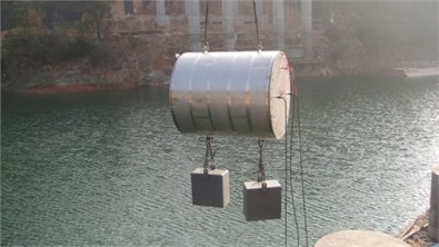
The above theory and method was validated with an experiment in a lake. The experimental structure is a double-layer cylindrical shell model, and the length of it is 2.05 m. The diameter of its outer shell is 1.78 m, and the thickness of it is 2 mm; the diameter of its inner shell is 1.46 m, and the thickness of it is 8 mm. An actuator is installed in the model. A force sensor and an accelerometer are placed at the contact point of the actuator.
Fig. 1The double-layer cylindrical shell model
The underwater impulse sound source used in this experiment is an electric spark impulse source, and an electromagnetic sound source is also used in this experiment.
Based on the theoretical analysis above, the experiment was performed according to the following steps:
(1) The model was suspended under water, and the underwater impulse source was fixed to the boat in the inlet, 5.7 m apart from the model; hydrophones were placed at four symmetrical locations around the source, each 2 m apart from it.
(2) The impulse was taken with the source; then the sound pressure response around the source and the acceleration response in the model were measured.
(3) The impulse source was withdrawn; an electromagnetic sound source was placed at the location and started with a frequency ranging from 80 Hz to 750 Hz. Likewise, measured the sound pressure response around the source and the acceleration response in the model.
(4) The electromagnetic source was withdrawn, and a hydrophone was placed at the location.
(5) The actuator was started in the model with a frequency ranging from 80 Hz to 750 Hz. The actuating force and the response radiation sound pressure were measured using the hydrophone mentioned in step (4).
3.2. Experimental results
Firstly, demonstrate the effect of time-gate operation to the experiment results. For the convenience of discussion, define the original sound pressure signals around the impulse sound source as original sound pressure signals. Likewise, define the sound pressure signals though time gates as revised sound pressure signals. As shown in Fig. 2, (a) is the original sound pressure signal in time domain; (b) is the revised sound pressure signal in time domain.
Secondly, likewise for the convenience of discussion, define the transfer functions which are obtained with the original sound pressure as original impulse-based reciprocity transfer functions (OIRTF); define the transfer functions which are obtained with the revised sound pressure as revised impulse-based reciprocity transfer functions (RIRTF); define the transfer functions, which are obtained with the measuring results of electromagnetic sound source and eliminated the reverberant influences with traditional methods, as steady-source-based reciprocity transfer functions (SRTF).
Fig. 2The sound pressure signal in time domain
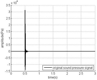
a) Original signal
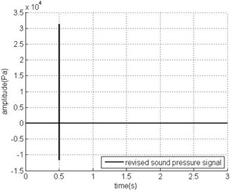
b) Revised signal
Fig. 3The reciprocity transfer functions from the radiation noise measuring point to the actuator
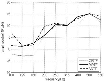
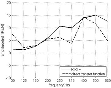
Fig. 4The RIRTF and the direct transfer function of the actuator
As shown in Fig. 3, it is found that in most frequency bands, compared with OIRTF, RIRTF is more close to SRTF. Especially in low frequency bands, the effect of the revisal is significant.
So, with data processing, the impulse-based transfer function measurements can achieve the similar accuracy as the measurements with a steady source. Moreover, for an impulse sound source, the actuating time is short, and the actuating frequency band is wide. Compared with the steady-source-based measuring time, the impulse-based measuring time is reduced and the efficiency is increased.
Lastly, compare the transfer functions of impulse-based reciprocity and direct measurement. As shown in Fig. 4, the error of RIRTF is over 3 dB in some frequency bands, the complex measuring environment of shallow water perhaps contributes to it.
4. Conclusions
In this paper, an impulse-based reciprocal measuring method is proposed, and the reverberant field influences are eliminated with impulse characteristics. An impulse source and a steady source were used in a lake experiment for the transfer functions measurements of an actuator. In most frequency bands, the gap between the measuring results of the impulse source and the steady source is less than 2 dB. When compared to the direct measuring results, the error of impulse-based reciprocity method is over 3 dB in some frequency bands. The complex measuring environment of shallow water may be the reason.
The theory and the experiment show that there are two strengths of the impulse source application:
1) It can eliminate the reverberant field influences on the volume velocity conveniently with time gates;
2) The actuating time is short, but the actuating frequency band is wide, thereby the measuring time is saved efficiently.
However, a weakness is also found in this reciprocal measuring application:
Its energy is too concentrated in time domain, so if the impulse is too weak, the signal-to-noise ratio is inadequate; if the impulse is too strong, the ranges of sensors, such as hydrophones and accelerators, are exceeded. Moreover, too strong signals perhaps result in nonlinear sound waves or vibration.
References
-
Wolde T. T. On the validity and application of reciprocity in acoustical, mechano-acoustical and other dynamical systems. Acustica, Vol. 28, 1973, p. 23-32.
-
Lyamshev L. M. Reciprocity principle and its applications in underwater acoustics. ICA 14, Beijing, 1992.
-
Fahy F. J. The vibro-acoustic reciprocity principle and applications to noise control. Acustica, Vol. 81, 1995, p. 544-558.
-
Musha T., Kikuchi T. Numerical calculation for determining sonar self-noise sources due to structural vibration. Applied Acoustics, Vol. 58, 1999, p. 19-32.
-
Mencik J. M., Champoux Y., Berry A. Development of a blocked pressure criterion for application of the principle of acoustic reciprocity. Journal of Sound and Vibration, Vol. 245, Issue 4, 2001, p. 669-684.
-
Godin O. A. Calculation of amplitudes of acoustic normal modes from the reciprocity principle. The Journal of the Acoustical Society of America, Vol. 119, Issue 4, 2006, p. 2096-2100.
-
Guo C., et al. Application and measurement of underwater acoustic reciprocity transfer functions in reverberant. Chinese Journal of Acoustics, Vol. 33, Issue 4, 2014, p. 369-378.
-
Berkhout A. J., De Vries D., Vogel P. Acoustic control by wave field synthesis. The Journal of the Acoustical Society of America, Vol. 93, Issue 5, 1993, p. 2764-2778.
About this article

This work is supported by the National Natural Science Foundation of China (51209214).
