Abstract
In view of the turbo molecular pump high-speed rotating parts, this paper presents a new machinery diagnosis method based on complex bilateral spectrum. At first, the vertical and horizontal vibration signals are directly combined into complex signals in time-domain; and then the complex bilateral spectrum is obtained by fast Fourier transform (FFT). Furthermore, the holospectrum, which can fast find machinery faults, can be obtained using the amplitude and phase at some special frequencies. At the same time, the equivalence of holospectrum technique and the proposed method is verified. Finally, a case study shows the effectiveness of the proposed method.
1. Introduction
A turbomolecular pump uses the opposite movement between high-speed spinning moving blades and static blades, which drives gas molecules from higher vacuum zone to the lower zone. Afterwards, gas molecules are pumped into the air through the backing pump to create vacuum. So far, methods like FFT amplitude spectrum [1], Orbit Center of Shaft [2], Waterfall Plot [3] continue to be widely used in fault diagnosis of high-speed spinning part. However, the amplitude and phase in methods are separate, which is not straightforward and has a greater phase difference [4]. Since the late 1980’s of last century, holospectrum [4] and Full Vector Spectrum have been continually put forward to handle the separation problem of single amplitude and phase. The core of the holospectrum technology is to conduct FFT transform [5] on signals along and directions in a bearing face of the rotor. Then the unilateral spectrum is used to integrate amplitude and phase of two directions thus the orbit of center shaft is obtained. The Full Vector Spectrum synthesizes signals along and direction into a single complex and then FFT transform is conducted. The unilateral spectrum along and direction are drawn and synthesized from the complex amplitude and phase spectrum, where the orbit of center shaft is obtained.
It can thus be seen that the holospectrum and full vector spectrum both use the unilateral spectrum of and . However, only the positive frequencies are synthesized, where the process is complicated and not straightforward. This paper presents a fault diagnosis technology based on complex bilateral spectrum analysis, where vibration signals are treated as complex and FFT transform is directly conducted. Thus fault parameters are directly obtained.
2. The principle of complex bilateral spectrum diagnosis
2.1. The kinetic model of rotor vibration [6]
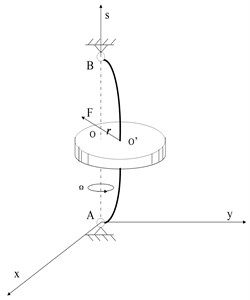
In order to determine the position center of the disk when it rotates, the fixed coordinate system is used as a reference. The coordinate of is expressed as and . Suppose the center of the rotating axis goes through the disk center and it rotates at a constant angular speed of . When the disk rotates normally, its spin axis is perpendicular. If a side shock is imposed, the flexural vibration of spin axis or side vibration of disk happens due to its resilience. The mass of the disk is expressed as . Its weight is the elastic restoring force of the spin axis:
where, is the stiffness coefficient of the spin axis, . Relative to the fixed coordinate system , the differential motion equation of the disk is:
Fig. 1Rotor model
Assume that:
The solution to the equation is:
Suppose that:
The Eq. (3) becomes:
Its solution is:
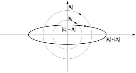
where and both are complex, which are determined by the initial side shock. The first item is an anticlockwise motion of the radius , in the same direction of the rotation angular speed , which is called forward precession. The second item is a clockwise motion of the radius , in the opposite direction of the angular speed , which is called backward precession. Both precessions synthesize the vortex motion of the disk center . Due to different initial conditions, following situations of disk center motion may occur:
1) , ; The vortex motion is forward, where its orbit is a circle and the radius is .
2) , ; The vortex motion is backward, where its orbit is a circle and the radius is .
3) ; The orbit is a straight line and the point works as a simple harmonic vibration.
4) ; The orbit is an oval. When , vortex motion is forward. When, , vortex motion is backward.
2.2. The principle of complex bilateral frequency
It can be seen from Eq. (6), that the orbit of shaft center can be uniquely determined by , and , where is the backward precession frequency. On the other side, , and can be easily determined when FFT transform is conducted on . The correspondent amplitude spectrum and phase spectrum can be obtained when matched with , and (Fig. 2). Since has both positive and negative part, it is called “bilateral frequency”. The orbit of shaft center can be further obtained and the correspondent fault parameters can thus be obtained.
Fig. 2a) Amplitude spectrum of z and b) phase spectrum of z
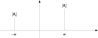
a)
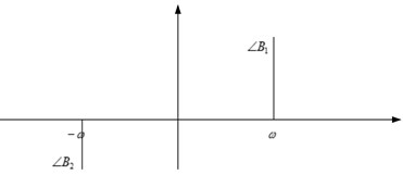
b)
Fig. 3Synthesizing diagram of shaft center orbit
3. The equivalence of complex bilateral spectrum and holospectrum
The holospectrum utilizes coefficients , in Eq. (4), and , to synthesize the orbit of shaft center. Complex vector spectrum uses and to synthesize complex and to get expression like Eq. (6). The complex coefficient and synthesize the orbit of shaft center. Essentially, they are completely equivalent and the following proof is given.
Proof: Since, the following can be obtained when is taken into Eqs. (4) and (6), then is obtained. Where:
It can be seen that Eqs. (7) and (4) are equivalent. That is to say, the bilateral spectrum of and the unilateral spectrum of and are equivalent in synthesizing the shaft center orbit.
4. Experiment verification
The experiment chooses the fault data of a molecule pump running at the speed of 10000 rpm (166.028 Hz) to analyze, where sampling frequency is 2560 Hz and data length is 1024. Fig. 4 is the time domain data sampled by the equipment developed by Beijing Air Intelligent Control Monitor Technology Institute. Fig. 5 is time domain signal of and in MATLAB. Fig. 6 is the unilateral spectrum of and signals and the bilateral spectrum of . The fault of and signal is unable to determine in the time domain. So this signal needs processing, mainly concerning orbit of particular frequencies like 1, 2, 3, 4 and correspondent parameters are extracted.
Fig. 4Time domain data sampled
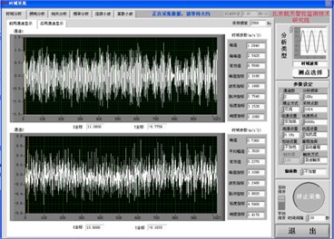
Fig. 5Time domain signals of x and y axis

Fig. 6Unilateral spectrum of x and y direction and bilateral spectrum of x+iy
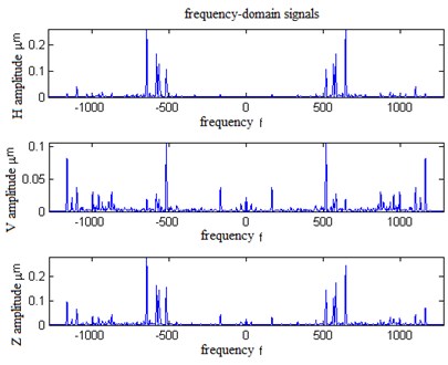
Fig. 7Correspondent holospectrum
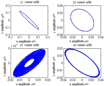
FFT transform is conducted according to the complex synthesized by and and dual frequency is obtained. It can be seen that the eccentricity of the quadruple frequency is greater and the rotor misalignment fault exists.
Meanwhile, the holospectrum [7] is used to analyze the fault, as the following shows: firstly, FFT transform is conducted on and signal to get unilateral spectrum. Then the major axis radius and minor axis radius are calculated. Afterwards, the forward and backward precession circle radius is obtained and the oval is synthesized. It is compared with the method in this paper, shown in Table 1.
Table 1Comparison of this method and holospectrum
FFT times | Precession circle radius | Oval turning direction determination | Oval synthesize | |
Complex spectrum | One | Read directly | Determine directly | Directly synthesize |
Holospectrum | Two | Indirectly calculate | Indirectly determine | Directly synthesize |
5. Conclusions
This paper puts forwards a fault analysis method based on complex bilateral spectrum. The method is not only essentially equivalent to holospectrum but also more direct and effective than it. FFT transform and spectrum correction are conducted for only one time without separate analysis of and direction. Besides, backward and forward precession parameters can be directly seen from bilateral spectrum, which directly reflects the holospectrum technology of Bently company. It is thus clear that the holospectrum technology, vector spectrum are only part of this method.
References
-
Wang Z. G., Zhu S. R. The FFT-FS spectrum refining technology and its application in machinery diagnosis. Journal of Wuhan University of Science and Technology: Science Edition, Vol. 1, Issue 23, 2000, p. 44-46.
-
Cheng H., Du L. S. The shaft center orbit fault diagnosis of rotating machinery. Journal of Taiyuan University of Technology, Vol. 5, Issue 34, 2003, p. 1-2.
-
Jiang H., Wang Y. Z. Online condition monitoring and fault diagnosis system development of rotating machinery. Oil Field Machinery, Vol. 3, Issue 34, 2005, p. 68-70.
-
Qu L. S. Holographic Diagnosis Principle of Machinery Fault. Science Press, 2007.
-
Burrus C., Parks T. W. DFT/FFT and Convolution Algorithms: Theory and Implementation. Science Press, 2007.
-
Zhong Y. E., He Y. Z., Wang Z. C. Rotor Dynamics. Tsinghua University Press, 1987.
-
Bently E., Hatch T., Grissom D. C. B. Fundamentals of Rotating Machinery Diagnostics. Bently Pressurized Bearing Press, 2002.
About this article

