Abstract
An improved physical model of stator structure with different lengths between stator core and frame is established for the vibration characteristics analysis. An analytical method is given for natural characteristics analysis, which is significantly responsible for noise and vibration reduction. The results of experimental modal analysis (EMA) and finite element method (FEM) are provided to verify the analytical method. Furthermore, considering the radial displacement of the stator core, an improved expression of electromagnetic force for coupling vibration is derived. Then the method of multiple scales is applied to solve the primary parametric vibration excited by the electromagnetic force. The influences of electromagnetic and mechanical parameters on resonance characteristic are analyzed and clearly detected by the numerical calculation.
1. Introduction
Electrical machines are one of the most fundamental motion generation mechanisms in industrial and agricultural products, even in the household electrical appliances in our daily life. Noise and vibration generate as well when the machines are working. Meanwhile, as a radiator of noise, the stator system plays an important role in the transmitting process of noise and vibration. Therefore, an accurate physical model of the stator system is essential for vibration analysis.
Researches show that the sound pressure lever and frame vibration are closely connected to both modal properties of the stator structure and frequency characteristics of the electromagnetic excitation forces [1, 2]. Thus, several physical models for the stator system are presented in previous works, such as single thin circular ring model, two concentric circular rings model, single thick cylindrical shell model [1], and two coaxial cylindrical shells named double-shell system here [3-5]. When the lengths of stator core and frame are the same, the modes are very close between double-shell model and two circular rings model in [3, 5]. Otherwise, the results are quite different.
Vibration and noise generated by an asynchronous machine can be reduced to a very large extent if the electromagnetic forces are not allowed to excite any kinds of resonances. For this reason, several analyses have been developed over the years. Ishibashi [6] studied the natural frequency and behavior of the stator by FEM, and the electromagnetic noise by boundary element method (BEM). Nahlaoui [7] presented an analytical method for fast estimation in the customizing process, and FEM for a more accurate result in the design process. On the other hand, electromagnetic forces of electric machines were analyzed by the method of Maxwell stress tensor for the vibrations in [8, 9].
The FEM for electromagnetic simulations can provide accurate solutions for the dynamic responses of an electrical machine with complicated stator and rotor shapes when the electrical machine is subjected to unbalanced magnetic forces. Meanwhile, the FEM is computationally expensive [10]. In the analytical method, the electromagnetic forces are determined by the currents, and introduced to the dynamic equations for resonance analysis. The electromagnetic behaviors have an influence on the mechanical behaviors, and the influence of the mechanical behaviors on the electromagnetic behaviors is neglected. However, in the real electrical machine, there is a mutual interaction between the electromagnetic and mechanical behaviors. Therefore, this mutual interaction must be studied in the dynamic analysis of electrical machine.
In this work, the dynamic behaviors of the stator system of the asynchronous machine are investigated when the electromagnetic and mechanical interaction is considered. Based on the improved physical model of the stator system, introducing the electromagnetic force with the stator radial displacement to the dynamic equation of the stator system, primary parametric vibration are analyzed by the method of multiple scales. Moreover, the effects of electromagnetic and mechanical parameters on resonance characteristics are analyzed.
2. Improved physical model
In this paper, a three-phase asynchronous machine is considered as a principle prototype, and its stator system is composed of stator core and frame interconnected by key bars. The stator core is considered as inner shell, and the frame is considered as outer shell of double-shell system. Especially, the length of the core is much shorter than that of the frame. Thus, the physical model is established as Fig. 1.
Fig. 1Double-shell system with unequal lengths
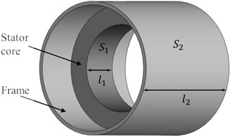
a)
b)
For a single thin shell, the displacement variational principle can be easily obtained by the Hamilton’s Principle. However, attention should be paid to the connection condition between two shells. Based on these conditions, using the method presented in [11], the vibration equation with modal damping can be obtained as:
where is the centroid radius of the stator core. The superscript is for the stator, is for the frame, and the subscript represents the orders of natural frequencies. is the mass matrix. The displacement solutions can be written as the products of periodic function and the radial mode shape function corresponding to natural frequencies based on [12]. is damping coefficient, and the frequency of double-shell system is obtained as:
where and are the frequencies of the stator core and the frame, respectively. Here, the frequencies of the complex stator structure can be calculated by this simple way. It is convenient to analyze vibration mechanism of the stator system based on this analytical model.
3. Model verification
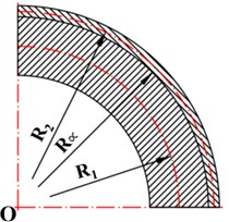
Eq. (2) is the expression of natural frequencies of double-shell system. Here, EMA and FEM are used to verify the method. Fig. 2 is the comparison of mode shapes obtained by EMA and FEM. With modal identification and numerical calculation, the calculation results of natural frequencies obtained by the analytical method (method 1), the EMA (method 2) and the FEM (method 3), are shown in Fig. 3. The margin of error between analytical solution and EMA on the first frequency is only 2.89 %, and the deviation of all results is no more than 5 %. Therefore, it can be concluded that the analytical method provides a very good match. And the double-shell stator system with unequal length can be used for further study on vibration mechanism.
Fig. 2Comparison of mode shapes
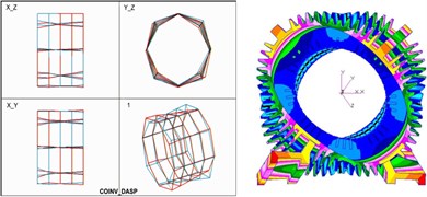
a) First-order (332.467 Hz)
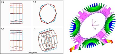
b) Second-order (522.303 Hz)
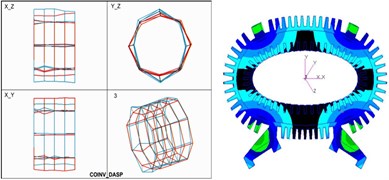
c) Third-order (580.433 Hz)
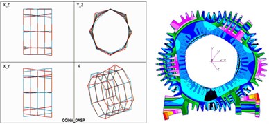
d) Fourth-order (822.653 Hz)
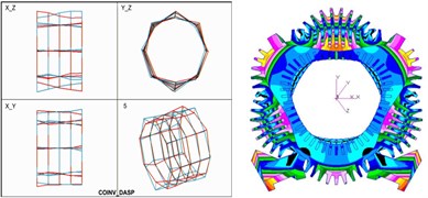
e) Fifth-order (950.473 Hz)
Fig. 3Comparison of natural frequencies
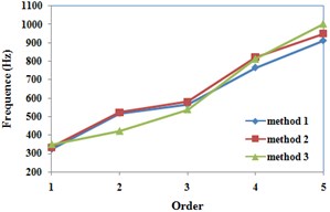
Fig. 4Comparison of models
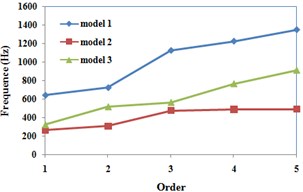
To show the precision, Fig. 4 is the comparison of three models based on [3, 5]. Both model 1 and 2 are with equal length between the stator core and the frame. The length of the stator core is stretched along the length of the frame in model 1. On the contrary, the length of the frame is compressed to the length of the stator core in model 2. The comparison indicates that the model 1 and 2 with equal length cannot represent the natural characteristics of double-shell stator system. The difference between the stator core and the frame makes the natural frequencies change a lot. The model 3 presented in this paper can take the difference in consideration.
In conclusion, by the comparison of different methods and different models, the new double-shell model can be used in a wider application range. Using this model, the vibration modes can be described by the analytical expression, and different boundary conditions between the stator core and the frame can be respectively considered. Meanwhile, the natural characteristics of the double-shell stator system with different length rates can be calculated.
4. Improved electromagnetic force
The radial electromagnetic forces that act on the stator core are evaluated by Maxwell stress based on [7, 8]:
where is the air-gap flux density, and is the vacuum magnetic permeability. It is generally commonly accepted that the tangential component is negligible in the analysis of radial vibration, as done in [13]. is air-gap magnetic performance, and is the magnetomotive force synthesized by windings, and includes fundamental component, harmonic components of stator windings and rotor windings. The air-gap magnetic performance can be improved as:
where is the average air-gap magnetic permeance, is the dimensionless radial displacement of the stator core, and is the average eccentricity.
Therefore, the expression of electromagnetic force can be derived as:
where , and are the coefficients of each component of electromagnetic force, and they are determined by the magnetomotive force . are the frequencies of electromagnetic force corresponding to . The phase angles are neglected in vibration analysis, as done in [5].
5. Magnetism and solid coupling primary parametric resonance
The vibration equation by the action of electromagnetic force has been obtained in Eq. (1). Substituting Eq. (5) into Eq. (1), the partial differential vibration equations of dynamic system with the interaction between electromagnetic and mechanical field are obtained when the order of natural frequency is equal to :
where , it is the resonance frequency of the stator system. are the coupling coefficients, which present the coupling of different mode shapes. And are the coefficients from . The subscripts , and represent the orders of mode shapes, same as .
Eq. (6) shows that the vibration equation is effected by the electromagnetic and mechanical parameters. The method of multiple scales is introduced to analyze the coupling resonance. In the case of , the stator system is on primary parametric resonance. We express the nearness of to by introducing the detuning parameter according to:
For steady-state solution, the amplitude-frequency equation can be obtained:
where is the proportional coefficient of excitation amplitude.
6. Qualitative analysis
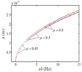
Eq. (8) shows that the amplitude is connected to the electromagnetic force , electromagnetic parameters , damping parameter , and the frequency detuning parameter . When the coupling coefficient is zero, the resonance will not be excited. Solid line represents stable solution, and dashed line represents unstable solution in Fig. 5 and Fig. 6.
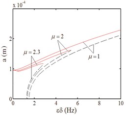
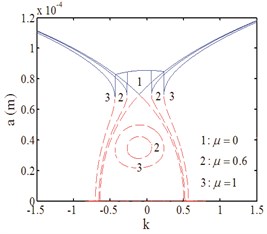
Fig. 5 is the curves that the resonance amplitude varies with excitation amplitude and damping parameter. In the case of , the resonance curves indicate that the double-shell system is excited to parametrical resonance in Fig. 5(a), and in the case of strong excitation, the resonance curves show the forced vibration characteristic in Fig. 5(b). The curves both in Fig. 5(a) and Fig. 5(b) present toward right deviation and express the hard characteristic, and the resonance region decreases with the damping parameter increasing in Fig. 5(a). Fig. 5(c) is the curves that the amplitude varies with the proportional coefficient of excitation amplitude. There is no jump phenomenon when . With the damping increasing, the resonance region is decreasing, and there are jump points when and . That means when is less than the jump point, the parametrical vibration is the main role, and the forced vibration is the leading role when is more than the jump point.
Fig. 5Amplitude-excitation amplitude curves
a)
b)
c)
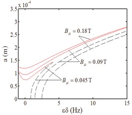
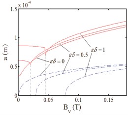
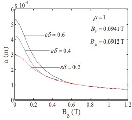
Fig. 6Amplitude-magnetic density curves
a)
b)
c)
Fig. 6 indicates the effect of electromagnetic parameters and detuning parameter on resonance response. In Fig. 6, . The resonance region is broadening with both the harmonic magnetic flux density of rotor and stator increasing in Fig. 6(a) and Fig. 6(b). When the harmonic flux density of the stator is small, its effect on the amplitude is weak. After the certain value, the effect becomes strong in Fig. 6(b). However, the fundamental component is a damping to the resonance in Fig. 6(c). And with the detuning parameter increasing, the effect becomes strong. Furthermore, the effect becomes weaker as the air-gap magnetic flux density increasing.
7. Conclusion
The improved model with unequal length between the stator core and the frame is established to study the magnetism and solid coupling vibration of the stator system as the radiator of electromagnetic noise. The results of EMA and FEM are given to verify the methodology. This double-shell model can be used to calculate the natural characteristics of the stator system with different length rates. And it can make different boundary conditions between the stator core and the frame in consideration. Furthermore, it will be used to solve the coupling vibration of stator and rotor.
The improved electromagnetic force expression reflects the interaction between electromagnetic and mechanical behaviors. This force can excite primary parametric vibration, double resonances, and the multiple resonances. These resonances are the sources of electromagnetic noise. Moreover, they can lead the asynchronous machine to accidents.
The modeling and the study on magnetism and solid coupling vibration excited by electromagnetic force lay a foundation for the design of electric machines.
References
-
Singal R. K., Williams K., Verma S. P. The effect of windings, frame and impregnation upon the resonant frequencies and vibrational behavior of an electrical machine stator. Experimental Mechanics, Vol. 30, Issue 3, 1990, p. 270-280.
-
Cho D. H., Kim K. J. Modelling of electromagnetic excitation forces of small induction motor for vibration and noise analysis. IEE Proceedings – Electric Power Applications, Vol. 145, Issue 3, 1998, p. 199-205.
-
Yamada G., Irie T., Tamiya T. Free vibration of a circular cylindrical double-shell system closed by end plates. Journal of Sound and Vibration, Vol. 108, Issue 2, 1986, p. 297-304.
-
Qing G. H., Liu Y. H., Qiu J. J., et al. A semi-analytical method for the free vibration analysis of thick double-shell systems. Finite Elements in Analysis and Design, Vol. 42, Issue 10, 2006, p. 837-845.
-
Li W. L., Qiu J. J., Yang Z. A. The double resonances of magnetism and solid coupling of hydroelectric-generator stator system. Applied Mathematics and Mechanics, Vol. 21, Issue 10, 2000, p. 1187-1196.
-
Ishibashi F., Kamimoto K., Noda S., et al. Small induction motor noise calculation. IEEE Transactions on Energy Conversion, Vol. 18, Issue 3, 2003, p. 357-361.
-
Nahlaoui M., Braunisch D., Eichinger B., et al. Calculation methods for electromagnetically excited noise in induction motors. Proceeding of Electric Drives Production Conference, 2011, p. 124-131.
-
Meessen K. J., Paulides J. J. H., Lomonova E. A. Force calculations in 3-D cylindrical structures using Fourier analysis and the Maxwell stress tensor. IEEE Transactions on Magnetics, Vol. 49, Issue 1, 2013, p. 536-545.
-
Rodríguez P. V. J., Belahcen A., Arkkio A., et al. Air-gap force distribution and vibration pattern of induction motors under dynamic eccentricity. Electrical Engineering, Vol. 90, Issue 3, 2008, p. 209-218.
-
Im H., Yoo H. H., Chung J. Dynamic analysis of a BLDC motor with mechanical and electromagnetic interaction due to air gap variation. Journal of Sound and Vibration, Vol. 330, Issue 8, 2011, p. 1680-1691.
-
Li B. Z., Zhang Q. C. The combined internal and principal parametric resonances on continuum stator system of asynchronous machine. Shock and Vibration, 2014.
-
Ghoshal A., Parthan S., Hughes D., et al. Free vibration characteristics of cylindrical shells using a wave propagation method. Shock and Vibration, Vol. 8, Issue 2, 2001, p. 71-84.
-
Pennacchi P., Frosini L. Dynamical behaviour of a three-phase generator due to unbalanced magnetic pull. IEE Proceedings – Electric Power Applications, Vol. 152, Issue 6, 2005, p. 1389-1400.
About this article

