Abstract
The paper presented the issues related to the study of the alar cast partial. For this purpose, the author’s test station with a dedicated measurement system (with particular emphasis on its dynamics).
1. Introduction
Many research centres in the country and abroad are engaged in mathematical modelling of dental prostheses. The most famous centres include the Institute of Dentistry of Medical University of Warsaw. However, the works conducted there are limited to static loads of the analysed biomechanical prosthesis systems. Thus, there is a need to extend the research and make the comprehensive assessment and mathematical analysis of the dental prosthesis behaviour (both with the static and kinematic extortion [1, 2] with regard to the gum soft tissue model). Such research were conducted at the Institute of Electronic Systems of the Military University of Technology.
Mathematical models of dental prostheses are a tool that allows to obtain great cognitive abilities [3]. They allow to fully observe (deformation and stress) of each area of the dental prosthesis, with any external extortion [4]. They also make it possible to observe and assess the durability of the prosthesis, during the prolonged usage. However, this tool is relatively difficult to the rapid production, usually complicated to use and most often quite expensive. It is also not suitable to be commonly used without prosthodontists.
While biting the food, the effective load rate of each tooth is in the range of 40-120 cycles/min [5, 6]. The static loads of the effective pressure exerted then on the occlusal surface of the tooth do not exceed 20 N.
During the initially conducted measurements and simulation on a flat model of the prosthesis, it was found that regardless of the location of the (tooth) force application, both deflection and deformation of the metal plate of the prosthesis are linearly dependent on the forces of the values to 15 N [7, 8].
The estimated value of deflection should not exceed 5 mm [9]. However, it is more difficult to accurately estimate the deformation values which will occur during the tests, because it is mainly dependent on the place of its measurement of the prosthesis. It can be assumed the deformation values should be in the range of ±300 µm/m. Despite the adoption of the above assumptions as to the limits of measurements, the systemic concept of the measurement system afforded the opportunity to significantly expand the measurement range so that the measurements were possible for external forces with values up to 20-25 N [10, 11].
2. Cast partials testing
The aim of the research is to conduct the laboratory observation of the alar cast partial under the dynamic load. The analysed testing prosthesis (Fig. 1) is a replica of the clinical prosthetic restoration that was made and successfully applied in the patient suffering from the lack of the 6th teeth.
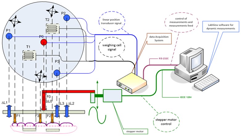
The author’s specialist measurement station was made for the purposes of the research analysis which is aimed at identifying and measuring the prosthesis model behaviour under the influence of the dynamic load. It is shown in Fig. 2. When designing this station, the particular attention was paid to the diagnostic signals [12] and the reliable operation [13] (both in terms of power supply systems [14, 15] as well as the impact of electromagnetic interference [16, 17]) by using appropriate reliability structures. During the design of the laboratory station, a manner of the force application, direction and variability in time [18, 19].
Fig. 1Test prosthesis with highlighted load application points (23-27)
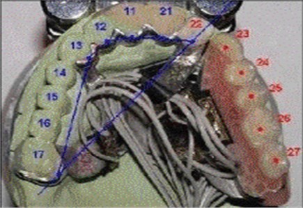
Fig. 2Diagram of test station
In the analysed system, the variable forces, which cause deflection and deformation of the tested dental prosthesis, have a sinusoidal character, and their frequency does not exceed 2 Hz. The used measuring transducers and the amplifier have an influence on the dynamic properties of the measurement chain. The latter one is designed to process signals of the frequencies to 4.8 kHz. Therefore, it can be assumed that the measuring transducers play a key role in the dynamics of the system.
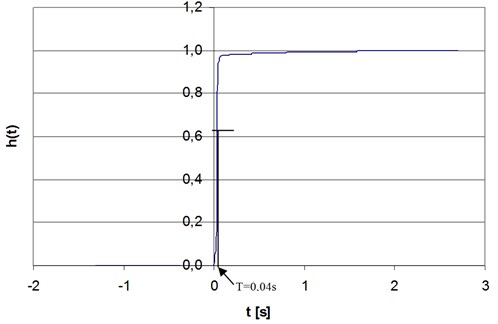
In order to measure the deflection, the potentiometric transducer was applied. It includes an internal spring which ensures the contact reliability of the movable element with the potentiometer slide. The potentiometer itself, by definition, can be treated as an inertia-free element, however, the spring (energy storage element) changes the nature of this transducer into the inertial one. The experiment was conducted, giving the unit step function to the input of the deflection transducer. The response to the unit step function is shown in the Fig. 3.
The nature of the response allows to classify this transducer as the first-order inertial element. The determined time constant value 0.04 s allows to specify the phase shift introduced by the transducer according to the Eq. (1) [20]:
The phase shift introduced by this transducer, for the frequency of 2 Hz, is 0.46 rad.
The study of the response to the unit step function allows to approximately determine the upper corner frequency of the element in accordance with the Eq. (2) [20]:
Fig. 3The response of the potentiometric transducer of linear shifts to the unit step function
In this case 8.75 Hz. It means that in the DC-2Hz frequency band, the amplitude response is flat, and the transducer does not introduce the amplitude distortion.
In order to measure the deformation, the tensometric transducers of the Hottinger Baldwin Messtechnik GmbH Company were used. The tensometric transducer itself, in the above frequency band, based on the manufacturer’s data, can be treated as an inertia-free transducer. In the measurement system, a single strain gauge is stuck in the selected location of the prosthesis and allows to measure deformation, which occurs in the area of its resistive grid. The dynamic properties of the section of the strain gauge-tested element mainly depend on the location in which the strain gauge is stuck on the prosthesis. The tested area of the prosthesis, depending on the location, may have a different nature.
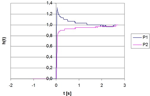
As in case of the deflection transducer, two (stuck in different location) strain gauges were subject to extortion in the form of the unit step function.
Strain gauges were stuck symmetrically to the prosthesis base, including the P1 prosthesis on the side of artificial teeth, and the P2 transducer on the side of the support clip. As it is seen in Fig. 4, the tested element with the P1 transducer shows the second order oscillating nature with dying oscillation, and the element with the P2 transducer presents the inertial nature. It is compatible with the theoretical predictions because the P1 transducer, which is fixed at a greater distance from the point of rigid mounting of the prosthesis, together with the spring element, form approximately a long curved beam, which responds to the simulation of the unit step function with the dying oscillation.
The above tests confirm that the same strain gauge as the inertia-free element can be used to measure the deformation of the selected areas of the dental prosthesis. The deformation of the tensometric grid, accurately without the phase shifts and amplitude deformation, repeat the deformation of the tested part of the dental prosthesis.
Fig. 4The response of the tested elements of the prosthesis with the strain gauges to the unit step function
3. Conclusions
The paper presented the issues related to the study of the actual alar cast partial. For this purpose, the functioning of this type of prostheses, with the particular emphasis on forces and stresses that occur there, were analysed. It allowed to prepare the measurement station, which makes it possible to measure the prosthesis model deformation under the influence of the dynamic load. The aspects related to the dynamics of the measurement system were also presented. In the further research, the experiments, which allow to visualise the shift and deformation signals as well as functional dependencies between the recorded values (using the computer assistance in the form of the LabView software package), were conducted.
References
-
Kuchta M., Chwaleba A., Gryszkiewicz M. Experimental verification of deflection backbone modeling dentures with separate kinematics. X School Computer-Aided Design, Manufacturing and Maintenance, Jurata, 2006, p. 91-97, (in Polish).
-
Kuchta M., Szulim M. Electronic measurement set for diagnostic dentures with dynamic excitations. Przeglad Elektrotechniczny –Electrical Review, Vol. 12b, 2011, p. 96-100, (in Polish).
-
Kuchta M., Siergiejczyk M., Paś J. FEM analysis of arch cast partials. Journal of Vibroengineering, Vol. 16, Issue 8, 2014, p. 4039-4044.
-
Kuchta M., Wnuk M. Modeling elastic support dentures. Electrical Review, Vol. 12, 2010, p. 79-82, (in Polish).
-
Henderson D., Mcgivney G. P., Castleberry D. J. McCracken’s Removable Partial Prosthodontics. C.V. Mosby Co., St. Louis, 1985.
-
Hupfauf L., Niedermeier W. Partial Dentures. Kinematics of dentures, Urban and Partner, Wrocław 1997, (in Polish).
-
Michalski W., Michniowski Z., Kuchta M., Chwaleba A. Numerical simulation of mechanical behavior and reactions of the wing base of the upper denture – model flat. Protetyka Stomatologiczna – Prosthodontics, Vol. 3, 2005, p. 197-206, (in Polish).
-
Niedermeier W. For Storage Behavior Rigidly Supported Out Prostheses. Deutsche Zahnärztliche Zeitschrift, 1980.
-
Kydd W. L., Daly C. H., Wheeler J. B. The thickness measurement of masticatory mucosa in vivo. International Dental Journal, Vol. 21, Issue 4, 1971, p. 430-441.
-
Kuchta M., Kwiatos K., Fokow K. Set-up diagnostic tests dentures. Diagnostics, Vol. 3, Issue 39, 2006, p. 187-193, (in Polish).
-
Michalski W., Kuchta M., Fokow K. Tensometric experimental measurements of mechanical wing for the numerical simulation of dentures. Materials Conference VII Symposium on Modeling and Measurement in Medicine, Krynica, 2005, p. 197-203, (in Polish).
-
Dabrowski T., Bednarek M., Fokow K., Wisnios M. The method of threshold-comparative diagnosing insensitive on disturbances of diagnostic signals. Przeglad Elektrotechniczny – Electrical Review, Vol. 88, Issue 11A, 2012.
-
Siergiejczyk M., Paś J., Rosiński A. Evaluation of safety of highway CCTV system’s maintenance process. The monograph „Telematics – support for transport”, Springer-Verlag, Berlin Heidelberg, Vol. 471, 2014.
-
Rosiński A. Reliability-exploitation analysis of power supply in transport telematics system. In the Monograph Safety and Reliability: Methodology and Applications – Proceedings of the European Safety and Reliability Conference ESREL 2014, Balkema Press, London, 2015, p. 343-347.
-
Rosinski A., Dabrowski T. Modelling reliability of uninterruptible power supply units. Eksploatacja i Niezawodnosc – Maintenance and Reliability, Vol. 15, Issue 4, 2013, p. 409-413.
-
Duer S., Zajkowski K., Duer R., Paś J. Designing of an effective structure of system for the maintenance of a technical object with the using information from an artificial neural network. Neural Computing and Applications, Vol. 23, Issues 3-4, 2013, p. 913-925.
-
Paś J., Duer S. Determination of the impact indicators of electromagnetic interferences on computer information systems. Neural Computing and Applications, Vol. 23, Issues 7-8, 2013, p. 2143-2157.
-
Burdzik R. Implementation of multidimensional identification of signal characteristics in the analysis of vibration properties of an automotive vehicle’s floor panel. Eksploatacja i Niezawodnosc – Maintenance and Reliability, Vol. 16, Issue 3, 2014, p. 439-445.
-
Burdzik R., Konieczny Ł., Figlus T. Concept of On-Board Comfort Vibration Monitoring System for Vehicles. Activities of Transport Telematics, Springer, Heidelberg, 2013, p. 418-425.
-
Owen M. Signal Processing in Practice. WKŁ, 2009.
About this article

