Abstract
The paper presents an analysis of a unilateral cast partial denture supported by the gum soft tissue with the use of the Finite Element Method (FEM) [1, 2]. In the previous considerations in the papers [3, 4], the analysis of the denture is carried out for the case, in which a movable wing is not supported, while in real conditions, the denture is placed on the elastic base of the palate soft tissues. However, the model of the elastic support, proposed in the paper [5, 6], was used only for the analysis of the bilateral cast partial denture. In the following paper, this model was used for the static analysis of the unilateral alar cast partial [7].
1. Introduction
The cast partial dentures are metal-acrylic dentures. The construction basis is a metal base properly formed to the base shape of the patient’s oral cavity. The metal frame is additionally completed with metal projections, supported on the occlusal surfaces. It results in the situation that occlusion forces are transferred to the oral alveolar mucosa and bones. The elements that support the cast partial dentures are metal clasps. The cast partial dentures are used, when it is possible to observe only partial missing teeth in case of a given patient [8, 9].
A full-strength analysis of the denture requires the consideration of its cooperation with the base, in particular, in the areas of soft tissues [9, 10]. The denture during its operation should rest on the palate mucous membrane. The soft tissues of the prosthetic base, similarly to other soft tissues of other body areas, are characterised by elasticity (flexibility) – involving the fact, that after deformation under the influence of forces (at certain small limits), they return to the original shape after the stop of operation of these forces. However, it is not a permanent feature because the factors causing the change of or even the loss of elasticity – e.g. swelling or dehydration of tissues, are known. The body ageing also affects the change (elasticity decrease) – due to degenerative changes of elastic fibers of the connective tissue, or as a result of the condensation of cells and intercellular connections. Moreover, it is stated that the prosthetic base soft tissues tend to lose elasticity over time of remaining without the prosthetic cover [1, 11].
2. Discretization of the denture coating
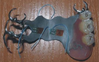
The article analyses the alar cast partial, which is presented in Fig. 1. It consists of a metal base – the saddle part and clasp elements. These elements located opposite acrylic teeth were omitted during scanning, because these are, by definition, immovable places, for which a precise inventory of geometry is not necessary.
The analysed denture was scanned with the use of a laser method, and then, it was modelled in the form of a thin coating oriented in a three-axis coordinate system. By scanning two sides of the denture, and then, applying them on top of one another, it was possible to mark the denture coating thickness. It was important to precisely define the central surface of the coating, which was tested in the further part of the paper. Owing to the developed programme, based on the data of two surfaces, one “central” surface described by a set of triangular elements of a given thickness at each point was finally obtained. This thickness was calculated while determining the central surface on the basis of distances between the determined surfaces. The obtained result of the denture thickness was presented in Fig. 2.
Fig. 1Experimental denture
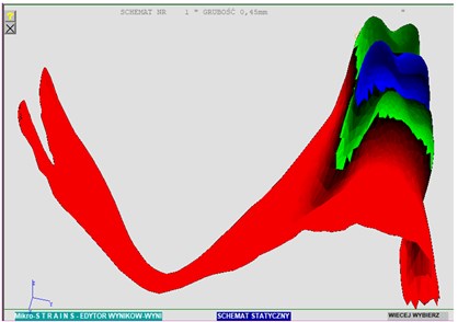
The plate which the denture is made of has a fixed thickness, and in Fig. 2, the varied thickness, resulting from the scanning inaccuracy, is clearly visible. Finally, a nominal plate thickness of 0.45 mm in the entire operating area of the denture was adopted. In addition, the denture model was turned at the appropriate angle, in order to possibly bring its arrangement closer to the natural one, occurring during operation. The result was shown in Fig. 3.
Fig. 2Thickness distribution – varied thickness
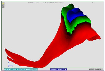
Fig. 3Thickness distribution and the denture arrangement used in calculations
3. Determination of boundary conditions
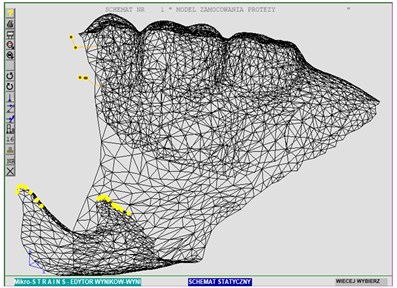
During the denture scanning, there is discretization aimed at changing the continuous medium into discrete one. Then, a model with a finite number of nodes was obtained. In the next stage, it was important to appropriately model the proper denture fastening corresponding to its actual fixation and mobility. The “bridge” denture fastening actually consisting of many bar elements, at the same time, resting on and covering teeth, was implemented as hinged immovable supports (marked with yellow). It means that angular displacements, that are rotations, are permissible, at the same time, making linear displacements impossible. The “clasp” denture fastening close to the saddle was implemented with the use of bar elements, corresponding to the parameters (lengths, sections, material) as in the actual denture, added to the model. The result was shown in Fig. 4.
Other nodes rest on the mucous membrane, and they obtain the status of unilateral elastic supports. The supports are defined in accordance with the global coordinate system, and the elastic supports are defined in such a manner [1, 2, 11, 12]. The applied model of the elastic support, as well as a detailed description of its implementation were described in the paper [6, 7].
Fig. 4Place and method of fastening the denture
4. Results of the computational experiment
On the presented model of the denture, a simulation with the use of the programme developed for the static analysis of MICRO-STRAINS surface structures was carried out. During the calculation, 3 nodes corresponding, in fact, to the central areas of teeth, were sequentially loaded. Nodes: 577, 2162, 2387 correspond to the following teeth: 5, 6, 7. A maximum load value of 19.62 N was determined in each node [9, 10]. Load places marked in green were presented in Fig. 5. When performing the calculations, a value of the base coefficient of 3.85 N/mm was adopted [6]. The article presents the example results of the analysis at the tooth load 7 Extreme resulting values of deflections were presented in the table. The graphical presentation shows:
• The arrangement of contact nodes with the base – elastic supports;
• The denture deformation under the impact of the applied load;
• The contour plan of the denture stress according to Huber’s strength hypothesis;
• Distribution of deflections in the direction.
Table 1Tooth load 7 – node 2387
Extreme displacement values [mm] | |||||||||
In the global direction | In the local direction Z | ||||||||
Maximum | Minimum | Maximum | Minimum | ||||||
Node | Value | Node | Value | Element | Node | Value | Element | Node | Value |
1159 | 0.00112 | 1958 | -0.537 | 3773 | 62 | –0.310 | 3792 | 1697 | 0.502 |
The basic FEM solution is a solution of the system of linear equations, as a result of which the displacement values in the analysed structure nodes are obtained. On the basis of the obtained displacements, it is possible to achieve the deformation values as derivatives of these displacements [1, 3].
Fig. 5Places of the introduction of loads
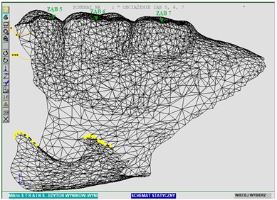
Fig. 6The arrangement of nodes in contact with the base
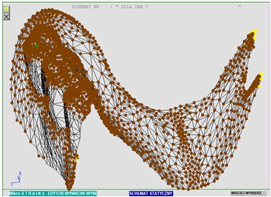
Fig. 7The denture deformation under the load – view 1
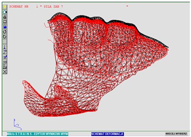
Fig. 8The denture deformation under the load – view 2
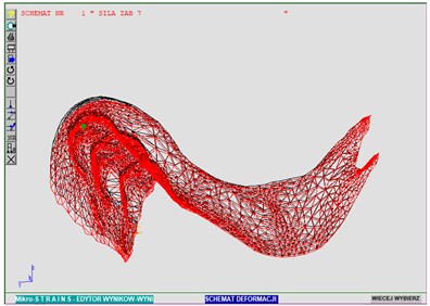
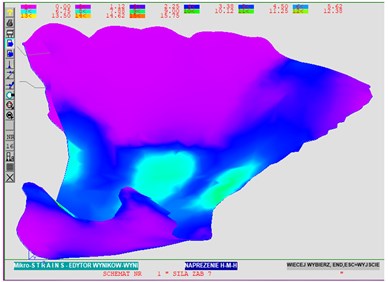
Fig. 9Distribution of destructive stress values in accordance with the H-M-H hypothesis
5. Conclusions
The strength analysis of the denture requires the consideration of its cooperation with the base in the form of soft tissues of the palate and gums. When performing the analysis without considering the elastic base, other displacement values were obtained [1, 2], [5-8].
The arrangement of nodes having contact with the base corresponds to the obtained deformation diagrams. In Fig. 8, on the left side, it is possible to observe a detachment zone, that is the places which lost the contact with the base under the load.
The diagram of the distribution of destructive stress values according to Huber – values in N/mm2 allow to compare the obtained stresses with the denture load capacity to tearing.
It is possible to form the plate of dentures based on the numerically developed virtual model. By making many rapid changes in the shape, dimensions or strength parameters, it is possible to obtain an optimal denture within the state of load capacity (stress), and the state of use (deflection) [13, 14].
Within the framework of the carried out analysis, it is possible to obtain detailed numerical values other than those shown in the paper, the resulting figures, e.g. of internal forces in the form of stresses and moments for any element of the denture, reactions in fixed supports and points of support on the mucous membrane, or other – in accordance with the possibilities of the editor of results of Micro-Strains System [6, 10].
References
-
Michalski W., Komorek Z., Michniowski Z., Kuchta M. Strength tests on the material of connections for experimental stress measurements and calculations on the numerical model of the upper partial denture. Prosthodontics, Vol. 3, 2006, p. 147-156.
-
Michalski W., Michniowski Z., Gryszkiewicz M., Kuchta M. Modelling and static analysis of the alar cast partial with separated kinematics with the use of the finite element method. Measurement, Automation and Monitoring, Vol. 5, 2006, p. 161-169.
-
Becker B., Nägerl H., Kubein Meesenburg D., Fanghänel J. Elastic properties of live human periodontal ligament, proceedings. 2nd World Congress of Biomechanics, Amsterdam, 1994.
-
Igarashi Y., Ogata A., Kuroiwa A., Wang C. H. Stress distribution and abutment tooth mobility of distal-extension removable partial dentures with different retainers: an in vivo study. Journal of Oral Rehabilitation, Vol. 26, Issue 2, 1999, p. 111-116.
-
Józefowicz W. Test results of elasticity modules of the prosthetic base soft tissues. Prosthodontics, Vol. 3, 1970, p. 15-21.
-
Kuchta M., Wnuk M. Modelling of the denture elastic support. Electrotechnical Review, Vol. 12, 2010, p. 79-82.
-
Kawasaki T., Takayama D., Yamada T., Notani K. Relationship between the stress distribution and the shape of the alveolar residual ridge - three dimensional behaviour of a lower complete denture. Journal of Oral Rehabilitation, Vol. 28, Issue 10, 2001, p. 221-228.
-
Korioth T. W. P., Waldron T. W., Versluis A., Schulte J. K. Forces and moments generated at the dental incisors during forceful biting in humans. Journal of Biomechanics, Vol. 30, Issue 6, 1997, p. 631-633.
-
Kuchta M., Kwiatos K., Fokow K. Measurement system for diagnostic tests of dentures. Diagnostics, Vol. 3, 2006, p. 187-193.
-
Michalski W., Kuchta M., Fokow K., Chwaleba A. Tensometric stress measurement of a large connection at the wing displacement of the upper partial denture in experimental conditions. Part II. Assessment of the distribution of deformations and linear displacements for numerical simulation. Prosthodontics, Vol. 5, 2005, p. 325-335.
-
Mori S., Sato T., Hara T., Nakashima K. Effect of continuous pressure on histopathological changes in denture supporting tissues. Journal of Oral Rehabilitation, Vol. 24, 1997, p. 37-46.
-
Oguz O., Kaan O., Secil A., Murat I., Burak B., Bayram U. S. The effect of removable partial dentures on alveolar bone resorption: a retrospective study with cone-beam computed tomography. Journal of Prosthodontics, Vol. 22, 2012, p. 42-48.
-
Raigrodski T., Ariel J. Contemporary materials and technologies for all-ceramic fixed partial dentures. Journal of Prosthetic Dentistry, Vol. 92, Issue 6, 2004, p. 557-562.
-
Sato Y., Abe Y., Okane H., Tsuga K. Finite element analysis of stress relaxation in soft denture liner. Journal of Oral Rehabilitation, Vol. 27, Issue 8, 2000, p. 345-352.
About this article

