Abstract
The purpose of this study is to show the influence of bending-torsion coupling on natural frequencies and mode shapes of aircraft wings by using two finite element beam formulations. The bending-torsion coupling parameters are the geometric parameter (distance between the mass axis and elastic axis of the cross-section of the beam) and the material coupling due to laminated composites. Cubic and high-order Hermite finite element interpolations are presented in this study, in order to show the influence of geometric and material coupling on natural frequencies and mode shapes. Starting by the governing partial differential equations of motion for the coupled bending-torsion beam with the bending and torsion equations, the Galerkin’s method is used with high-order finite element interpolation to obtain the high-order Hermitian shape functions. The mass and stiffness matrices are obtained using the kinetic energy and potential energy, respectively. The beam finite element has two nodes, the cubic element has three degrees of freedom at each end (transvers displacement, slope and torsion), where the high order element has five degrees of freedom at each end (transvers displacement, slope, curvature, gradient of curvature and torsion). The mass matrix contains geometric coupling terms and the stiffness matrix contains terms of material bending-torsion coupling. The obtained results using cubic and high-order finite element Euler-Bernoulli beam formulations are compared for a free vibration analysis of Goland metallic wing (geometric coupling) and validated with Dynamic Stiffness Method for composite wings.
1. Introduction
Many analytical and numerical methods (Finite Element Method, Dynamic Stiffness method DSM, etc.) are adopted to determine approximate natural frequencies and mode shapes of uniform beams [1]. A high-order finite element formulation is developed by Ganesan and Zabehollah [2] for vibration analysis of tapered composite beams. Vibrations measurements of a wing are investigated experimentally by using the method of time averaged projection moiré analyzed by Maskeliūnas et al. [3]. Omarov et al. [4] made a dynamic model to determinate the reduced mass and stiffness of flexural vibrating cantilever beams. The measurement of plane vibrations of a two elastic structure are analyzed by Maskeliūnas et al. [5].
A dynamic stiffness element for free vibration analysis of composite beams and its application to aircraft wings is developed by Banerjee et al. [1], where a dynamic stiffness matrix of a composite beam is used to investigate it’s free vibration characteristics. A finite element parametric modeling technique of aircraft wing structures is given by Tang and Xi. [6]. The composite beam models are used to study the dynamic response and aeroelasticity for high-aspect-ratio of composite wings [7-10].
A variable-order finite-element method with application to the free-vibration of rotating beams is described by Hodge et Rutkowski [11], the elasto-dynamic response of a surface stiffened transversely isotropic half-space subjected to an internal time-harmonic normal load is studied in axisymmetric time-harmonic response of a surface-stiffened transversely isotropic half-space by Eskandari et al. [12]. An axisymmetric response of a bi-material full-space reinforced by an interfacial thin film presented by Ahmadi et al. [13] where Effects of thin film stiffness, material properties, loading depth, and surface/interface effect are studied.
A Kirchhoff thin plate perfectly bonded to the half-space is used to model the surface coating to study the Green’s functions of a surface-stiffened transversely isotropic half-space, Eskandari and Ahmadi [14].
A new novel collaborative optimization (MGACACO) algorithm based on the GA, ACO, the chaotic optimization method, multi-population strategy, adaptive control parameters and collaborative strategy is proposed to solve the complex optimization problems by Deng et al. [15, 16]. A PSO algorithm is used to optimize the parameters of least squares support vector machines (LS-SVM) [17] and solve multi-objective gate assignment [18]. A novel two-stage hybrid swarm intelligence optimization algorithm [19]. Other algorithms are used to solve optimization problems with application: a novel parallel hybrid intelligence optimization algorithm [20], A new feature extraction method based on EEMD and multi-scale fuzzy entropy for motor bearing [21], a novel collaborative optimization algorithm in solving complex optimization problems [22], and an improved self-adaptive differential evolution algorithm and its application [23]. A novel vibration suppression method based on fractional order Proportional-Integral-Derivative (PID) controller is proposed by Zhao et al. [24] in research on vibration suppression method of alternating current motor based on fractional order control strategy.
This paper presents the effect of both geometric and material coupling in free vibration analysis of coupled bending-torsional beams by using a high-order finite element formulation. The bending-torsion coupling coefficient considered here is given without definition of the fiber orientation of laminate beams and the results are validated with those given by the Dynamic Stiffness Method DSM for Euler-Bernoulli beam model [1].
2. Finite element modeling
The cubic and high-order finite element interpolations are adopted to model the wing structure and deduce its global mass and global stiffness matrices. The kinetic and potential energies are used to obtain the mass matrix and the stiffness matrix of the beam element [1]. The mass matrix contains geometric coupling terms due to (distance between the mass and elastic axis) and the stiffness matrix contains the terms of rigidity bending-torsion coupling (laminated beam or multilayered beams).
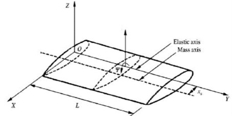
Fig. 1Coupled Euler-Bernoulli beam
2.1. The bending-torsion coupled beam element
The governing partial differential equations of motion for the coupled bending-torsion free natural vibration of the composite beam are given by [1, 25, 26]:
where is the transverse displacement of the beam, is the bending stiffness, is the torsion stiffness and the rigidity of bending-torsion coupling, m, is the mass per unit in length and the moment of inertia about the axis elastic, is the geometric coupling.
2.2. The Euler-Bernoulli beam model
The Euler-Bernoulli equation of beam bending (without externally pressure loading) is [27]:
where is mass density per volume.
2.2.1. Cubic finite element Hermitian beam
The cubic finite element Hermitian beam developed and described by Kown and Bang [27, 31], the cubic element has two nodes at the ends and at each end two degrees of freedom, the transverse displacement and the slope [28, 31]:
The evaluation of the transverse displacement and slope at both nodes gives the followed system: ; ; ; ; is the length of the beam element:
Solving the system Eq. (5) to obtain the coefficients and the transverse displacement assumption gives:
where the Hermitian shape functions of the beam (see Appendix).
2.2.2. High-order finite element beam
The weighted residual, Galerkin’s method is presented, to the beam Eq. (2) to develop the high-order finite element interpolation of the beam and the corresponding matrix equations.
The high-order finite element beam element presented in this study, has two nodes at the ends and at each end node four degrees of freedom [2], where is the transverse displacement, is the slope, is the curvature and is the gradient of curvature.
The assumption of deflection function is given using high order finite element polynomial function for, the degrees of this polynomial function is seven (eight nodal variables for the beam element):
From the Eq. (8), we can obtained the nodal variables for each node where:
– The slope is computed as:
– The curvature is:
– The gradient of curvature is:
The evaluation of these nodal variables on each node of the beam element gives:
where ; are the shape functions of the high order beam finite element (see Appendix).
2.2.3. The torsion in the beam
A linear shape functions are given for the torsion of the beam [31]. The beam element has two nodes as described in previous sections each node has one degrees of freedom and . The linear function is:
The introducing of boundary conditions in the element , gives:
where are the linear shape functions of the beamin torsion (see Appendix).
2.3. Modal analysis
The free vibration analysis (modal analysis) plays an important role in aircraft design. The energy method is used to determinate the global mass and stiffness matrices of the beam. The natural frequencies and mode shapes are obtained by solving the eigenvalue matrix equation of the wing structure.
2.3.1. Kinetic energy
The kinetic energy of bending-torsion coupled beam is [1]:
The kinetic energy can be written as [28, 29]:
where is the mass matrix of bending-torsion coupled beam [27, 31]:
2.3.2. Potential energy
The potential energy of bending-torsion coupled composite beam is [1]:
The potential energy can be written as [28, 29]:
where is the stiffness matrix of bending-torsion coupled beam [1]:
where the stiffness matrix of bending, is the coupled stiffness matrix and is the stiffness matrix of torsion.
2.3.3. Natural frequencies and mode shapes
The matrix system obtained by the discrete equations of motion for wing structure is [1, 3, 11]:
where and are the global mass and stiffness matrices, respectively.
3. Results and discussions
The free vibration analysis of composite wing is investigated using a cubic and high-order finite element Euler-Bernoulli beam formulations in order to show the effect of geometric coupling shown in Fig. 1 on vibration frequencies and mode shapes for metallic wings and generalized to composite wings where the anisotropy of materials has significant effects on natural frequencies and mode shapes.
3.1. Isotropic beam model (Goland wing)
The Goland’s wing properties are given in Table 1 [1, 7, 30], in order to validate the results obtained by the present work with the Dynamic Stiffness Method results, for a free vibration analysis of metallic wings.
The three first frequencies (rad/s) obtained by the cubic and high-order finite element beam model are compared with the DSM results Banerjee et al. [1] where the geometric coupling represented by rang of values of are given in Table 2.
Table 1Goland wing properties
(Nm2) | GJ K (Nm2) | (kg/m) | (kg·m) | (m) |
9.75 106 | 9.88 105 | 35.75 | 8.65 | 6 |
Table 2The three first frequencies of Goland wing
(m) | [rad/s] | [rad/s] | [rad/s] | ||||||
DSM results [1] | Cubic FEM | High-order FEM | DSM results [1] | Cubic FEM | High-order FEM | DSM results [1] | Cubic FEM | High-order FEM | |
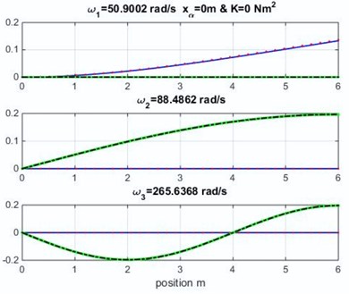
0 | 51.005 | 51.005 | 50.900 | 88.478 | 88.479 | 88.486 | 265.44 | 265.46 | 265.636 |
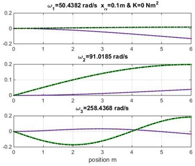
0.1 | 50.539 | 50.539 | 50.438 | 91.02 | 91.02 | 91.018 | 258.43 | 258.44 | 258.436 |
0.2 | 49.331 | 49.331 | 49.238 | 99.202 | 99.203 | 99.189 | 246.60 | 246.612 | 246.526 |
0.3 | 47.741 | 47.741 | 47.658 | 115.74 | 115.738 | 115.706 | 238.10 | 238.114 | 237.994 |
The mode shapes obtained for the uncoupled case and is shown in Fig. 2 (the geometric and material coupling are equal to zero, and this case is similar to Euler-Bernoulli classical beam theory). The obtained results in Fig. 2 show the effect of the geometric coupling on mode shapes and natural frequencies of Goland wing.
It appears clearly that the natural frequencies in Table 2 and the mode shapes in Fig. 2 for the cubic formulation and high-order formulation are very similar to those obtained by Banerjee et al. [1] for metallic wing using DSM approximation method varying the geometric coupling which affect the naturel frequencies.
Fig. 2Mode shapes for various geometric coupling xα of the wing
3.2. Composite wing results
Various values of material coupling are considered to illustrate the effect of bending-torsion coupling due to material anisotropy in mode shapes and natural frequencies.
The material coupling rigidities given in this section are proposed by Banerjee et al. [1]. These rigidities can be obtained by laminated composites.
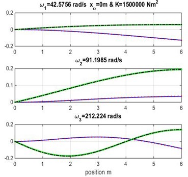
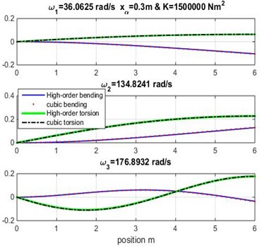
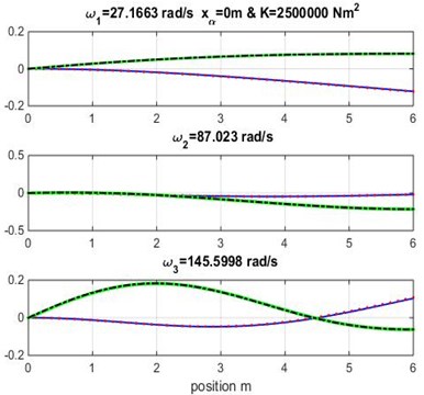
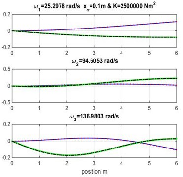
The mode shapes for range of values of geometric coupling and various material coupling are shown in Figs. 3, 4 and 5. Observe that the obtained mode curves are different, in which the bending and torsion coupled modes is remarkable in each material coupling value.
Fig. 3Mode shapes for rigidity coupling K= 1.5×10⁶ and various geometric coupling xα of cantilever wing
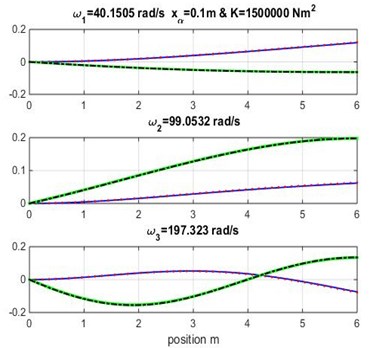
The three first natural frequencies obtained from modal analysis of composite beam using cubic and high-order finite element beam are presented in Tables 3, 4 and 5 varying both geometric and material coupling for the beam, these obtained results are compared to those obtained by Banerjee et al. [1] using Dynamic Stiffness Method.
Table 3First frequency results of composite wing
(m) | (Nm2)×106 | [rad/s] | ||
DSM results [1] | Hermite FEM beam model | High-order FEM Beam model | ||
0.1 | 1.5 | 40.25 | 40.25 | 40.15 |
2 | 33.96 | 33.96 | 33.84 | |
2.5 | 25.44 | 25.44 | 25.29 | |
0.2 | 1.5 | 38.07 | 38.07 | 37.97 |
2 | 31.98 | 31.98 | 31.87 | |
2.5 | 23.88 | 23.88 | 23.75 | |
0.3 | 1.5 | 36.14 | 36.14 | 36.06 |
2 | 30.28 | 30.28 | 30.18 | |
2.5 | 22.57 | 22.57 | 22.44 | |
Table 4Second frequency results of composite wing
(m) | (Nm2)×106 | [rad/s] | ||
DSM results [1] | Hermite FEM beam model | High-order FEM Beam model | ||
0.1 | 1.5 | 99.072 | 99.072 | 99.05 |
2 | 100.47 | 100.46 | 100.42 | |
2.5 | 94.82 | 94.81 | 94.60 | |
0.2 | 1.5 | 112.22 | 112.22 | 112.19 |
2 | 114.71 | 114.70 | 114.65 | |
2.5 | 104.36 | 104.36 | 104.00 | |
0.3 | 1.5 | 134.86 | 134.86 | 134.62 |
2 | 139.97 | 139.96 | 139.89 | |
2.5 | 109.62 | 109.63 | 109.10 | |
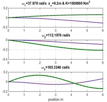
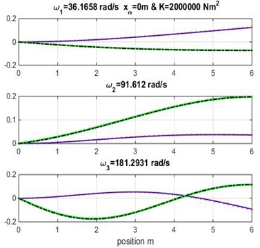
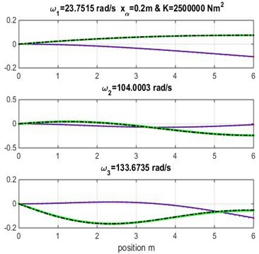
Fig. 4Mode shapes for rigidity coupling K= 2×10⁶ and various geometric coupling xα of cantilever wing
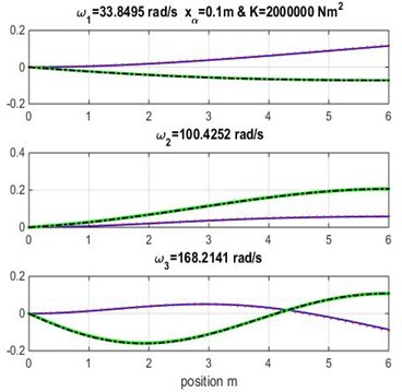
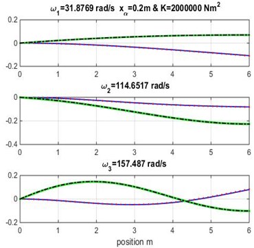
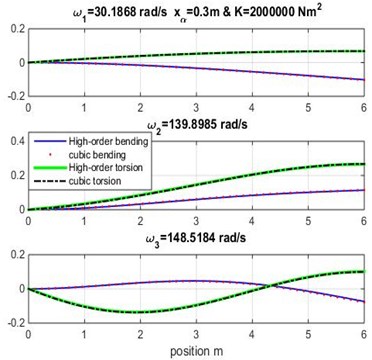
It appears clearly from Tables 3, 4 and 5 that the three first naturel frequencies , and are almost similar for the Dynamic Stiffness Method [1] with the cubic and high-order finite element formulations varying both geometric coupling and material coupling.
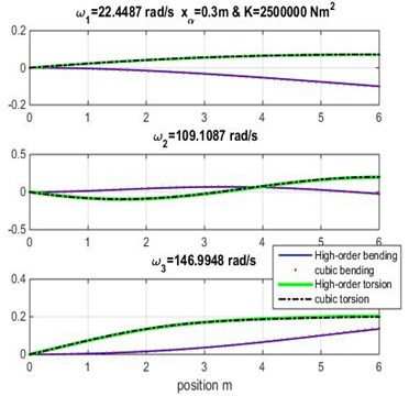
Figs. 3, 4 and 5 show the bending and torsion mode shapes of the three first natural frequencies of cubic and high-order formulations for the coupled bending-torsional composite wing. The coupled case 0.2 m and 2.0×10⁶ N.m2 curves are almost similar to those given by Banerjee et al. [1].
Table 5Third frequency results of composite wing
(m) | (Nm2)×106 | [rad/s] | ||
DSM results [1] | Hermite FEM beam model | High-order FEM Beam model | ||
0.1 | 1.5 | 197.57 | 197.58 | 197.32 |
2 | 168.55 | 168.56 | 168.21 | |
2.5 | 137.34 | 137.34 | 136.98 | |
0.2 | 1.5 | 185.57 | 185.58 | 185.32 |
2 | 157.81 | 157.81 | 157.48 | |
2.5 | 133.87 | 133.87 | 133.67 | |
0.3 | 1.5 | 177.15 | 177.16 | 176.89 |
2 | 148.83 | 148.83 | 148.51 | |
2.5 | 147.03 | 147.03 | 146.99 | |
Fig. 5Mode shapes for rigidity coupling K= 2.5×10⁶ and various geometric coupling xα of the wing
4. Conclusions
The free vibration analysis by measurement of natural frequencies and mode shapes of composite wings using cubic and high-order finite element coupled bending-torsion beam is presented and validated in this study. A high-order finite element Euler-Bernoulli beam model has been developed for isotropic materials, in first time, and generalized to laminated composite beams.
The results obtained by modal analysis (natural frequencies and mode shapes) are validated with dynamic stiffness approximation method (DSM). The geometric coupling and material coupling have a very important role in dynamic and aeroelasticity (fluid/structure interaction) problems. The varying of these parameters for Goland metallic wing can be generalized for all metallic and composite wings, in which the choice of aerodynamic or structural design of wing (or tailplane) depends on them (both geometric and material coupling). The results obtained from this study can be used for aeroelasticity studies, dynamic and frequency, response for random excitations obtained from gusting forces and it’s can be generalized to all Aircraft structure.
References
-
Banerjee J. R., Su H., Jayatunga C. A dynamic stiffness element for free Vibration analysis of composite beams and its application to aircraft wings. Computers and Structures, Vol. 86, 2008, p. 573-579.
-
Ganesan R., Zabehollah A. Vibration analysis of tapered composite beams using a high-order finite element. Part 1: Formulation, Vol. 77, 2007, p. 306-318.
-
Maskeliūnas V., Maskeliūnas R., Paškevičius P., Ragulskis L. Measurement of Vibrations of Wings. Journal of Measurements in Engineering, Vol. 4, Issue 3, 2016, p. 183-187.
-
Tamerlan Omarov, Kuralay Tulegenova, Yerulan Bekenov, Gulnara Abdraimova, Algazy Zhauyt, Muslimzhan Ibadullayev Determination of reduced mass and stiffness of flexural vibrating cantilever beam. Journal of Measurements in Engineering, Vol. 6, Issue 1, 2018, p. 1-9.
-
Maskeliūnas R., Ragulskis K., Paškevičius P., Patašienė L., Pauliukas A., Ragulskis L. Measurement of plane vibrations of a two dimensional elastic structure. Journal of Measurements in Engineering, Vol. 3, Issue 2, 2015, p. 42-47.
-
Tang J., Xi P. A finite element parametric modeling technique of aircraft wing structures. Chinese Journal of Aeronautics, Vol. 26, Issue 5, 2013, p. 1202-1210.
-
Cesnik Carlos E. S., Hodgesy Dewey H., Mayuresh Patil J. Aeroelastic analysis of composite wings. Structural Dynamics and Materials Conference, Salt Lake City, Utah, 1996.
-
Mayuresh Patil J., Hodges Dewey H., Cesnik Carlos E. S. Nonlinear aeroelastic analysis of aircraft with high-aspect-ratio wings. 39th AIAA/ASME/ASCE/AHS/ASC Structures, Structural Dynamics, and Materials Conference and Exhibit, Structures, Structural Dynamics, and Materials and Co-located Conferences, 1998.
-
Zhao Y. H., Hu H. Y. Structural modeling and aeroelastic analysis of high-aspect-ratio composite wings. Chinese Journal of Aeronautics, Vol. 18, Issue 1, 2005, p. 25-30.
-
Haddadpour H., Kouchakzadeh M. A., Shadmehri F. Aeroelastic instability of aircraft composite wings in incompressible flow. Composite Structures, Vol. 83, 2008, p. 93-99.
-
Hodges D. Y., Rutkowski M. Y. Free-vibration analysis of rotating beams by a variable-order finite-element method. AIAA Journal, Vol. 19, Issue 11, 1981, p. 1459-1466.
-
Eskandari M., Samea P., Ahmadi S. F. Axisymmetric time-harmonic response of a surface-stiffened transversely isotropic half-space. Meccanica, Vol. 52, Issues 1-2, 2017, p. 183-196.
-
Ahmadi S. F., Samea P., Eskandari M. Axisymmetric response of a bi-material full-space reinforced by an interfacial thin film. International Journal of Solids and Structures, 90, p. 251-260.
-
Eskandari M., Ahmadi S. F. Green’s functions of a surface-stiffened transversely isotropic half-space. International Journal of Solids and Structures, Vol. 49, Issues 23-24, 2012, p. 3282-3290.
-
Deng Wu, Zhang Shengjie, Zhao Huimin, Yang Xinhua A novel fault diagnosis method based on integrating empirical wavelet transform and fuzzy entropy for motor bearing. IEEE Access, Vol. 6, 2018, p. 35042-35056.
-
Deng Wu, Zhao Huimin, Liu Jingjing, Yan Xiaolin, Li Yuanyuan, Yin Lifeng, Ding Chuanhua An improved CACO algorithm based on adaptive method and multi-variant strategies. Soft Computing, Vol. 19, Issue 3, 2015, p. 701-713.
-
Deng Wu, Yao Rui, Zhao Huimin, Yang Xinhua, Li Guangyu A novel intelligent diagnosis method using optimal LS-SVM with improved PSO algorithm. Soft Computing, 2017, https://doi.org/10.1007/s00500-017-2940-9.
-
Deng Wu, Zhao Huimin, Yang Xinhua, Xiong Juxia, Li Bo Study on an improved adaptive PSO algorithm for solving multi-objective gate assignment. Applied Soft Computing, Vol. 59, 2017, p. 288-302.
-
Deng Wu, Chen Rong, He Bing, Liu Yaqing, Yin Lifeng, Guo Jinghuan A novel two-stage hybrid swarm intelligence optimization algorithm and application. Soft Computing, Vol. 16, Issue 10, 2012, p. 1707-1722.
-
Deng Wu, Chen Rong, Gao Jian, Song Yingjie, Xu Junjie A novel parallel hybrid intelligence optimization algorithm for function approximation problem. Computers and Mathematics with Applications, Vol. 63, Issue 1, 2012, p. 325-336.
-
Zhao Huimin, Sun Meng, Deng Wu, Yang Xinhua A new feature extraction method based on EEMD and multi-scale fuzzy entropy for motor bearing. Entropy, Vol. 19, Issue 1, 2017, p. 14.
-
Deng Wu, Zhao Huimin, Zou Li, Li Guangyu, Yang Xinhua, Wu Daqing A novel collaborative optimization algorithm in solving complex optimization problems. Soft Computing, Vol. 21, Issue 15, 2017, p. 4387-4398.
-
Deng Wu, Yang Xinhua, Zou Li, Wang Meng, Liu Yaqing, Li Yuanyuan An improved self-adaptive differential evolution algorithm and its application. Chemometrics and Intelligent Laboratory Systems, Vol. 128, 2013, p. 66-76.
-
Zhao H. M., Li D. Y., Deng W., Yang X. H. Research on vibration suppression method of alternating current motor based on fractional order control strategy. Proceedings of the Institution of Mechanical Engineers Part E-Journal of Process Mechanical Engineering, Vol. 231, Issue 3, 2017, p. 786-799.
-
Banerjee J. R. Explicite analytical expressions for frequency equation and mode shapes of composite beams. International Journal of Solids and Structures, Vol. 38, 2001, p. 2415-2426.
-
Guo S. Aeroelastic optimisation of an aerobatic aircraft wing structure. Aerospace Science and Technology, Vol. 11, 2007, p. 396-404.
-
Kwon W. Y., Bang H. The Finite Element Method using MATLAB. CRC Press, New York, 1997.
-
Tanka M., Bercin A. N. Finite element bending of a coupled bending and torsional free vibration of uniform beams with an arbitrary cross-section. Journal of Applied Mathematics and Modeling, Vol. 21, 1997, p. 339-344.
-
Oz H. R. Calculation of the natural frequencies of a beam mass system using finite element method. Journal of Mathematical and Computational Applications, Vol. 2, 2000, p. 67-75.
-
Kirsch Bertrand, Montagnier Olivier, Bénard Emmanuel, Faur Thierry M. Dynamic aeroelastic simulation of composite wing for HALE UAV application. 7th European Conference for Aeronautics and Aerospace Sciences (EUCASS), 2017.
-
Wright Jan R., Cooper E. Introduction to Aircraft Aeroelasticity and Loads. John Wiley and Sons, Chichester, 2007.
Cited by
About this article

