Abstract
This study developed to solve the problem of prediction of the natural frequencies of free vibration for laminated beams. The study presented the natural frequencies of composite beams with four layered and different boundary conditions. In each boundary condition, two cases are assumed: movable ends and immovable ends. Numerical results are obtained for the same material to demonstrate the effects of the aspect ratio, fiber orientation, and the beam end-movements on the non-dimensional natural frequencies of beams. Two aspect ratios are given in the numerical results, one is for relatively short-thick beams, while the other is for slender beams. It was found that the results of the non-dimensional frequencies obtained from the short-thick beams are generally much less than those obtained from the other slender beams for same fiber orientation and generally, the frequencies of longitudinal vibration increase as the aspect ratio increased. It was also found the values of the non-dimensional frequencies of the transverse modes are not affected by the longitudinal movements of the ends since these modes are generated by lateral movements only. However, the values of the natural frequencies of longitudinal modes are found to be the same for all beams with movable ends since they are generated by longitudinal movements only.
Highlights
- The study presented the natural frequencies of composite laminated beams.
- First order shear deformation (FSDT) theory is used, and finite element method is employed.
- The aspect or slenderness ratio has a considerable effect on all modes of vibration.
- The natural frequencies of a laminated beam generally increase with the aspect ratio.
- All beams with movable ends have equal longitudinal frequencies of vibration, while those of beams with immovable ends are different.
1. Introduction
Composite have been used in engineering structures over the last four decades or so. They could be seen in a variety of applications as in craft wings and fuselage, satellites helicopter blades, wind turbines boats and vessels, tubes and tanks etc. Their advantages over traditional materials are widely recognized and these are high strength to weight ratio, and their properties which can tailored according to need. Other advantages include high stiffness, high fatigue and corrosion resistance, good friction characteristics, and ease of fabrication. They are made of fiber such as glass, carbon, boron, etc. embedded in matrix or suitable resin that act as binding material. The increasing use of composites has been required a good understanding of composite mechanics and their behavior. Many mathematical models for laminates subjected to static and dynamic loading have been developed. This paper addresses free vibration. The knowledge of the few lower natural frequencies of a structure is utmost importance in order to save it in service from being subjected to unnecessary large amplitude of motion which can cause immediate collapse or ultimate failure by fatigue.
Free vibration analysis of laminated composite beams is presented by P. Subramanian, R. A. Jafari-Talookolaei et al. and A. Pagani [1-3] reference [1] used two higher order displacement based shear deformation theories, while references and [2, 3] used the first order shear deformation theory. M. Rueppel et al. [4] studied the damping of carbon fibre and flax fibre angle-ply composite laminate. Torabi K. et al. [5] Investigated on the effects of delamination size and its thickness-wise and lengthwise location on the vibration characteristics of cross-ply laminated composite beams. Analytical solutions for free vibration and buckling of composite beams using a higher order beam theory presented by He G. et al. [6]. Vibration prediction of thin-walled composite I-beams using scaled models analyzed by M. E. Asl et al. [7]. Within that study, which is an extension of Authors’ previous work on design of scaled composite models [8-10], similitude theory is applied to the governing equations of motion for vibration of a thin walled composite I-beam. Algarray et al. [11] studied the effects of end conditions of Cross-Ply laminated composite beams on their dimensionless natural frequencies
2. Modeling analysis
Fig. 1. Showed a composite laminated beam made up of layers with different orientation, thickness, and properties. Where is the length, b is breadth and is depth.
Fig. 1Composite laminated beam
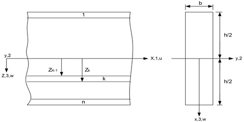
Treat the beam as a plane stress problem and employ first-order shear deformation theory. The longitudinal displacement () and the lateral displacement () can be written as follows:
where and are the mid-plane longitudinal and lateral displacements, is the rotation of the deformed section about the -axis, is the perpendicular distance from mid-plane to the layer plane, and is time.
The Strain-Displacement Relations:
where: is the longitudinal strain, and is the through-thickness shear strain.
Fig. 2Composite laminated beam with 3-noded lineal element
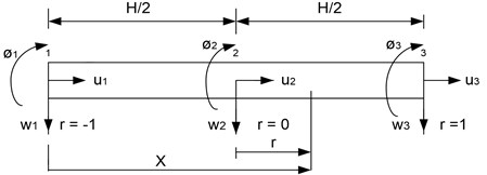
By employing 3-noded lineal element as shown in Fig. 2.
The displacements can be expressed in terms of shape function and nodal displacements:
The shape functions are: , , .
From Eqs. (2), (3), the strains can be written as:
where:
And is the vector of nodal displacements , 1, 2, 3.
The stress-strain relation:
where , and the matrix containing the transformed elastic constants:
Substitute Eq. (4) in Eq. (5):
The strain energy:
where:
The kinetic energy:
where is density and the dot denotes differentiation with time:
where:
In the above derivation it is assumed the motion is harmonic and is circular frequency.
In the absence of damping and external nodal load, the total energy is:
The principle of minimum energy requires that:
The condition yields the equation of motion:
where:
and is number of elements. To facilitate the solution of Eq. (10), we introduce the following quantities:
where is the shear correction factor.
The transformed elastic constants are:
In which:
And is the angle of orientation of the ply with respect to the beam axis:
Non-dimensional quantities used in the analysis are:
The element stiffness matrix:
The mass matrix is 9×9 symmetrical matrix:
3. Results and discussion
3.1. Effect of aspect ratios
Two aspect ratios are given in the numerical results, which are 10 and 50. The first one is for relatively short-thick beams, while the other is for slender beams. The results of the non-dimensional frequencies obtained from the aspect ratio 10 are generally much less than those obtained from the other aspect ratio 50 for same fiber orientation. For example, the fundamental mode of the non-dimensional natural frequencies for a symmetric [30/–30/–30/30] angle-ply hinged _hinged beam with immovable ends is 1.9918 for the aspect ratio 10, and 2.1947 for the aspect ratio 50 as can be seen in Table 1.
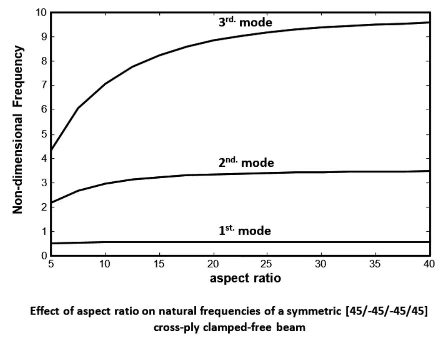
This observation can be seen in Fig. 3 to Fig. 5 for symmetric [45/–45/–45/45] angle-ply laminated beams. These figures show the variation of the non-dimensional frequencies with the aspect ratio range from 5 to 40 for the first three modes of vibration for all beams with immovable ends. It is obvious from the figure that the frequency increases rapidly for the range of aspect ratio from 5 to 20, and slows down beyond this range. When the aspect ratio is greater than 20, the beam is slender and consequently shear deformation and rotary inertia have small noticeable effects on the natural frequencies.
Table 2 shows the effect of aspect ratio in non-dimensional frequencies for symmetric [45/–45/–45/45] angle-ply beams. The percentage increase in the non-dimensional frequencies, for the first range of the aspect ratio, increases sharply as the mode order increased for all boundary conditions. For the second range, the percentage increase in frequencies is independent on the mode order. The longitudinal modes of free vibration are also affected by the change of aspect ratio. Generally, the frequencies of longitudinal vibration increase as the aspect ratio increased.
Table 1Non-dimensional natural frequencies ω¯=ωρL4/E1h2 [30/–30/–30/30] composite beams with different aspect ratio
Mode No. | Beam type aspect ratio ( 10) | |||||
CF | HH | CC | HC | HF | FF | |
1 | 0.7465 | 1.9918 | 3.4380 | 2.7113 | 3.0503 | 4.3728 |
2 | 3.7279 | 6.4128 | 7.4386 | 6.9645 | 7.9206 | 9.5329 |
3 | 8.4193 | 11.4744 | 12.0720 | 11.7816 | 12.1545* | 14.9573 |
4 | 12.1545* | 16.5865 | 16.9085 | 16.7518 | 13.1707 | 20.2046 |
5 | 13.4194 | 21.6353 | 21.8199 | 21.7278 | 18.3742 | 24.3090* |
6 | 18.5147 | 24.3090* | 24.3090* | 24.3090* | 23.4730 | 25.3532 |
7 | 23.5463 | 26.6166 | 26.7237 | 26.6709 | 28.4805 | 30.3492 |
8 | 28.5288 | 31.5448 | 31.6114 | 31.5778 | 33.4158 | 35.3042 |
9 | 33.4400 | 36.4344 | 36.4743 | 36.4548 | 36.4635* | 40.0877 |
10 | 36.4635* | 41.2968 | 41.3227 | 41.3093 | 38.2900 | 44.9060 |
11 | 38.3118 | 46.1413 | 46.1540 | 46.1482 | 43.0983 | 48.6181* |
12 | 43.1022 | 48.6181* | 48.6181* | 48.6181* | 47.7785 | 48.9418 |
Mode No. | Beam type aspect ratio ( 50) | |||||
CF | HH | CC | HC | HF | FF | |
1 | 0.7837 | 2.1947 | 4.8908 | 3.4027 | 3.4251 | 4.9666 |
2 | 4.8503 | 8.6633 | 13.1481 | 10.8187 | 10.9431 | 13.4813 |
3 | 13.3186 | 19.0823 | 24.9877 | 21.9844 | 22.3328 | 25.8305 |
4 | 25.4001 | 32.9800 | 39.8324 | 36.3924 | 37.1019 | 41.4535 |
5 | 40.6240 | 49.8113 | 57.1574 | 53.4997 | 54.6965 | 59.7934 |
6 | 58.4417 | 69.0255 | 76.4775 | 72.7861 | 60.7725* | 80.3045 |
7 | 60.7725* | 90.1153 | 97.3759 | 93.7899 | 74.5680 | 102.4978 |
8 | 78.3401 | 112.6436 | 119.5087 | 116.1227 | 96.2177 | 121.5450* |
9 | 99.8689 | 121.5450* | 121.5450* | 121.5450* | 119.2209 | 125.9612 |
10 | 122.6521 | 136.2519 | 142.5999 | 139.4697 | 143.2325 | 150.3635 |
11 | 146.3874 | 160.6577 | 166.4325 | 163.5836 | 167.9831 | 175.4481 |
12 | 170.8386 | 185.6456 | 190.8379 | 188.2740 | 182.3175* | 201.0230 |
(*) Modes with predominance of longitudinal vibration | ||||||
Table 2The effect of aspect ratio in non-dimensional frequencies for symmetric [45/–45/–45/45] angle-ply beams
Beam type | Approximate % increase in non-dimensional frequencies | |||||
Aspect ratios from 5 to 20 | Aspect ratios from 20 to 40 | |||||
1st. mode | 2nd. mode | 3rd. mode | 1st. mode | 2st. mode | 3rd. mode | |
CF | 25 | 50 | 100 | 10 | 6 | 9 |
HH | 25 | 62 | 100 | 10 | 6 | 9 |
CC | 68 | 120 | 150 | 10 | 10 | 15 |
HC | 45 | 85 | 125 | 10 | 9 | 14 |
HF | 22 | 70 | 220 | 8 | 6 | 10 |
FF | 85 | 115 | 145 | 12 | 8 | 12 |
3.2. Effect of axial movements of the ends
From the results of Table 1, that the values of the non-dimensional frequencies of the transverse modes are not affected by the longitudinal movements of the ends since these modes are generated by lateral movements only (at the yellow shaded). However, the values of the natural frequencies of longitudinal modes are found to be the same for all beams with movable ends since they are generated by longitudinal movements only. Table 3 shows this observation for symmetric [60/–60/–60/60] laminated beams with aspect ratio of 10.
Fig. 3Effect of aspect ratio on natural frequencies of a symmetric [45/–45/–45/45] cross-play clamped-free beam
![Effect of aspect ratio on natural frequencies of a symmetric [45/–45/–45/45] cross-play clamped-free beam](https://static-01.extrica.com/articles/19355/19355-img3.jpg)
Fig. 4Effect of aspect ratio on natural frequencies of a symmetric [45/–45/–45/45] cross-play clamped-clamped beam
![Effect of aspect ratio on natural frequencies of a symmetric [45/–45/–45/45] cross-play clamped-clamped beam](https://static-01.extrica.com/articles/19355/19355-img4.jpg)
Fig. 5Effect of aspect ratio on natural frequencies of a symmetric [45/–45/–45/45] cross-play free-free beam
![Effect of aspect ratio on natural frequencies of a symmetric [45/–45/–45/45] cross-play free-free beam](https://static-01.extrica.com/articles/19355/19355-img5.jpg)
Table 1 also shows the fundamental modes of longitudinal vibration for various beams with immovable ends for the symmetric case [30/–30/–30/30] and for two aspect ratios, 10, and 50. It could be noticed that the values of non-dimensional natural frequencies of the longitudinal vibration for the clamped-free and hinged-free beams are equal, and those of the other beams are also the same. This phenomenon occurs since both clamped-free and hinged-free beams with immovable ends are the same when restricted from executing longitudinal motion at the ends. Similarly, the rest of beams with immovable ends have the same longitudinal end conditions.
Table 3The first two non-dimensional modes of longitudinal free vibration of [60/–60/–60/60] laminated beams with aspect ratio 10
Beam ends | Mode No. | Beam type | |||||
CF | HH | CC | HC | HF | FF | ||
Immovable | 1 | 5.6426 | 11.2852 | 11.2852 | 11.2852 | 5.6426 | 11.2852 |
2 | 16.9279 | 22.5705 | 22.5705 | 22.5705 | 16.9279 | 22.5705 | |
Movable | 1 | 11.2852 | 11.2852 | 11.2852 | 11.2852 | 11.2852 | 11.2852 |
2 | 22.5705 | 22.5705 | 22.5705 | 22.5705 | 22.5705 | 22.5705 | |
3.3. Verification
The natural frequencies results which obtained by this study are closer with Abramovich [12] results, as show in Table 4, and difference between two results less than 0.6 % for cantilever and clamp-clamp beams.
A third-order shear deformation theory was used by Kant et al. [13] in the analysis of the free vibration of composite and sandwich simply supported beams. Two comparisons of non-dimensional natural frequencies between the present method (using FSDT) and the results of this reference are presented in Table 5, which presented a comparison for symmetric [0/90/90/0] cross-ply laminated beams respectively, with aspect ratio of ( 5), where the shear effect is significant. The comparison shows a difference of less than 3.3 % associated with the fundamental frequency and less than 4.5 % for higher modes. These differences are due to the employment of different shear theories as stated bellow.
Table 4Non-dimensional frequencies of [0/90/90/0] composite beams with immovable ends and aspect ratio 10
Mode No. | Cantilever | Clamp- clamp | ||
Present | Ref. [11] | Present | Ref. [11] | |
1 | 0.8866 | 0.8819 | 3.6855 | 3.7576 |
2 | 4.1062 | 4.0259 | 7.7244 | 7.8718 |
3 | 8.9536 | 9.1085 | 12.381 | 12.573 |
4 | 11.504 | 12.193 | 17.192 | 17.373 |
5 | 13.924 | 14.080 | 22.119 | 22.200 |
6 | 18.980 | 18.980 | 23.007* | 23.007 |
Table 5Non-dimensional frequencies of [0/90/90/0] composite beams with simple support ends and aspect ratio 5
Mode No. | Present | Ref. [13] |
1 | 1.7619 | 1.820 |
2 | 4.2749 | 4.528 |
3 | 6.7214 | 7.201 |
4 | 9.1414 | 9.814 |
5 | 11.5783* | – |
(*) Mode with predominance of longitudinal vibration | ||
It is clear, from the above comparisons, that the differences are very small even for higher modes. This confirms the accuracy of the method of analysis and the computer program.
4. Conclusions
In this paper, free vibration of four layered composite beams has been studied. Both secondary effects of transverse shear deformation and rotary inertia were included in the analysis. A first-order shear deformation theory was applied in the analysis. A finite element model has been formulated to predict the non-dimensional natural frequencies and to study the influence of aspect ratio and movable ends of fibers on the natural frequencies. Different end conditions were studied which are clamped-free, hinged-hinged, clamped-clamped, hinged-clamped, hinged-free, and free-free beams with immovable and movable ends. The main conclusion is the natural frequencies of a laminated beam generally increase with the aspect ratio and all beams with movable ends have equal longitudinal frequencies of vibration, while those of beams with immovable ends are different. Namely, clamped-free and hinged-free beams with immovable ends have equal longitudinal frequencies, and the other beams have also equal longitudinal frequencies.
References
-
Subramanian P. Dynamic analysis of laminated composite beams using higher order theories and finite elements. Composite Structures, Vol. 73, Issue 3, 2006, p. 342-353.
-
Jafari Talookolaei R.-A., Abedi M., Attar M. In-plane and out-of-plane vibration modes of laminated composite beams with arbitrary lay-ups. Aerospace Science and Technology, Vol. 66, 2017, p. 366-379.
-
Pagani A., Carrera E., Boscolo M., Banerjee J. Refined dynamic stiffness elements applied to free vibration analysis of generally laminated composite beams with arbitrary boundary conditions. Composite Structures, Vol. 110, 2014, p. 305-316.
-
Rueppel M., Rion J., Dransfeld C., Fischer C., Masania K. Damping of carbon fibre and flax fibre angle-ply composite laminates. Composites Science and Technology, Vol. 146, 2017, p. 1-9.
-
Torabi K., Shariati Nia M., Heidari Rarani M. Experimental and theoretical investigation on transverse vibration of delaminated cross-ply composite beams. International Journal of Mechanical Sciences, Vols. 115-116, 2016, p. 1-11.
-
He G., Wang D., Yang X. Analytical solutions for free vibration and buckling of composite beams using a higher order beam theory. Acta Mechanica Solida Sinica, Vol. 29, Issue 3, 2016, p. 300-315.
-
Asl M. E., Niezrecki C., Sherwood J., Avitabile P. Vibration prediction of thin-walled composite I-beams using scaled models. Thin-Walled Structures, Vol. 113, 2017, p. 151-161.
-
Asl M. E., Niezrecki C., Sherwood J., Avitabile P. Similitude analysis of composite I-beams with application to subcomponent testing of wind turbine blades. Experimental and Applied Mechanics, Vol. 4, 2016, p. 115-126.
-
Asl M. E., Niezrecki C., Sherwood J., Avitabile P. Predicting the vibration response in subcomponent testing of wind turbine blades. Special Topics in Structural Dynamics, Vol. 6, 2015, p. 115-123.
-
Vo T. P., Lee J. Flexural-torsional coupled vibration and buckling of thin-walled open section composite beams using shear-deformable beam theory. International Journal of Mechanical Sciences, Vol. 51, Issue 9, 2009, p. 631-641.
-
Algarray A. F. A., Jun H., Mahdi I. E. M. Effects of end conditions of cross-ply laminated composite beams on their dimensionless natural frequencies. Journal of Applied Mechanics and Technical Physics, Vol. 58, Issue 6, 2017, p. 1108-1114.
-
Abramovich H., Livshits A. Free vibrations of non-symmetric cross-ply laminated composite beams. Journal of Sound and Vibration, Vol. 176, Issue 5, 1994, p. 597-612.
-
Marur S. R., Kant T. Transient dynamics of laminated beams: an evaluation with a higher-order refined theory. Composite Structures, Vol. 41, Issue 1, 1998, p. 1-11.
About this article

